

Page 1

Chevrolet/GMC Class T6500/7500/8500
i
Low Cab Forward
MODEL SYMBOL CHART ...................................................................................................................................................................................1
CHASSIS
& Isuzu Class FTR/FTV/FTX
PAGE
General Arrangement – T6/T7/T8 F042 ....................................................................................................................................................
General Arrangement – T8F064 .................................................................................................................................................................
Body Payload Weight Distribution – T6/T7/T8 F042 ...............................................................................................................................
Body Payload Weight Distribution – T8F064 ............................................................................................................................................
Formulas for Calculating Height Dimensions to Top of Frame – Front Axle .......................................................................................
Formulas for Calculating Height Dimensions to Top of Frame – Rear Axle ........................................................................................
BODY
Cab Exterior – Front, Rear, Side Views – (Cab Tilt, Bumper, Rear Window, Step Heights,
Bumper To BOC, Bumper To Air Induction – Effective CA)....................................................................................................................8
Cab Exterior – Mirrors ................................................................................................................................................................................
Cab Exterior – Door Swings .....................................................................................................................................................................
Cab Interior – Seating ...............................................................................................................................................................................
FRAME
General Information ..................................................................................................................................................................................
Section Modulus ...............................................................................................................................................................................
Yield Strength ....................................................................................................................................................................................
2
3
4
5
6
7
9
10
11
12
12
12
Resisting Bending Moment (RBM) .................................................................................................................................................
Frame Rail – Material and Weldability ............................................................................................................................................
Body Mounting Concerns ................................................................................................................................................................
Single Axle Medium Duty Conventional .........................................................................................................................................
Strength
Frame Material Properties ...............................................................................................................................................................
Frame Lengths with Reinforcements .....................................................................................................................................................
Frame Lengths with Reinforcements – Charts (042) ............................................................................................................................
Low Cab Forward — Revised 10/2006
..............................................................................................................................................................................................15
12
13
14
14
16
17
18
Page 2

Low Cab Forward
FRAME – (Continued)
Chevrolet/GMC Class T6500/7500/8500
& Isuzu Class FTR/FTV/FTX
ii
PAGE
Frame Lengths with Reinforcements – Charts (064) ............................................................................................................................
Frame and Crossmember Locations (042) .............................................................................................................................................
Frame and Crossmember Locations (064) .............................................................................................................................................
AXLE/SUSPENSION
Front Axle Track and Suspension Drawing ............................................................................................................................................
Front Axle Track Charts ............................................................................................................................................................................
Front Suspension Charts ..........................................................................................................................................................................
Rear Axle and Suspension – Drawing (042) ...........................................................................................................................................
Rear Axle and Suspension – Formulas (042) .........................................................................................................................................
Rear Axle / Suspension – Chart (042) Option Description and Bottom of Differential Bowl ...........................................................
Rear Axle / Wheel – Chart (042) Track Widths .......................................................................................................................................
Rear Axle / Suspension – Chart (042) Heights .......................................................................................................................................
Rear Axle / Suspension – Chart (042) Heights .......................................................................................................................................
Rear Axle and Suspension – Drawing (064) ...........................................................................................................................................
Rear Axle and Suspension – Formulas (064) .........................................................................................................................................
Rear Axle / Suspension – Chart (064) Option Descriptions, Bottom of Differential Bowl and Heights .........................................
19
20
21
22
23
24
25
26
27
28
29
30
31
32
33
BRAKES
Air Tank Location – (042) Truck – RQ2 ....................................................................................................................................................
Air Tank Location – (042) Tractor – RQ3 .................................................................................................................................................
Air Tank Location – (064) Truck – RQ2 ....................................................................................................................................................
Air Tank Location – (064) Tractor – RQ3 .................................................................................................................................................
BATTERY BOX LOCATION ................................................................................................................................................................................38
FUEL TANKS
Dual 50 Gallon (opt. NJ8) & Single 50 Gallon LH (opt. NK8)
Dual 50 Gallon LH and 25 Gallon RH (opt. NJ7) & Single 50 Gallon LH (opt. NK6) ...........................................................................
Low Cab Forward — Revised 11/2007
................................................................................................................39
34
35
36
37
40
Page 3

Chevrolet/GMC Class T6500/7500/8500
Low Cab Forward
AIR INDUCTION .................................................................................................................................................................................................41
EXHAUST
& Isuzu Class FTR/FTV/FTX
iii
PAGE
Single Horizontal Exhaust w/RH exit tailpipe & cooler, opt. N1B & 7.8 Isuzu Diesel LHP & 140´´ WB opt. FQT
Single Horizontal Exhaust w/RH exit tailpipe & cooler, opt. N1B & 7.8 Isuzu Diesel HHP & 140´´ WB opt. FQT
Single Horizontal Exhaust, opt. NB5 & 7.8 Isuzu Diesel LHP & 152´´ and longer WB
Single Horizontal Exhaust, opt. NB5 & 7.8 Isuzu Diesel HHP & 152´´ and longer WB
Exhaust LH Vertical DPF, Tailpipe and Heat Shield – Exhaust opt. NEP, with Engine opt. LF8, 7.8L LHP Isuzu ...........................
Exhaust LH Vertical DPF, Tailpipe and Heat Shield – Exhaust opt. NEP, with Engine opt. LF8, 7.8L HHP Isuzu ..........................
Horizontal Tailpipe, Nozzle, Hangers and Cooler – opt. LF8, 7.8L Isuzu ............................................................................................
PTO
Manual Transmission PTO Location Charts
Automatic Transmission PTO Location Charts
WHEEL & TIRE SPECIFICATIONS ................................. QUICK LINKS – www.gmfleet.com/See Medium Duty Online Order Guide/
Technical Data/Gray Tabs
MODEL & OPTIONS WEIGHTS .......................................QUICK LINKS – www.gmfleet.com/See Medium Duty Online Order Guide/
select model/CALCULATORS
..........................................................................................................................................49
.....................................................................................................................................50
.......................................................................44
......................................................................45
...........................42
..........................43
46
47
48
Low Cab Forward — Revised 11/2007
Page 4
Chevrolet/GMC Class T6500/7500/8500
Low Cab Forward
& Isuzu Class FTR/FTV/FTX
MODEL SYMBOL CHART
T Series – 2-wheel drive T Series – Tandem
T6F042 T8F064
T7F042
T8F042
MODEL DESIGNATOR KEY:
Position 1 2 3 4 5 6, 7
1
PAGE
Division:
C = Chevrolet
T = GMC
J = Isuzu
General Information:
RPO Code VDS Books
X88 = Chevrolet 11 = Family 3
Z88 = GMC 11 = T Series
Z89 = Isuzu
Low Cab Forward — Revised 10/2006
Division Model GVW Cab Constant Chassis
Line Range Style Type
______ ______ ______ ______ ______ ______
not 0
shown
GVW Range:
Model Line:
T = T Series
6 = 19501 - 26000
7 = 26001 - 33000
8 = Over 33000
Cab Style:
F = Tilt
Chassis Type:
42 = 2 wheel drive
64 = Tandem
Page 5
Low Cab Forward
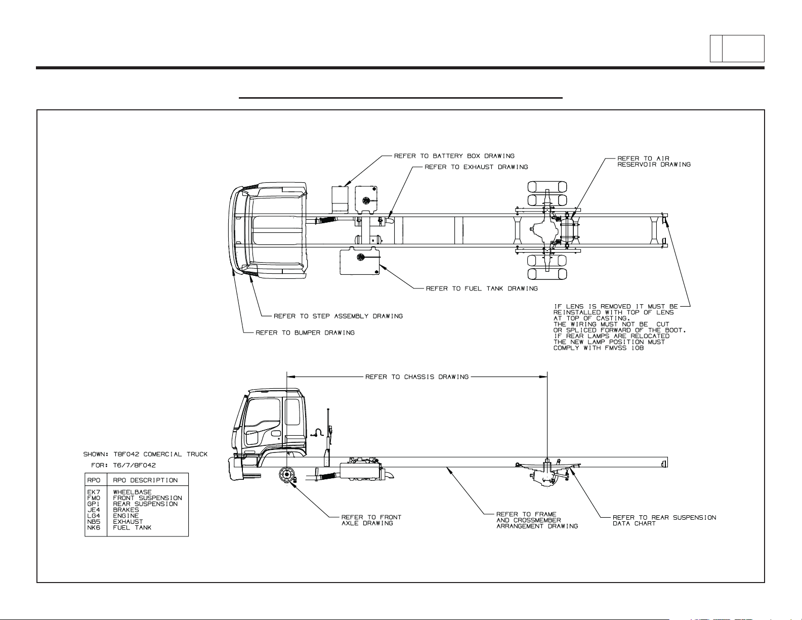
General Arrangement – T6/T7/T8 F042
Chevrolet/GMC Class T6500/7500/8500
& Isuzu Class FTR/FTV/FTX
2
PAGE
Low Cab Forward — Revised 10/2006
TD006041a
Page 6
Low Cab Forward
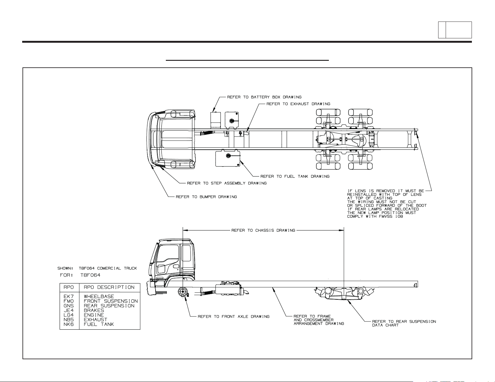
General Arrangement – T8F064
Chevrolet/GMC Class T6500/7500/8500
& Isuzu Class FTR/FTV/FTX
3
PAGE
Low Cab Forward — Revised 10/2006
TD006041b
Page 7
Low Cab Forward
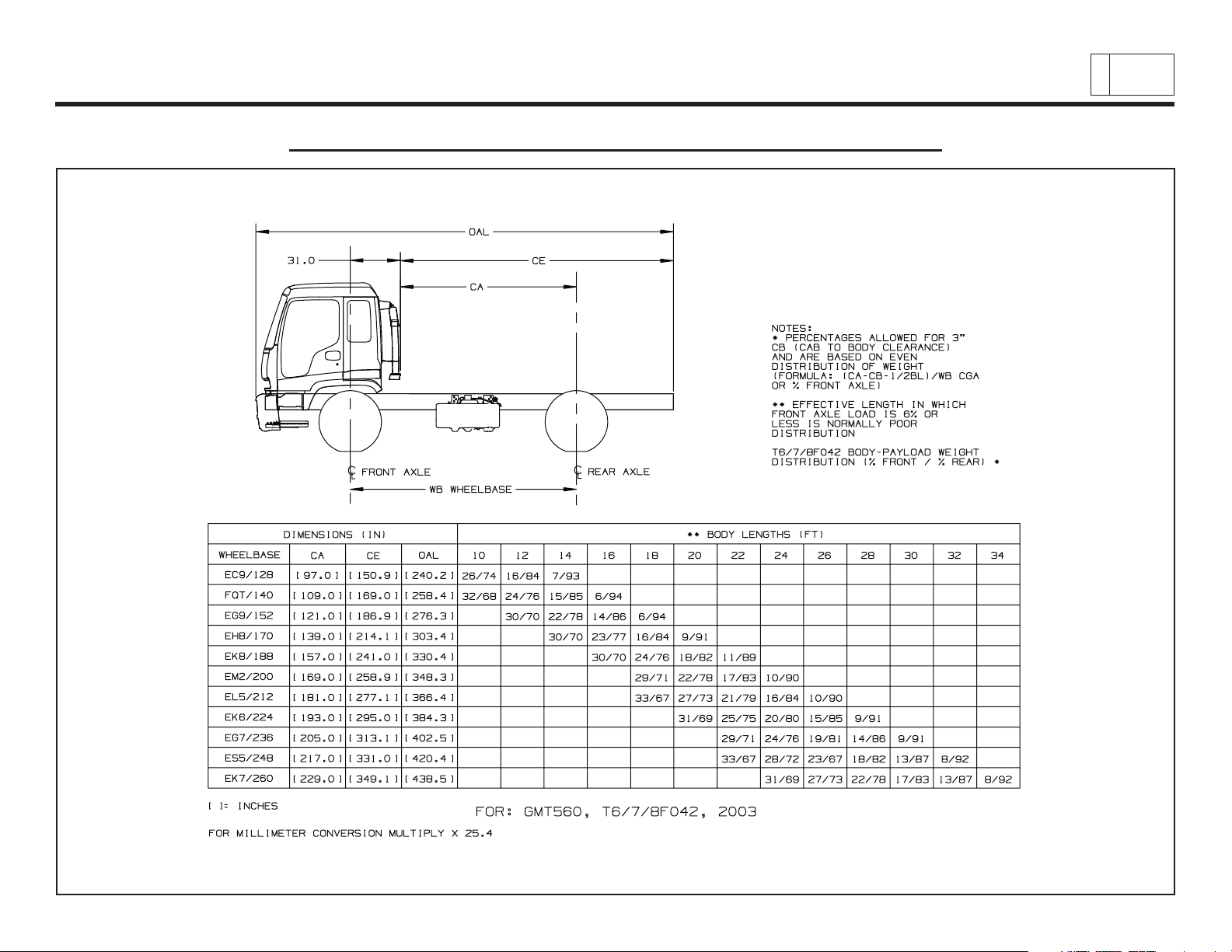
Body Payload Weight Distribution – T6/T7/T8 F042
Chevrolet/GMC Class T6500/7500/8500
& Isuzu Class FTR/FTV/FTX
4
PAGE
Low Cab Forward — Revised 10/2006
TD006055a
Page 8
Low Cab Forward
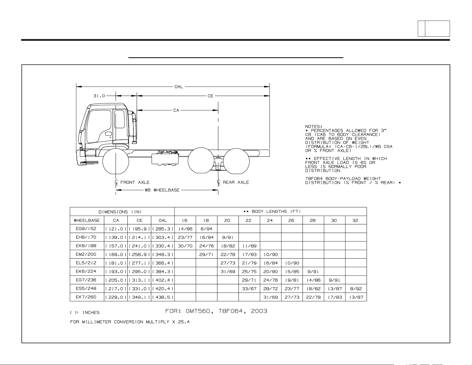
Body Payload Weight Distribution – T8F064
Chevrolet/GMC Class T6500/7500/8500
& Isuzu Class FTR/FTV/FTX
5
PAGE
Low Cab Forward — Revised 10/2006
TD006055b
Page 9
Sample Data:
Model Tire Tire Loaded Radius LH C D
T7F042
275/80R22.5G (XSH)
18.6" 9.69" 7.35" 5.75"
Frame Reinforcement RPO Wheelbase Suspension RPO Axle RPO
F20 152" (EG9) F28 (12,000 lb) FS7 (12,000 lb)
Formulas:
CH = C + Tire Static Loaded Radius + LH CH = 7.35" + 18.6" + 9.69" = 35.64"
DH = D + Tire Static Loaded Radius + LH DH = 5.75" + 18.6" + 9.69" = 34.04"
Definitions:
C – Centerline of axle to bottom inside of rail at curb position
D – Centerline of axle to bottom inside of rail at design load
LH – Distance from the bottom inside rail to the top of the rail
NOTE: For Tire, Static Loaded Radius (SLR) / QUICK LINKS – www.gmfleet.com /
See Medium Duty Online Order Guide / select Technical Data/Gray Tab from the upper tool bar /
select Wheel-Tire Specification / select print to view.
For the C & D values see the Front Axle and Suspension Chart.
For the LH values see the Frame Length with Reinforcements section.
Step Height Dimensions:
When calculating step height dimensions see the step assembly location, and the frame drawings for values.
R4L/S3L (Michelin) S4L
Low Cab Forward
Formulas for Calculating Height Dimensions to Top of Frame – Front Axle
Chevrolet/GMC Class T6500/7500/8500
& Isuzu Class FTR/FTV/FTX
6
PAGE
Low Cab Forward — Revised 10/2006
Page 10
Sample Data:
Model Tire Tire Loaded Radius LH C D
T7F042
275/80R22.5G (YSH)
19.0" 9.69" 11.41" 7.94"
S3H (Michelin) S4L
Frame Reinforcement RPO Wheelbase Suspension RPO Axle RPO
F20 152" (EG9) GNB (21,000 lb) HPN (21,000 lb)
F
ormulas:
CH = C + Tire Static Loaded Radius + LH CH = 19.0" + 11.41" + 9.69" = 40.11"
DH = D + Tire Static Loaded Radius + LH DH = 19.0" + 7.94" + 9.69" = 36.63"
D
efinitions:
C – Centerline of axle to bottom inside of rail at curb position
D – Centerline of axle to bottom inside of rail at design load
LH – Distance from the bottom inside rail to the top of the rail
NOTE: For Tire, Static Loaded Radius (SLR) / QUICK LINKS – www.gmfleet.com /
See Medium Duty Online Order Guide / select Technical Data/Gray Tab from the upper tool bar /
select Wheel-Tire Specification / select print to view.
For the C & D values see the Rear Axle and Suspension Chart.
For the LH values see the Frame Length with Reinforcements section.
Step Height Dimensions:
When calculating step height dimensions see the step assembly location, and the frame drawings for values.
Low Cab Forward
Formulas for Calculating Height Dimensions to Top of Frame – Rear Axle
Chevrolet/GMC Class T6500/7500/8500
& Isuzu Class FTR/FTV/FTX
7
PAGE
Low Cab Forward — Revised 10/2006
Page 11
Low Cab Forward
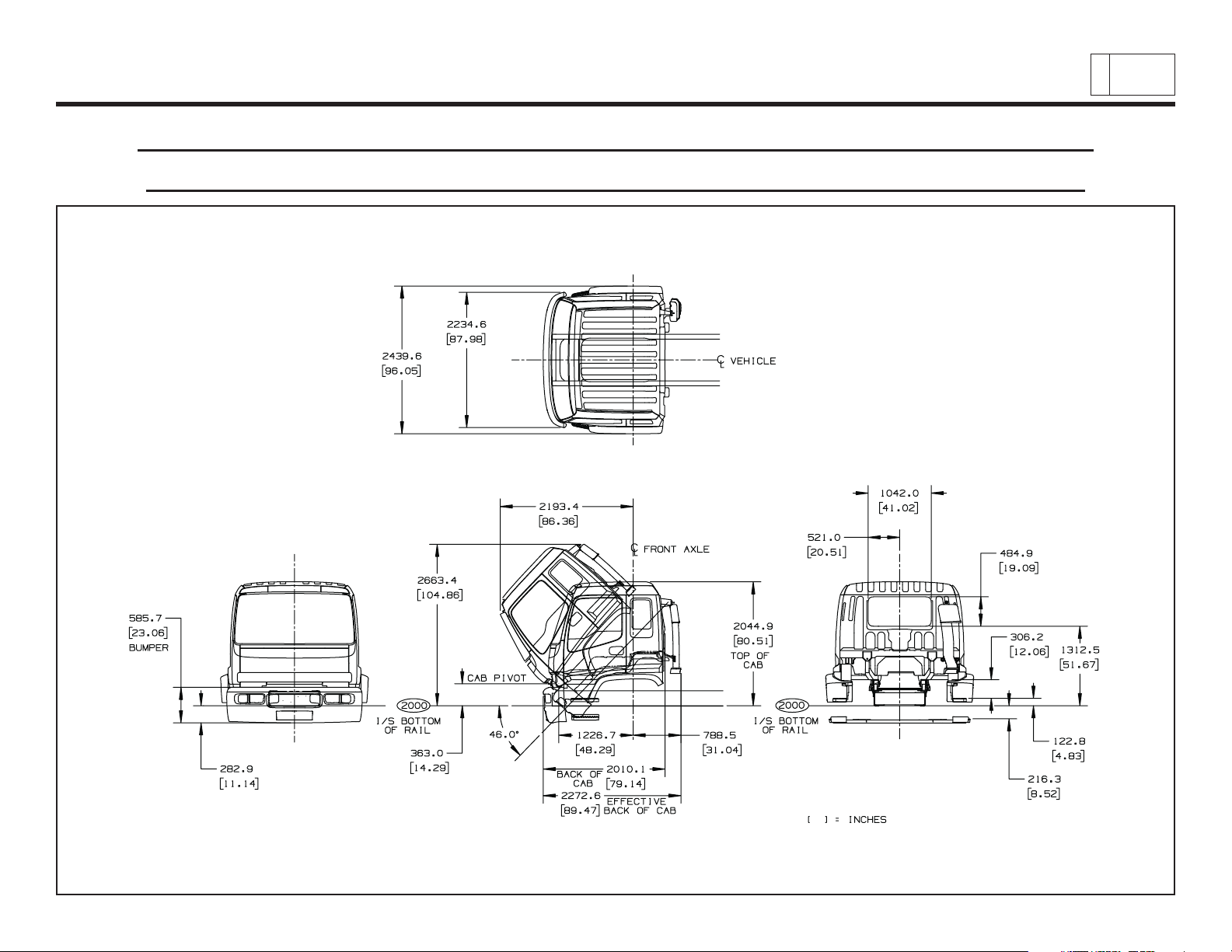
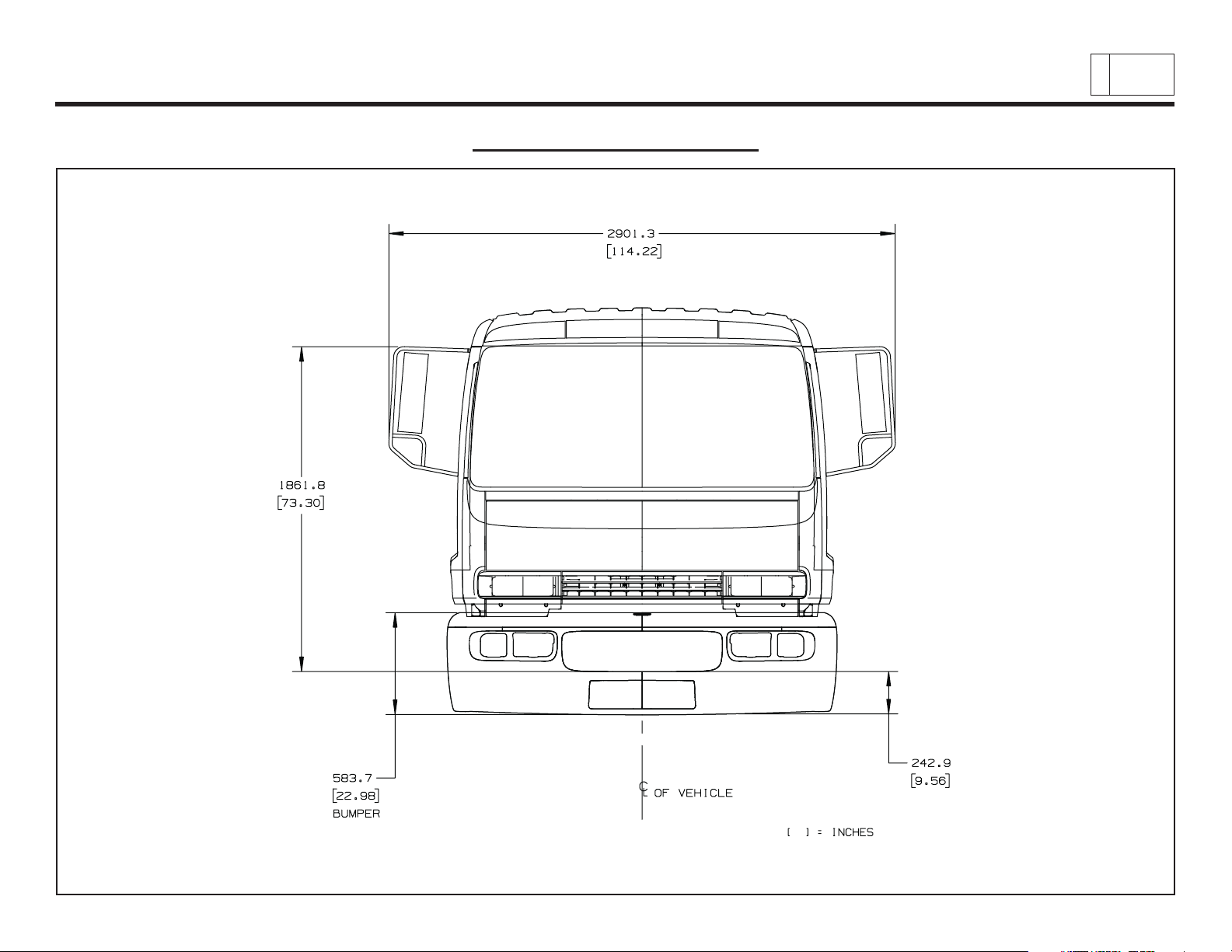
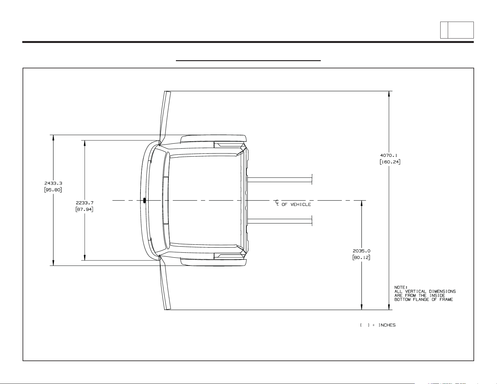
Cab Exterior – Front, Rear, Side Views – (Cab Tilt, Bumper, Rear Window,
Step Heights, Bumper To BOC, Bumper To Air Induction – Effective CA)
Chevrolet/GMC Class T6500/7500/8500
& Isuzu Class FTR/FTV/FTX
8
PAGE
Low Cab Forward — Revised 10/2006
TD006045a
Page 12
Low Cab Forward
Cab Exterior – Mirrors
Chevrolet/GMC Class T6500/7500/8500
& Isuzu Class FTR/FTV/FTX
9
PAGE
Low Cab Forward — Revised 10/2006
TD006045b
Page 13
Low Cab Forward
Cab Exterior – Door Swings
Chevrolet/GMC Class T6500/7500/8500
& Isuzu Class FTR/FTV/FTX
PAGE
10
Low Cab Forward — Revised 10/2006
TD006045c
Page 14
Low Cab Forward
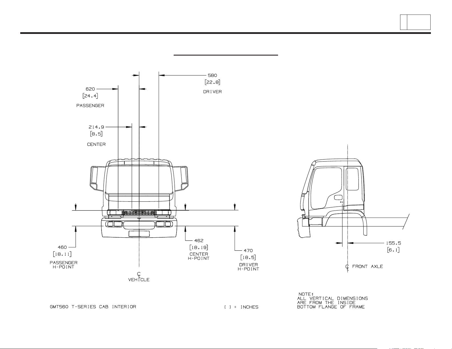
Cab Interior – Seating
Chevrolet/GMC Class T6500/7500/8500
& Isuzu Class FTR/FTV/FTX
PAGE
11
Low Cab Forward — Revised 10/2006
TD006044.3
Page 15

Chevrolet/GMC Class T6500/7500/8500
Low Cab Forward
& Isuzu Class FTR/FTV/FTX
General Information
Section Modulus
• Section modulus is a measure of the frame strength based solely on the height, width, thickness, and configuration of the side
rails. It is calculated at the point of maximum stress, which is usually directly behind the cab.
• Section modulus is not a measure of material strength and can only be used by itself to compare frames of like materials.
• Frame reinforcements will increase the section modulus because they increase the strength by adding to the thickness of the
section.
• Consult the Frame Properties for all section modulus ratings.
Yield Strength
• Yield strength is a measurement of the frame material’s strength. It is maximum load (PSI) that can be placed on the material and
still have it return to its original position when the load is removed without being bent out of shape.
• It can be used only to compare frames of identical section. Two yield strength frames are available for the T-Series. They are
80,000 psi (551,600 kPa) and 120,000 psi (827,400 kPa).
PAGE
12
RBM-Resisting Bending Moment
• Since Section Modulus can only be used to compare frames of like materials and yield strength can only indicate relative strengths
of identical frames, some measurement is necessary to compare frames of different materials and different sections. The RBM,
or Resisting Bending Moment, can be used for this comparison as it utilizes section modulus and yield strength in its makeup.
• RBM = Section Modulus x Yield Strength
• This measurement will show that a smaller section frame of higher strength steel will be just as strong as a larger section frame
of lower strength of steel.
• It is readily apparent that both section modulus and yield strength are equally important so that their product, RBM, is the correct
figure to use for frame comparisons. The RBMs for all standard and optional frames are shown on the Frame Properties charts.
• Frames are designed to torsional stiffness and beaming criteria as well as fatigue strength.
Low Cab Forward — Revised 10/2006
Page 16

Chevrolet/GMC Class T6500/7500/8500
Low Cab Forward
& Isuzu Class FTR/FTV/FTX
General Information (continued)
Frame Rail – Material and Weldability
• The frames on GM Trucks are built for strength, durability, and adaptability. They are available in tensile strengths of 80,000 psi
(551,600 kPa) and 120,000 psi (827,400 kPa) ratings.
• The 80,000 psi (551,600 kPa) frames are made from hot rolled steel that is pierced and formed to produce a finished side rail.
Following the procedure outlined in the GM Truck Service Manual these frames can be subjected to welding without affecting
frame integrity.
• The 120,000 psi (827,400 kPa) frame rails are made from steel with an initial yield strength of 35,000-40,000 psi. The chemistry
of the steel is slightly different to allow for better handling characteristic.Because the heat treating operation causes molecular
movement in the steel, the only holes pierced in the side rails prior to heat treating are near the front-end hole. Growth can be
predicted in this area and adjustments in hole placement can be made accordingly. The balance of the required holes are pierced
in the frame rail after heat treating.
• The 120,000 psi (827,400 kPa) frame rails are heat treated by an electric induction heat treating process. During this process,
the formed side rails are moved through a series of three induction coils and brought to a temperature of about 1650º F, (898.9º
C). Once at this temperature, the side rail passes through a cold-water quench. After the frame goes through the cold-water
quench, it is very hard but also brittle. Thus, the rails continue to roll through the final “tempering” electric coil and are brought to a
temperature of about 900º F, (482.2º C). Then the frame is allowed to cool to room temperature. This tempering operation “draws”
some of the hardness out of the material, but it now becomes very tough and durable. Once through the tempering operation, the
side rail passes through a “shot peen” operation. This process hurls millions of 1/8-inch, (0.3175 cm), diameter spherical-shaped
balls at the side rails. Shot peening significantly increases the fatigue life of the frame rail, as well as providing a clean surface.
PAGE
13
• Welding should not be preformed on the heat treated 120,000 psi (827,400 kPa) frame rails. Welding depends on heat for a good
adherence. Applying heat or welding on hardened side rails will create a “soft zone” where the heat was applied. Since the heated
area is now softer than the balance of the side rail, the general area would become more susceptible to failure of the frame rail.
Low Cab Forward — Revised 10/2006
Page 17

Chevrolet/GMC Class T6500/7500/8500
Low Cab Forward
& Isuzu Class FTR/FTV/FTX
General Information (continued)
Body Mounting Concerns
• The great variety of truck bodies and applications is difficult to appreciate. GM has tried to offer frame equipment suitable for the
greatest number of configurations, but some concerns do exist. To assist sales personnel and customers, we remind everyone
to review and follow data presented in:
• TRUCK BODY BUILDER BOOK Located at gmupfitter.com
• SERVICE MANUAL
• OWNERS MANUAL
• Each publication contributes to an understanding of the complex issues of good vehicle / body application.
• The amount of load carried by the front axle is the most significant consideration. Front Gross Axle Weight Ratings (FGAWR) are
sometimes controlled by the frame.
• The front frame limit is defined by wheelbase and frame choice for each model. The attachment method and the structural
character of the body will also affect the final vehicle performance.
PAGE
14
• Based on experience, GM has determined that
Back-of-Cab. This will assure that ride, handling and load carrying ability are maintained for high customer satisfaction.
Single Axle Medium Duty Conventional
• T6500 single-axle model frames feature straight full-channel side rails over the total length of the frame. Channel type
crossmembers are web mounted to leave side rail flanges clear for body mounting.
• T7500 single-axle model frames are similar to the T6500 frames.
• Optional heat-treated sidemembers (F06) are also available on T7500 truck (RQ2) models.
• “L” shaped reinforcements are available to increase the section modulus.
• Heat-treated sidemembers (F06) and “L” shaped reinforcements are standard for tractor (RQ3).
• Rear side rail taper is standard for tractor.
Low Cab Forward — Revised 10/2006
the first body mounting point should be within 12 inches or (30.5 cm) of the
Page 18

Chevrolet/GMC Class T6500/7500/8500
Low Cab Forward
& Isuzu Class FTR/FTV/FTX
General Information (continued)
Strength
• The frame has a straight, full-depth, C-shaped side member rail design and a ladder-type frame assembly.
• The overall frame length on sizes similar to those previously offered has increased by about 1 inch or (2.54 cm) to accommodate
a slight increase in front overhang (related to improved aerodynamics and visibility).
• Basic frame dimensions.
• The T6500-T7500 Series models (unlike the 4500-5500 Series) allow customers to select the frame strength they want and tailor
it to their particular requirements.
• The (RPO F05) 8mm thick frame with 80,000 psi (551,600 kPa), strength is available on all single-axle trucks. Because of its
widespread availability and strength, it has, by far, been the most popular choice, accounting for nearly 80 percent of total frame
selection.
• The (RPO F06) 8mm thick frame with 120,000 psi (827,400 kPa) strength is available on all wheelbase models. It is now also
the standard frame for the tandem axle models and tractor models. This provides more value (extra strength) for customers and
simplifies manufacturing for GM.
• The frame crossmembers all have a 50,000 psi (344,750 kPa) material strength. Their thickness varies, depending on their
application.
PAGE
15
• Customers can also choose frame reinforcements for extra strength to meet their GVW/gross axle weight rating (GAWR) needs.
• The reinforcements can make a considerable difference in front axle loading capability. For example, if a customer selects a 224inch (569 cm) wheelbase and (RPO F05) frame, the maximum load rating allowed on the front is 12,000 pounds (5443 kg). Adding
the L-shaped frame reinforcement option increases front axle load rating 14,600 pounds (6622 kg).
• Basically, the “L” shaped reinforcement gives the 8mm-thick/80,000-psi frame a front axle load rating equal to a 8mm thick/
120,000 psi (827,400 kPa) strength frame.
• The T6500-T7500 Series offer two frame reinforcements. Both have the “L” shaped (with the flange at the bottom) to fit this Series'
particular design requirements. Both are also 8mm thick.
• (RPO F08) and (RPO FSA) with 80,000 psi (551,600 kPa) strength “L” shaped reinforcement on the T6500-T7500 single-axle truck
models.
• (RPO F20) and (RPO FSC) which are made of heated treated material to match the heat-treated frame option.
• RPO F08 and F20 start under the cab and run to approximately the rear of the rear spring hanger.
• RPO FSA and FSC start under the cab and run to the end of the rail.
Low Cab Forward — Revised 10/2006
Page 19

Low Cab Forward
Chevrolet/GMC Class T6500/7500/8500
& Isuzu Class FTR/FTV/FTX
PAGE
16
Frame Material Properties
T6500 & T7500 Single-Axle Truck Models T7500 Models
Frame Material and Physical Properties Frame RPO “F05” Frame RPO “F06”
Material Steel No. or Type SAE J1392 (-080 XLF) H.T. SAE 1027
Material Thickness – in. (mm) 0.32 (8) 0.32 (8)
Physical Properties:
Min. Tensile or Ultimate Strength psi (kPa) 95,000 (655,000) 125,000 (861,800)
Minimum Yield Strength psi (kPa) 80,000 (551,600) 120,000 (827,400)
Resisting Bending Moment (RBM)
(Rated Yield Strength x Section Modulus) 80,000 x SM 120,000 x SM
Section Modulus in
Rated RBM 1,015,000 1,522,800
Optional Reinforcement RPO F08 or FSA F20 or FSC
Reinforcement Type “L” Shape “L” Shape
Material Thickness – in. (mm) 0.32 (8) 0.32 (8)
Combined Section in
Rated Combined RBM 1,938,000 2,907,600
* Grade 80 is rated equivalent to Heat Treated SAE 1027
**SECTION MODULUS BASED ON Square C-Channel. (Actual parts contain radius)
110K Heat Treated Versus 80K HSLA
GM Truck is the only major OEM to offer 80K HLSA material on all T-Series.
This offering is based on fatigue testing which shows equivalency to heat treated steel.
Frames fail in fatigue, not yield, and therefore the materials are equivalent with respect to service life.
3
(cm3) 12.69 (208) 12.69 (208)
Frame Reinforcements Available
3
(cm3) 24.23 (397) 24.23 (397)
Low Cab Forward — Revised 10/2006
Page 20

Low Cab Forward
Frame Lengths with Reinforcements
Chevrolet/GMC Class T6500/7500/8500
& Isuzu Class FTR/FTV/FTX
PAGE
17
Low Cab Forward — Revised 10/2006
TD006051a
Page 21

Low Cab Forward
Frame Lengths with Reinforcements – Charts (042)
Chevrolet/GMC Class T6500/7500/8500
& Isuzu Class FTR/FTV/FTX
PAGE
18
Low Cab Forward — Revised 10/2006
TD006051b
Page 22

Low Cab Forward
Frame Lengths with Reinforcements – Charts (064)
Chevrolet/GMC Class T6500/7500/8500
& Isuzu Class FTR/FTV/FTX
PAGE
19
Low Cab Forward — Revised 10/2006
TD006051c
Page 23

Low Cab Forward
Frame and Crossmember Locations (042)
Chevrolet/GMC Class T6500/7500/8500
& Isuzu Class FTR/FTV/FTX
PAGE
20
Low Cab Forward — Revised 10/2006
TD006046.3
Page 24

Low Cab Forward
Frame and Crossmember Locations (064)
Chevrolet/GMC Class T6500/7500/8500
& Isuzu Class FTR/FTV/FTX
PAGE
21
Low Cab Forward — Revised 10/2006
TD0060464.4
Page 25

Low Cab Forward
Front Axle Track and Suspension Drawing
Chevrolet/GMC Class T6500/7500/8500
& Isuzu Class FTR/FTV/FTX
PAGE
22
Low Cab Forward — Revised 10/2006
TD006059a
Page 26

Low Cab Forward
Front Axle Track Charts
Chevrolet/GMC Class T6500/7500/8500
& Isuzu Class FTR/FTV/FTX
PAGE
23
Low Cab Forward — Revised 10/2006
TD006059.4
Page 27

Low Cab Forward
Front Suspension Charts
Chevrolet/GMC Class T6500/7500/8500
& Isuzu Class FTR/FTV/FTX
PAGE
24
Low Cab Forward — Revised 10/2006
TD006059.5
Page 28

Low Cab Forward
Rear Axle and Suspension – Drawing (042)
Chevrolet/GMC Class T6500/7500/8500
& Isuzu Class FTR/FTV/FTX
PAGE
25
Low Cab Forward — Revised 10/2006
TD006060a
Page 29

Low Cab Forward
Rear Axle and Suspension – Formulas (042)
Chevrolet/GMC Class T6500/7500/8500
& Isuzu Class FTR/FTV/FTX
PAGE
26
Low Cab Forward — Revised 10/2006
TD006060b
Page 30

Chevrolet/GMC Class T6500/7500/8500
27
Low Cab Forward
& Isuzu Class FTR/FTV/FTX
PAGE
Rear Axle / Suspension – Chart (042) Option Description and Bottom of Differential Bowl
Low Cab Forward — Revised 10/2006
TD006060.5
Page 31

Low Cab Forward
Rear Axle / Wheel – Chart (042) Track Widths
Chevrolet/GMC Class T6500/7500/8500
& Isuzu Class FTR/FTV/FTX
PAGE
28
Low Cab Forward — Revised 10/2006
TD006060.6
Page 32

Low Cab Forward
Rear Axle / Suspension – Chart (042) Heights
Chevrolet/GMC Class T6500/7500/8500
& Isuzu Class FTR/FTV/FTX
PAGE
29
Low Cab Forward — Revised 10/2006
TD006060.7
Page 33

Low Cab Forward
Rear Axle / Suspension – Chart (042) Heights
Chevrolet/GMC Class T6500/7500/8500
& Isuzu Class FTR/FTV/FTX
PAGE
30
Low Cab Forward — Revised 10/2006
TD006060f
Page 34

Low Cab Forward
Rear Axle and Suspension – Drawing (064)
Chevrolet/GMC Class T6500/7500/8500
& Isuzu Class FTR/FTV/FTX
PAGE
31
Low Cab Forward — Revised 10/2006
TD006047a
Page 35

Low Cab Forward
Rear Axle and Suspension – Formulas (064)
Chevrolet/GMC Class T6500/7500/8500
& Isuzu Class FTR/FTV/FTX
PAGE
32
Low Cab Forward — Revised 10/2006
TD006047b
Page 36

Chevrolet/GMC Class T6500/7500/8500
33
Low Cab Forward
& Isuzu Class FTR/FTV/FTX
PAGE
Rear Axle / Suspension – Chart (064) Option Descriptions, Bottom of Differential Bowl and Heights
Low Cab Forward — Revised 10/2006
TD006047c
Page 37

Low Cab Forward
Air Tank Location – (042) Truck – RQ2
Chevrolet/GMC Class T6500/7500/8500
& Isuzu Class FTR/FTV/FTX
PAGE
34
Low Cab Forward — Revised 10/2006
TD006043a
Page 38

Low Cab Forward
Air Tank Location – (042) Tractor – RQ3
Chevrolet/GMC Class T6500/7500/8500
& Isuzu Class FTR/FTV/FTX
PAGE
35
Low Cab Forward — Revised 10/2006
TD006043b
Page 39

Low Cab Forward
Air Tank Location – (064) Truck – RQ2
Chevrolet/GMC Class T6500/7500/8500
& Isuzu Class FTR/FTV/FTX
PAGE
36
Low Cab Forward — Revised 10/2006
TD006043c
Page 40

Low Cab Forward
Air Tank Location – (064) Tractor – RQ3
Chevrolet/GMC Class T6500/7500/8500
& Isuzu Class FTR/FTV/FTX
PAGE
37
Low Cab Forward — Revised 10/2006
TD006043d
Page 41

Low Cab Forward
BATTERY BOX LOCATION
Chevrolet/GMC Class T6500/7500/8500
& Isuzu Class FTR/FTV/FTX
PAGE
38
Low Cab Forward — Revised 10/2006
TD006042a
Page 42

Low Cab Forward
Dual 50 Gallon (opt. NJ8) & Single 50 Gallon LH (opt. NK8)
Chevrolet/GMC Class T6500/7500/8500
& Isuzu Class FTR/FTV/FTX
PAGE
39
Low Cab Forward — Revised 11/2007
TD006056.3
Page 43

Chevrolet/GMC Class T6500/7500/8500
Low Cab Forward
& Isuzu Class FTR/FTV/FTX
Dual 50 Gallon LH and 25 Gallon RH (opt. NJ7) & Single 50 Gallon LH (opt. NK6)
PAGE
40
Low Cab Forward — Revised 11/2007
TD006056.4
Page 44

Low Cab Forward
Chevrolet/GMC Class T6500/7500/8500
& Isuzu Class FTR/FTV/FTX
AIR INDUCTION
PAGE
41
Low Cab Forward — Revised 10/2006
TD006057a
Page 45

Chevrolet/GMC Class T6500/7500/8500
Low Cab Forward
& Isuzu Class FTR/FTV/FTX
Single Horizontal Exhaust w/RH exit tailpipe & cooler, opt. N1B & 7.8 Isuzu Diesel LHP & 140´´ WB opt.
PAGE
42
Low Cab Forward — Revised 08/2007
AND20446.19
Page 46

Low Cab Forward
Chevrolet/GMC Class T6500/7500/8500
& Isuzu Class FTR/FTV/FTX
PAGE
43
Single Horizontal Exhaust w/RH exit tailpipe & cooler, opt. N1B & 7.8 Isuzu Diesel HHP & 140´´ WB opt. FQT
Low Cab Forward — Revised 08/2007
AND20446.18
Page 47

Chevrolet/GMC Class T6500/7500/8500
Low Cab Forward
& Isuzu Class FTR/FTV/FTX
Single Horizontal Exhaust, opt. NB5 & 7.8 Isuzu Diesel LHP & 152´´ and longer WB
PAGE
44
Low Cab Forward — Revised 05/2007
AND20446.17
Page 48

Chevrolet/GMC Class T6500/7500/8500
Low Cab Forward
& Isuzu Class FTR/FTV/FTX
Single Horizontal Exhaust, opt. NB5 & 7.8 Isuzu Diesel HHP & 152´´ and longer WB
PAGE
45
Low Cab Forward — Revised 05/2007
AND20446.16
Page 49

Low Cab Forward
Exhaust LH Vertical DPF, Tailpipe and Heat Shield –
Exhaust opt. NEP, with Engine opt. LF8, 7.8L LHP Isuzu
Chevrolet/GMC Class T6500/7500/8500
& Isuzu Class FTR/FTV/FTX
PAGE
46
Low Cab Forward — Revised 08/2007
AND20446.21
Page 50

Low Cab Forward
Exhaust LH Vertical DPF, Tailpipe and Heat Shield –
Exhaust opt. NEP, with Engine opt. LF8, 7.8L HHP Isuzu
Chevrolet/GMC Class T6500/7500/8500
& Isuzu Class FTR/FTV/FTX
PAGE
47
Low Cab Forward — Revised 08/2007
AND20446.20
Page 51

Chevrolet/GMC Class T6500/7500/8500
Low Cab Forward
& Isuzu Class FTR/FTV/FTX
Exhaust LH Vertical DPF, Tailpipe and Heat Shield – Option LF8, 7.8L LHP Isuzu
PAGE
48
Low Cab Forward — Revised 05/2007
AND20446.22
Page 52

Low Cab Forward
Manual Transmission PTO Location Charts
Chevrolet/GMC Class T6500/7500/8500
& Isuzu Class FTR/FTV/FTX
PAGE
49
Low Cab Forward — Revised 05/2007
AND77068.8
Page 53

Low Cab Forward
Automatic Transmission PTO Location Charts
Chevrolet/GMC Class T6500/7500/8500
& Isuzu Class FTR/FTV/FTX
PAGE
50
Low Cab Forward — Revised 05/2007
AND77068.9
 Loading...