

Page 1

For DENSO Authorized
ECD Service Dealer Only
Diesel Injection Pump
No. E-03-04
SERVICE MANUAL
Common Rail System for OPEL
4EE2 Type Engine
Operation
August, 2003
-1
00400028
Page 2

FORWARD
To meet the high pressurization requirements for the engine to deliver cleaner exhaust gas
emissions, lower fuel consumption and reduced noise, advanced electronic control technology
is being adopted in the fuel injection system.
This manual covers the electronic control model Common Rail system with HP3 pump for the
ISUZU 4EE2 type engine which is used to OPEL CORSA and MERIVA. Complex theories, special functions and components made by manufacturers other than DENSO are omitted from this
manual.
This manual will help the reader develop an understanding of the basic construction, operation
and system configuration of the DENSO manufactured components and brief diagnostic information.
TABLE OF CONTENTS
1. Product Application ----------------------------------------------------------------------------------- 1
1.1 Application ----------------------------------------------------------------------------------------------------------------1
1.2 System Components Parts Numbers ------------------------------------------------------------------------------ 1
2. Outline ---------------------------------------------------------------------------------------------------- 2
2.1 Features of System ----------------------------------------------------------------------------------------------------- 2
[1] System Characteristics --------------------------------------------------------------------------------------------- 2
[2] Comparison to the Conventional System ----------------------------------------------------------------------- 3
2.2 Outline of System ------------------------------------------------------------------------------------------------------- 4
[1] Composition ----------------------------------------------------------------------------------------------------------- 4
[2] Operation --------------------------------------------------------------------------------------------------------------- 4
[3] Fuel System ------------------------------------------------------------------------------------------------------------ 5
[4] Control System -------------------------------------------------------------------------------------------------------- 5
3. Construction and Operation------------------------------------------------------------------------- 6
3.1 Description of Main Components ----------------------------------------------------------------------------------- 6
[1] Supply Pump (HP3) -------------------------------------------------------------------------------------------------- 6
[2] Description of Supply Pump Components ---------------------------------------------------------------------- 11
[3] Rail -----------------------------------------------------------------------------------------------------------------------14
[4] Injector ------------------------------------------------------------------------------------------------------------------ 16
3.2 Description of Control System Components --------------------------------------------------------------------- 19
[1] ECU (Electronic Control Unit) ------------------------------------------------------------------------------------- 19
[2] Description of Sensors ---------------------------------------------------------------------------------------------- 19
[3] EGR Valve (Exhaust Gas Recirculation Valve) --------------------------------------------------------------- 21
3-3 Various Types of Controls --------------------------------------------------------------------------------------------- 22
[1] Outline ------------------------------------------------------------------------------------------------------------------- 22
[2] Fuel Injection Quantity Control ------------------------------------------------------------------------------------ 23
[3] Fuel Injection Timing Control -------------------------------------------------------------------------------------- 25
[4] Fuel Injection Rate Control ----------------------------------------------------------------------------------------- 26
[5] Fuel Injection Pressure Control ----------------------------------------------------------------------------------- 26
[6] Other Controls --------------------------------------------------------------------------------------------------------- 26
4. External Wiring Diagram ----------------------------------------------------------------------------- 27
4.1 ECU External Wiring Diagram --------------------------------------------------------------------------------------- 27
4.2 ECU Connector Diagram ---------------------------------------------------------------------------------------------- 29
[1] ECU Connector Terminal Layout --------------------------------------------------------------------------------- 29
[2] Terminal Connections ----------------------------------------------------------------------------------------------- 29
0
Page 3

1. Product Application
1.1 Application
Vehicle Name Vehicle Model Engine Model Exhaust Volume Reference
Corsa S-Car
4EE2 1.7L Made in Germany
Meriva S-Mono
1.2 System Components Parts Number
Vehicle Model
Part Name
Corsa Meriva
DENSO Part
Number
Car Manufacturer
Part Number
Supply Pump {{HU294000-0071 97313 862
Rail {{HU095440-0411 97313 863
Injector {{HU095000-5082 97313 861
{ 112500-0151 97300 097
Engine ECU
{ 112500-0161 97350 948
Supply use 112500-0170 97364 132
Crankshaft Position Sensor {{949979-1200 97321 620
Cylinder Recognition Sensor {{949979-1200 97321 620
EGR Valve {{HU135000-7040 97355 042
1
Page 4

2. Outline
2.1 Outline of System
The common rail system was developed primarily to cope with exhaust gas regulations for diesel engines, and aimed for 1. further improved fuel economy; 2. noise reduction; and 3. high
power output.
[1] System Characteristics
The common rail system uses a type of accumulation chamber called a rail to store pressurized
fuel, and injectors that contain electronically controlled solenoid valves to spray the pressurized
fuel into the cylinders. Because the engine ECU controls the injection system (including the injection pressure, injection rate, and injection timing), the injection system is unaffected by the
engine speed or load. This ensures a stable injection pressure at all times, particularly in the
low engine speed range, and dramatically decreases the amount of black smoke ordinarily
emitted by a diesel engine during start-up and acceleration. As a result, exhaust gas emissions
are cleaner and reduced, and higher power output is achieved.
(1) Injection pressure control
• Enables high-pressure injection even at low engine speeds.
• Optimizes control to minimize particulate matter and NOx emissions.
(2) Injection timing control
Enables finely tuned optimized control in accordance with driving conditions.
(3) Injection rate control
Pilot injection control sprays a small amount of fuel before the main injection.
Common Rail System
Injection Pressure Control
Optimization, High pressurization
Common rail system
Conventional
Injection pressure
pump
Speed
Particulate
Injection
pressure
Injection Timing Control
Optimization
Common rail system
NOx
Injection timing
Conventional
pump
Speed
Injection Rate Control
Injection rate
Crankshaft angle
Injection Quantity Control
Cylinder injection
volume correction
Speed
㧝㧟㧠㧞
Pilot injection
Main
injection
QD0734E
2
Page 5

[2] Comparison to the Conventional System
In-line, VE Pump
High-pressure pipe
Momentary high pressure
Timer
System
In-line pump
VE pump
Injection quantity control
Injection timing control
Pump (governor)
Pump (timer)
Rising pressure
Distributor Pump
Injection pressure control
Dependent upon speed and injection quantity
Governor
Pump
Common rail system
Rail
TWV
Nozzle
Supply pump
Usually high pressure
Delivery valve
Feed pump
SCV (suction control valve)
Injector
Fuel tank
Engine ECU, injector (TWV)*
Engine ECU, injector (TWV)*
1
1
Engine ECU, supply pump
Engine ECU, rail
Engine ECU, supply pump (SCV)*
2
*1 TWV: Two Way Valve *2 SCVSuction Control Valve
QD2341E
3
Page 6

2.2 Outline of System [1] Composition
The common rail system consists primarily of a supply pump, rail, injectors, and engine ECU.
Fuel temperature sensor
Vehicle speed
Accelerator opening
Intake air pressure
Intake air temperature
Coolant temperature
Crankshaft position
Cylinder recognition sensor
Engine ECU
Intake airflow rate
Fuel temperature
sensor
Rail pressure
sensor
Supply pump
Rail
SCV (suction
control valve)
Pressure
limiter
Fuel tank
Injector
Q000144E
[2] Operation
(1) Supply pump (HP3)
The supply pump draws fuel from the fuel tank, and pumps the high pressure fuel to the rail.
The quantity of fuel discharged from the supply pump controls the pressure in the rail. The
SCV (Suction Control Valve) in the supply pump effects this control in accordance with the
command received from the ECU.
(2) Rail
The rail is mounted between the supply pump and the injector, and stores the high-pressure
fuel.
(3) Injector
This injector replaces the conventional injection nozzle, and achieves optimal injection by effecting control in accordance with signals from the ECU. Signals from the ECU determine
the length of time and the timing in which current is applied to the injector. This in turn, determines the quantity, rate and timing of the fuel that is injected from the injector.
(4) Engine ECU
The engine ECU calculates data received from the sensors to comprehensively control the
injection quantity, timing and pressure, as well as the EGR (exhaust gas recirculation).
4
Page 7

[3] Fuel System
This system comprises the route through which diesel fuel flows from the fuel tank to the supply
pump, via the rail, and is injected through the injector, as well as the route through which the
fuel returns to the tank via the overflow pipe.
[4] Control System
In this system, the engine ECU controls the fuel injection system in accordance with the signals
received from various sensors. The components of this system can be broadly divided into the
following three types: (1) Sensors; (2) ECU; and (3) Actuators.
(1) Sensors
Detect the engine and driving conditions, and convert them into electrical signals.
(2) Engine ECU
Performs calculations based on the electrical signals received from the sensors, and sends
them to the actuators in order to achieve optimal conditions.
(3) Actuators
Operate in accordance with electrical signals received from the ECU. Injection system control is undertaken by electronically controlling the actuators. The injection quantity and timing
are determined by controlling the duration and the timing in which the current is applied to
the TWV (Two-Way Valve) in the injector. The injection pressure is determined by controlling
the SCV (Suction Control Valve) in the supply pump.
Sensor
Crankshaft Position Sensor (NE)
Cylider recognition sensor (G)
Accelerator position sensor
Other sensors and switches
Engine speed
Cylinder recognition
Load
Actuator
Injector
•Injection quantity control
•Injection timing control
•Injection pressure control
Engine
ECU
Supply pump (SCV)
•Fuel pressure control
EGR, air intake control relay, light
Q000047E
5
Page 8

3. Construction and Operation
3.1 Description of Main Components [1] Supply Pump (HP3)
(1) Outline
• The supply pump consists primarily of the pump body (eccentric cam, ring cam, and plungers),
SCV (Suction Control Valve), fuel temperature sensor, and feed pump.
Fuel temperature sensor
SCV (Suction Control Valve)
Q000145E
• The two plungers are positioned vertically on the outer ring cam for compactness.
• The engine drives the supply pump at a ratio of 1:2. The supply pump has a built-in feed
pump (trochoid type), and draws the fuel from the fuel tank, sending it to the plunger
chamber.
• The internal camshaft drives the two plungers, and they pressurize the fuel sent to the plunger
chamber and send it to the rail. The quantity of fuel supplied to the rail is controlled by the SCV,
using signals from the engine ECU. The SCV is a normally opened type (the intake valve
opens during de-energization).
6
Page 9

Injector
Rail
Return
Fuel overflow
Discharge valve
Intake valve
Plunger
Intake pressure
Feed pressure
High pressure
Return pressure
Return spring
Regulating valve
Fuel tank
Camshaft
Filter
Feed pump
Fuel inlet
Intake
Fuel filter (with priming pump)
QD0704E
7
Page 10

Pump body
Ring cam
SCV
Feed pump
Regulating valve
Filter
Drive shaft
Plunger
Q000146E
8
Page 11

(2) Supply Pump Internal Fuel Flow
The fuel that is drawn from the fuel tank passes through the route in the supply pump as illustrated, and is fed into the rail.
Supply pump interior
Regulating valve
Feed pump
Overflow
Fuel tank
SCV (Suction Control Valve)
Intake valve
Discharge valve
Pumping portion (plunger)
Rail
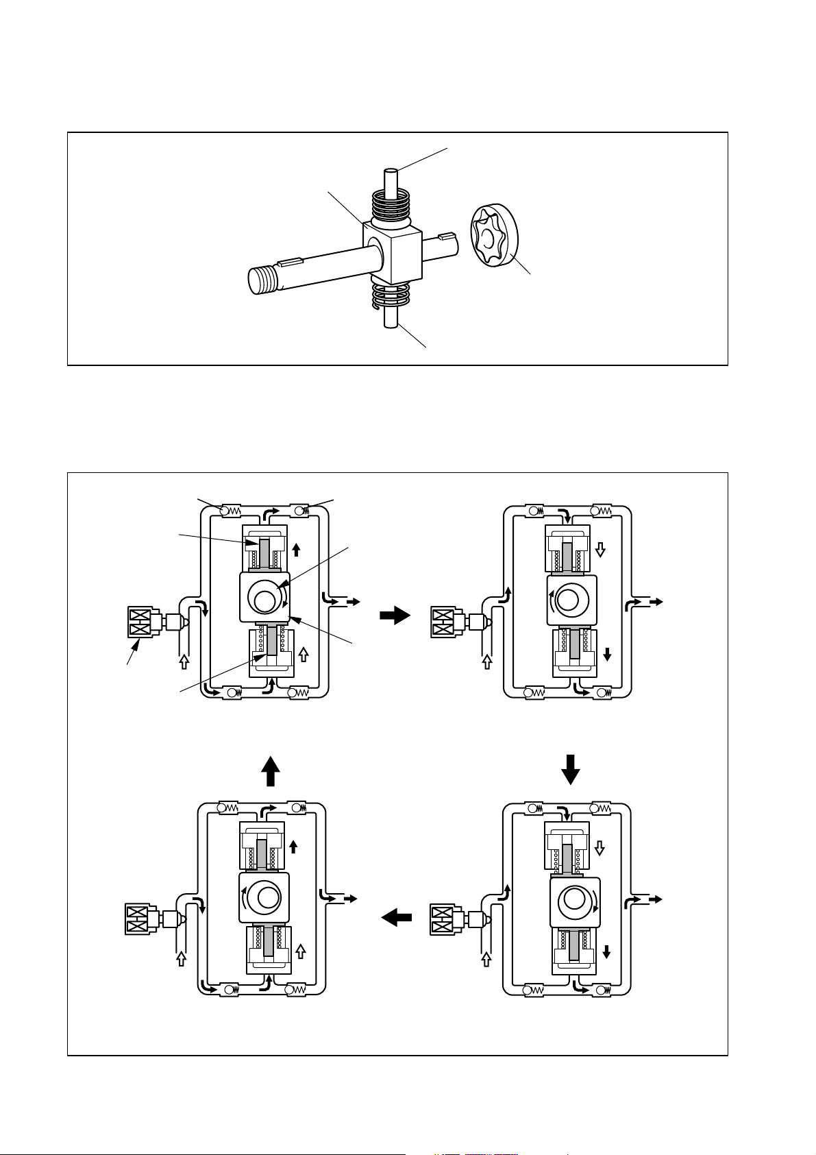
(3) Construction of Supply Pump
The eccentric cam is formed on the drive shaft. The ring cam is connected to the eccentric cam.
Drive shaft
Eccentric cam
Ring cam
As the drive shaft rotates, the eccentric cam rotates in the eccentric state, and the ring cam
moves up and down while rotating.
Plunger
QD0705E
QD0706E
Eccentric cam
Drive shaft
Ring cam
QD0727E
9
Page 12
The plunger and the suction valve are mounted on top of the ring cam. The feed pump is connected to the rear of the drive shaft.
Plunger A
Ring cam
Feed pump
Plunger B
(4) Operation of the Supply Pump
As shown in the illustration below, the rotation of the eccentric cam causes the ring cam to
push Plunger A upwards. Due to the spring force, Plunger B is pulled in the opposite direction
to Plunger A. As a result, Plunger B draws in fuel, while Plunger A pumps it to the rail.
Suction valve
Plunger A
SCV
Plunger B
Plunger A: complete compression
Plunger B: complete intake
Delivery valve
Eccentric cam
Ring cam
Plunger A: begin intake
Plunger B: begin compression
QD0728E
Plunger A: begin compression
Plunger B: begin intake
Plunger A: complete intake
Plunger B: complete compression
QD0707E
10
Page 13
[2] Description of Supply Pump Components
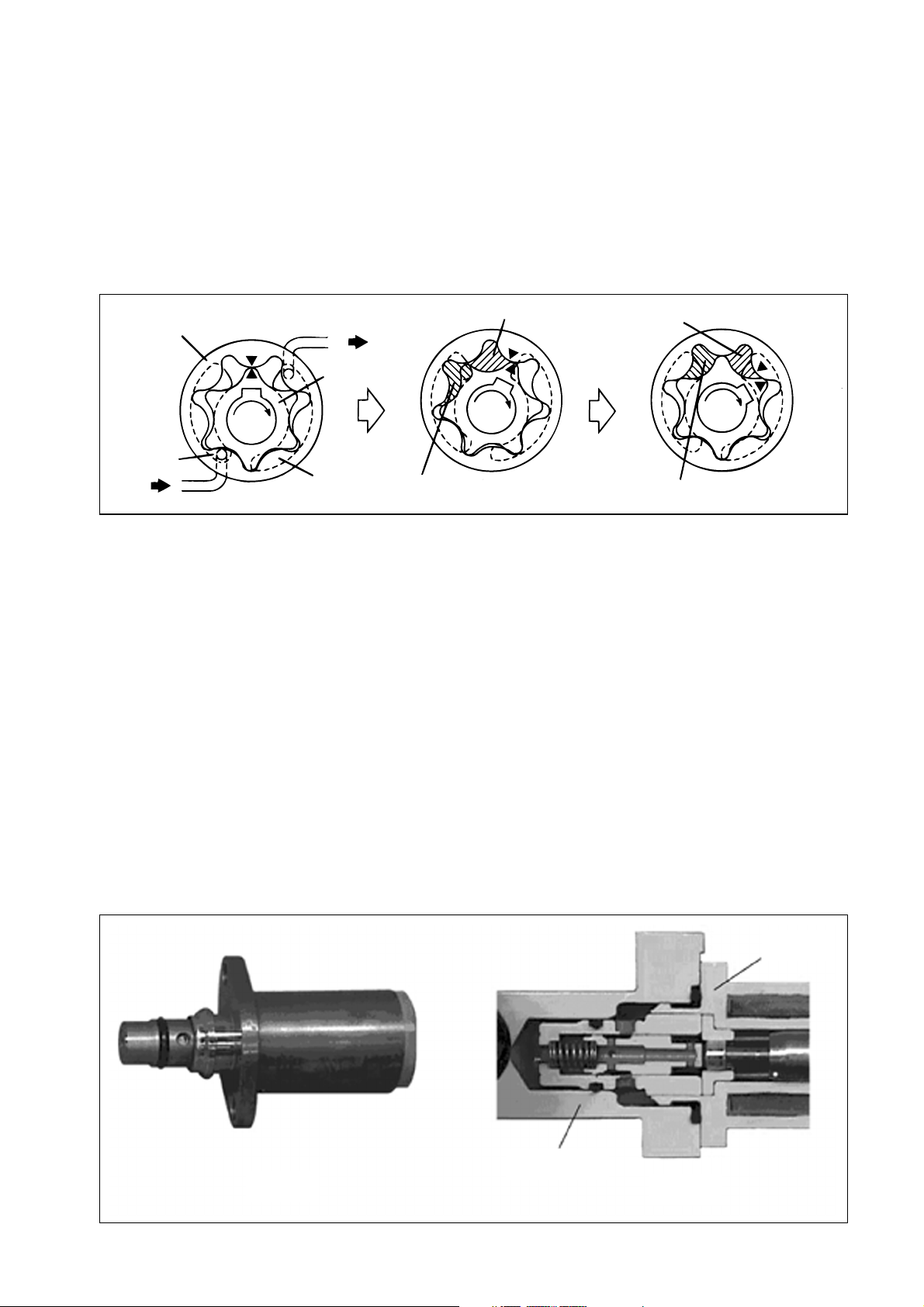
(1) Feed Pump
The trochoid type feed pump, which is integrated in the supply pump, draws fuel from the fuel
tank and feeds it to the two plungers via the fuel filter and the SCV (Suction Control Valve).
The feed pump is driven by the drive shaft. With the rotation of the inner rotor, the feed pump
draws fuel from its suction port and pumps it out through the discharge port. This is done in
accordance with the space that increases and decreases with the movement of the outer and
inner rotors.
Outer rotor
Intake port
from Fuel tank
to Pump chamber
Inner rotor
Discharge
port
Quantity decrease
Quantity increase
Quantity decrease (fuel discharge)
Quantity increase (fuel intake)
QD0708E
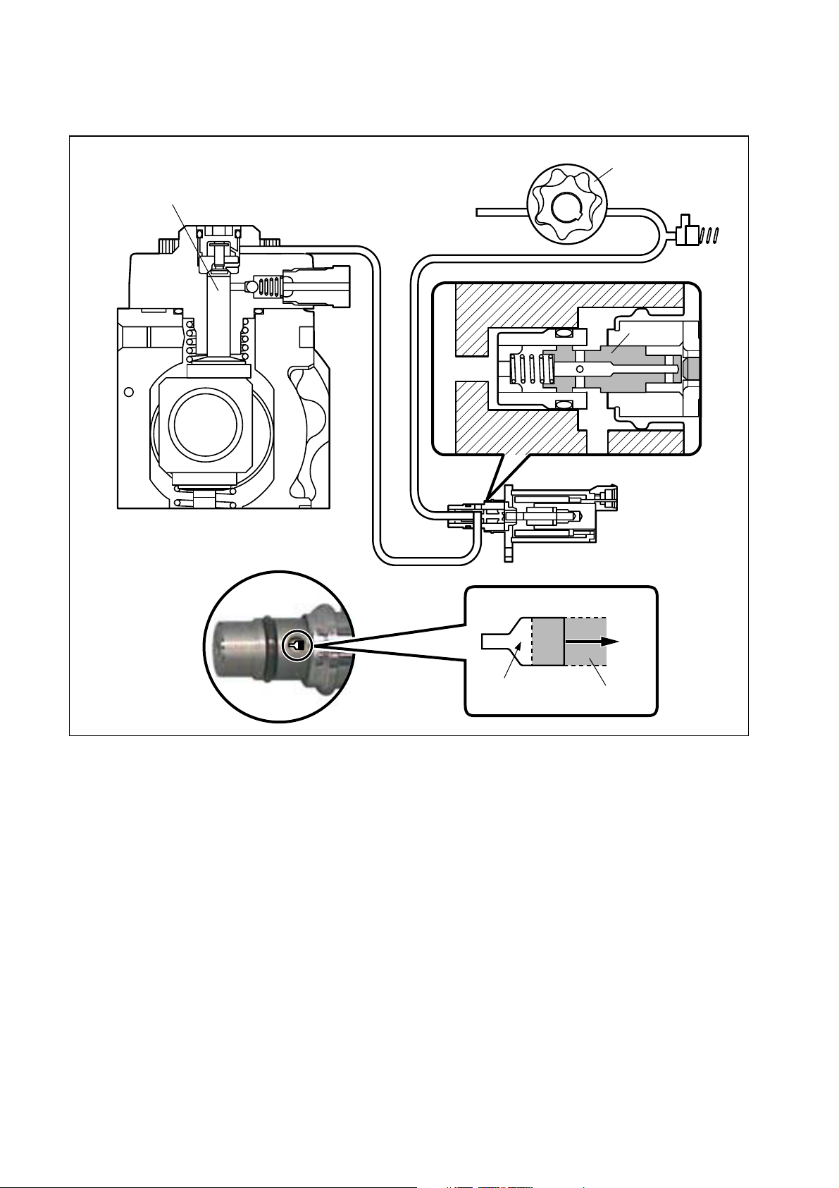
(2) SCV: Suction Control Valve
• A linear solenoid type valve has been adopted. The ECU controls the duty ratio (the length
of time that the current is applied to the SCV), in order to control the quantity of fuel that is
supplied to the high-pressure plunger.
• Because only the quantity of fuel that is required for achieving the target rail pressure is
drawn in, the drive load of the supply pump decreases.
• When current flows to the SCV, variable electromotive force is created in accordance with
the duty ratio, moving the armature to the left side. The armature moves the cylinder to the
left side, changing the opening of the fuel passage and thus regulating the fuel quantity.
• With the SCV OFF, the return spring contracts, completely opening the fuel passage and
supplying fuel to the plungers. (Full quantity intake and full quantity discharge)
• When the SCV is ON, the force of the return spring moves the cylinder to the right, closing
the fuel passage (normally opened).
• By turning the SCV ON/OFF, fuel is supplied in an amount corresponding to the actuation
duty ratio, and fuel is discharged by the plungers.
Exterior view of SCV
SCV
Pump body
Cross-section of SCV
Q000050E
11
Page 14
[In case of short duty ON]
Short duty ON → large valve opening → maximum intake quantity
Plunger
SCV
Feed pump
Cylinder
Large opening
Cylinder
Q000051E
12
Page 15

[In case of long duty ON]
Long duty ON → small valve opening → minimum intake quantity
Plunger
SCV
Feed pump
Cylinder
Small opening
Cylinder
Q000052E
13
Page 16

[3] Rail
(1) Outline
• Stores pressurized fuel (0 to 180 MPa) that has been delivered from the supply pump and
distributes the fuel to each cylinder injector. A rail pressure sensor and a pressure limiter are
adopted in the rail.
• The rail pressure sensor (Pc sensor) detects the fuel pressure in the rail and sends a signal
to the engine ECU, while the pressure limiter controls the fuel pressure in the rail.
Pressure limiter
Rail pressure (Pc) sensor
Q000147E
(2) Rail Pressure (Pc) Sensor
This sensor detects fuel pressure in the rail and sends a signal to the ECU. It is a semi-conductor type pressure sensor that utilizes the characteristic whereby electrical resistance
changes when pressure is applied to silicon.
Vcc
GND
Vout
Vcc
Pc
sensor
(supply voltage)
Vout
(output voltage)
GND (ground)
+5V
ECU
Vout [V]
4.2
1.0
0 200
Rail pressure [MPa]
Q000053E
14
Page 17

(3) Pressure Limiter
The pressure limiter relieves pressure by opening the valve if abnormally high pressure is
generated. The valve opens when pressure in rail reaches approximately 230 MPa, and
closes when pressure falls to approximately 50 MPa. Fuel leaked by the pressure limiter returns to the fuel tank.
To the fuel tank
Spring
Ball (valve)
Pc
QC0020E
15
Page 18

[4] Injector
(1) Outline
The injectors inject the high-pressure fuel from the rail into the combustion chambers at the
optimum injection timing, rate, and spray condition, in accordance with commands received
from the ECU.
(2) Characteristics
• A compact, energy-saving solenoid-control type TWV (Two-Way Valve) injector has been
adopted.
• QR codes displaying various injector characteristics are laser marked in the injector body,
and ID codes showing these in numeric form (22 alphanumeric figures) are laser marked on
the connector head.
• This system uses QR code information to optimize injection quantity control. When an injector
is newly installed in a vehicle, it is necessary to input the ID codes in the ECU.
(3) Construction
22-characters
Leak
passage
QR code
to Fuel tank
Solenoid valve
High pressure fuel
(from Rail)
Command piston
Valv e
spring
Nozzle spring
Seat area
Nozzle needle
Q000148E
16
Page 19

(4) Operation
The TWV valve opens and closes the outlet orifice to control the hydraulic pressure in the
control chamber, and the start and the end of injection.
[No injection]
• When no current is supplied to the solenoid, the valve spring force is stronger than the
hydraulic pressure in the control chamber. Thus, the TWV is pushed downward, effectively
closing the outlet orifice. For this reason, the hydraulic pressure in the control chamber is
applied to the command piston causes the nozzle spring to compress. This closes the nozzle
needle, and as a result, fuel is not injected.
[Injection]
• When the current is initially applied to the solenoid, the attraction of the solenoid pulls the
TWV up, effectively opening the outlet orifice and allowing the fuel to flow out of the control
chamber. After the fuel flows out, the hydraulic pressure in the control chamber decreases
pulling the command piston up. This causes the nozzle needle to rise and injection to start.
• The fuel that flows past the outlet orifice flows to the leak pipe and below the command
piston. The fuel that flows below the nozzle needle lifts the it upward, which helps to improve
the nozzle's opening and closing response.
• When current continues to be applied to the solenoid, the nozzle reaches its maximum lift,
where the injection rate is also at the maximum level. When current to the solenoid is turned
OFF, the TWV falls, causing the nozzle needle to close immediately and the injection to stop.
Solenoid
TWV
Outlet orifice
Inlet orifice
Command
piston
Nozzle
needle
Leak pipe
No injection
Actuation
current
Valve spring
Rail
Control chamber
pressure
Injection rate
Injection
Actuation
current
Control chamber
pressure
Injection rate
Actuation
current
Control chamber
pressure
Injection rate
End of injection
Q000149E
17
Page 20

(5) QR Code
QR (Quick Response) codes have been adopted to enhance the injection quantity precision
of the injectors. The adoption of QR codes enables injection quantity dispersion control
throughout all pressure ranges, contributing to improvement in combustion efficiency, reductions in exhaust gas emissions and so on.
QR Code Correction Point
180 MPa
140 MPa
P4-3
Injection
Quantity: Q
P4-1
P5-2
P5-1
P4-2
P3-2
P3-1
Actuating Pulse Width: Tq
90 MPa
64 MPa
P3-3
P2-1
P1-1
QR Code ( 9.9 mm)
ID Code
(22 sets of 16 alphanumeric figures)
25 MPa
18
Contents of Printing
TP
1-1 TP2-1 TP3-1
TP3-2 TP3-3 TP4-1
TP4-2 TP4-3 TP5-1
TP5-2 BCC
Q000150E
Page 21

3.2 Description of Control System Components [1] ECU (Electronic Control Unit)
This is the command center that controls the fuel injection system and engine operation in
general.
[Outline Diagram]
Sensor
Detection Calculation
Engine ECU
Actuator
Actuation
Q000152E
[2] Description of Sensors
(1) Crankshaft Position Sensor (NE sensor)
The NE sensor is an MRE (Magnetic Resistance Element) type sensor. It is positioned above
the crankshaft to detect the crankshaft position. The pulsar gear is composed of 56 gears with
4 gears missing (per 1 revolution), and the sensor outputs 56 pulses for each 1 revolution of
the crankshaft (360°CA).
Exterior Drawing
Vcc
NE-
Circuit Diagram
Vcc
NE+
NE-
ECU
Vcc
NE input circuit
NE+
Q000154E
(2) Cylinder Recognition Sensor (G sensor)
The cylinder recognition sensor (G sensor) is an MRE (Magnetic Resistance Element) type
sensor. It detects the engine cylinders, and outputs 5 pulses for every two revolutions of the
engine (720°CA).
Exterior View Diagram
Vcc
G-
G+
19
Circuit Diagram
Vcc
G+
G-
ECU
Vcc
G input circuit
Q000155E
Page 22

(3) Fuel temperature sensor (THF)
Detects the fuel temperature and sends a corresponding signal to the engine ECU. Based on
this information, the engine ECU calculates the injection volume correction that is appropriate
for the fuel temperature.
Resistance Value Characteristics
Temperature
(°C)
Thermistor
Resistance value
(kΩ)
-30 (25.4)
-20
-10 (9.16)
0 (5.74)
10 (3.70)
20
30 (1.66)
40 (1.15)
50 (0.811)
60 (0.584)
70 (0.428)
80 0.318±0.031
90 (0.240)
100 (0.1836)
110 (0.1417)
120
15.0±1.5
2.45±0.24
(0.1108)
Fuel temperature sensor
Q000156E
20
Page 23
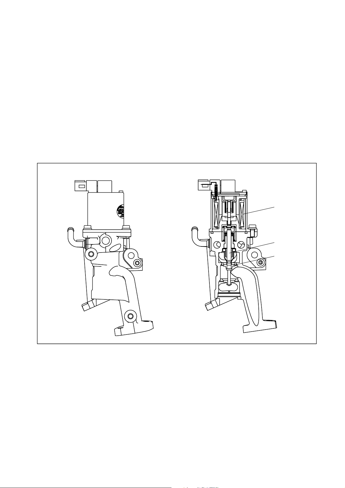
[3] EGR Valve (Exhaust Gas Recirculation Valve)
(1) EGR Valve Construction
An EGR valve is utilized as the system actuator for the electric exhaust gas recirculation (EEGR) system. It is constructed of an upper section and a lower section. The upper section
receives output signals from the engine ECU, and contains a solenoid that generates electromagnetic force. The lower section is constructed of a nozzle that moves up and down in
response to the electromagnetic force, and a valve with an opening that alters in response to
the nozzle position.
(2) EGR Valve Operation
The E-EGR system electronically controls the EGR. The EGR system reduces NOx by lowering the combustion temperature. This is done recirculating a portion of the exhaust gases
through the intake manifold. Because this system also reduces the engine output and affects
driveability, the E-EGR system effects computer control to achieve an optimal EGR volume
in accordance with the driving conditions.
Exterior View
Solenoid
Nozzle
Valve
Q000153E
21
Page 24

3.3 Various Types of Controls [1] Outline
This system effects fuel injection quantity and injection timing control more appropriately than
the mechanical governor and timer used in the conventional injection pump.The engine ECU
performs the necessary calculations in accordance with the sensors installed on the engine and
the vehicle. It then controls the timing and duration of time in which current is applied to the
injectors, in order to realize both optimal injection and injection timing.
(1) Fuel Injection Quantity Control Function
The fuel injection quantity control function replaces the conventional governor function. It
controls the fuel injection to an optimal injection quantity based on the engine speed and accelerator position signals.
(2) Fuel Injection Timing Control Function
The fuel injection timing control function replaces the conventional timer function. It controls
the injection to an optimal timing based on the engine speed and the injection quantity.
(3) Fuel Injection Rate Control Function
Pilot injection control injects a small amount of fuel before the main injection.
(4) Fuel Injection Pressure Control Function (Rail Pressure Control Function)
The fuel injection pressure control function (rail pressure control function) controls the discharge volume of the pump by measuring the fuel pressure at the rail pressure sensor and
feeding it back to the ECU. It effects pressure feedback control so that the discharge volume
matches the optimal (command) value set in accordance with the engine speed and the injection quantity.
22
Page 25
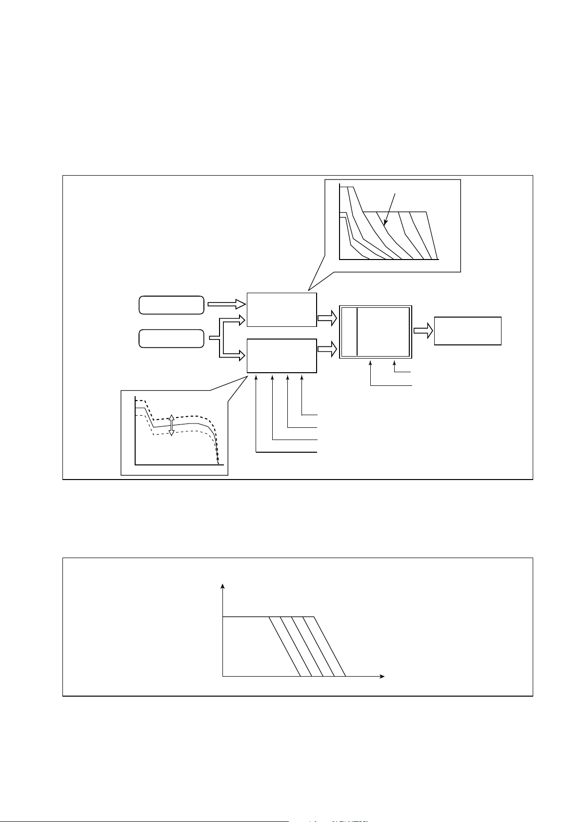
[2] Fuel Injection Quantity Control
(1) Outline
This control determines the fuel injection quantity by adding coolant temperature, fuel temperature, intake air temperature, and mass airflow corrections to the basic injection quantity
is calculated by the engine ECU, based on the engine operating conditions and driving conditions.
(2) Injection Quantity Calculation Method
The basic injection quantity is obtained through the governor pattern
calculated from the accelerator position and the engine speed.
The basic injection quantity is then compared to the maximum
injection quantity obtained from the engine speed, to which various
types of corrections are made. The smallest injection quantity is then
used as the basis for the final injection quantity.
Accelerator position
Engine speed
Injection quantity
Engine speed
Basic injection
quantity
Maximum injection
quantity
Mass airflow correction
Intake air temperature correction
Atmospheric pressure correction
Cold operation maximum injection quantity correction
Accelerator position
Injection quantity
Engine speed
Final injection
quantity after
correction
Smaller quantity
Driver actuation
timing calculation
Individual cylinder correction
Injection pressure correction
Q000061E
(3) Basic Injection Quantity
The basic injection quantity is determined by the engine speed (NE) and the accelerator position. The injection quantity is increased when the accelerator position signal is increased
while the engine speed remains constant.
Basic injection quantity
Accelerator position
Engine speed
QC0038E
23
Page 26

(4) Maximum Injection Quantity
The maximum injection quantity is calculated by adding the mass airflow correction, intake
air temperature correction, atmospheric pressure correction and the cold operation maximum injection quantity correction to the basic maximum injection quantity that is determined
by the engine speed.
Basic maximum injection quantity
Engine speed
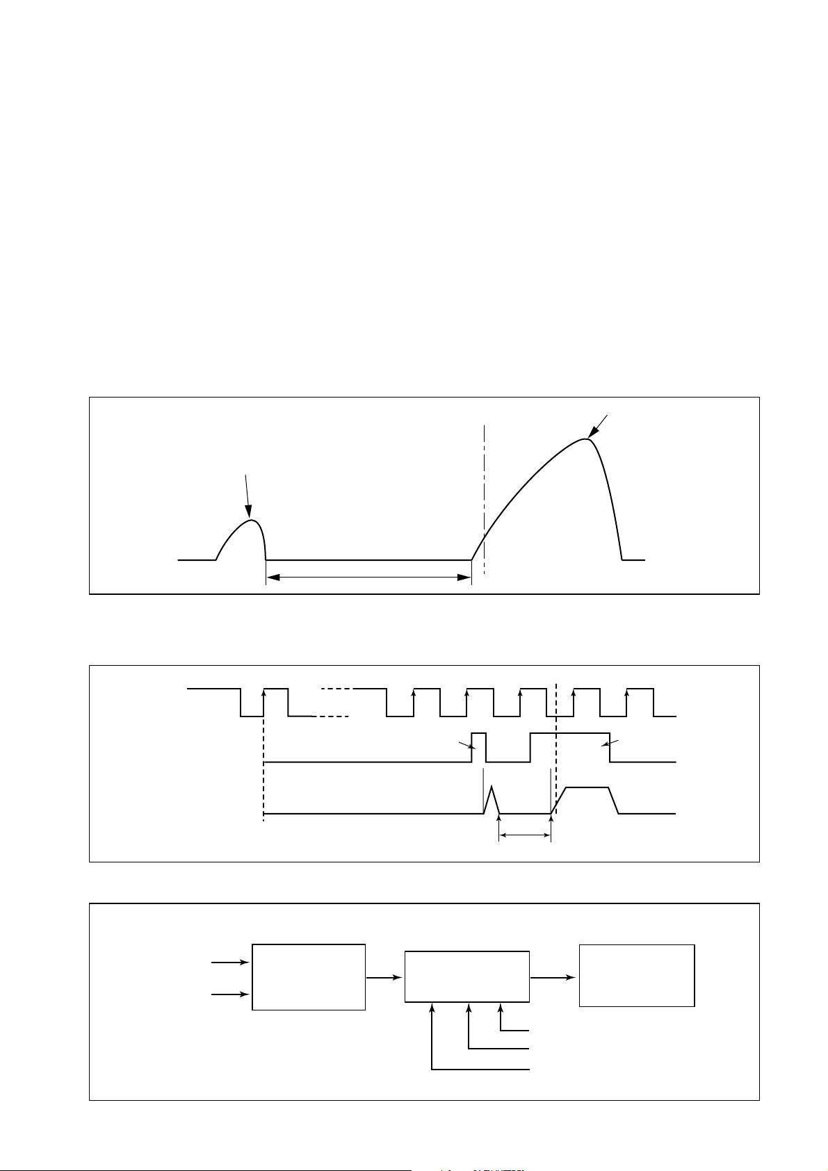
(5) Starting Injection Quantity
When the starter switch is turned ON, the injection quantity is calculated in accordance with
the starting base injection quantity and the starter ON time. The base injection quantity and
the inclination of the quantity increase/decrease change in accordance with the coolant temperature and the engine speed.
QC0039E
Injection quantity
Base injection
quantity
STA ON duration
STA/ON
Injection quantity
Starting
Coolant temperature
High
STA ON duration
STA/ON
Low
Starting
(6) Idle Speed Control (ISC) System
This system controls the idle speed by regulating the injection quantity in order to match the
actual speed to the target speed that is calculated by the engine ECU.
The target speed varies according to the type of transmission (manual or automatic), whether
the air conditioner is ON or OFF, the shift position, and the coolant water temperature.
(7) Idle Vibration Reduction Control
To reduce engine vibrations during idle, this function compares the angle speeds (times) of
the cylinders and regulates the injection quantity for the individual cylinders if there is a large
the difference, in order to achieve a smooth engine operation.
QC0040E
Angle
speed
#1 #1 #3 #4 #2#3 #4 #2
Crankshaft angle
Correction
Crankshaft angle
QC0043E
24
Page 27
[3] Fuel Injection Timing Control
(1) Outline
Fuel injection timing is controlled by varying the timing in which current is applied to the injectors.
(2) Main and Pilot Injection Timing Control
[Main Injection Timing]
The engine ECU calculates the basic injection timing based on the engine speed the final
injection quantity, and adds various types of corrections in order to determine the optimal
main injection timing.
[Pilot Injection Timing (Pilot Interval)]
Pilot injection timing is controlled by adding a pilot interval to the main injection timing. The
pilot interval is calculated based on the final injection quantity, engine speed, coolant temperature (map correction). The pilot interval at the time the engine is started is calculated
from the coolant temperature and speed.
Pilot injection
Interval
(3) Injection Timing Calculation Method
[Outline of Control Timing]
01
NE pulse
Solenoid valve
control pulse
Nozzle needle lift
Top deadcenter
Pilot injection
Pilot
injection
timing
Main injection
QC0044E
Actual TDC
Main injection
Main
injection
timing
[Injection Timing Calculation Method]
Engine speed
Injection quantity
Basic injection
timing
25
Corrections
Pilot interval
Main injection
timing
Intake air temperature correction
Coolant temperature correction
Atmospheric pressure correction
QD0382E
Q000062E
Page 28
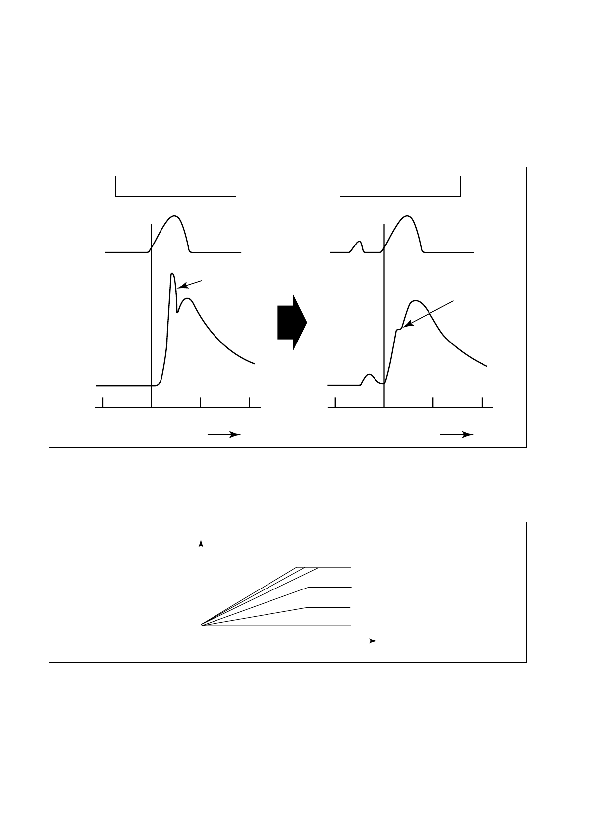
[4] Fuel Injection Rate Control
While the injection rate increases with the adoption of high-pressure fuel injection, the ignition
lag, which is the delay from the start of injection to the beginning of combustion, cannot be
shortened to less than a certain value. As a result, the quantity of fuel that is injected until main
ignition occurs increases, resulting in an explosive combustion at the time of main ignition. This
increases both NOx and noise. For this reason, pilot injection is provided to minimize the initial
injection rate, prevent the explosive first-stage combustion, and reduce noise and NOx.
Pilot Injection
Small first-stage
combustion
Crankshaft angle (deg)
QC0046E
Injection
rate
Heat release
rate
-20 TDC 20 40
Normal Injection
Large first-stage
combustion
(NOx and noise)
-20 TDC 20 40
Crankshaft angle (deg)
[5] Fuel Injection Pressure Control
A value that is determined by the final injection quantity, the water temperature and the engine
speed is calculated. During the starting of the engine, the calculation is based on the water temperature and the atmospheric pressure.
Rail pressure
Final injection quantity
Engine speed
[6] Other Controls
a: Limit maximum injection quantity b: Gradual acceleration injection quantity
c: Gradual deceleration injection quantity d: Post-acceleration damping injection quantity
e: Reference injection quantity f: Fuel cutoff
g: Turbo control h: Glow plug relay
i: EGR control
26
QC0047E
Page 29

4. External Wiring Diagram
4.1 ECU External Wiring Diagram
Injector
Injector
Shield wire
CRANK
Shield wire
Fuel temp.
Boost pressure 1
Twist pair
CLY1
CLY4
CLY3
CLY2
Twist pair
CAM
Atmospheric
pressure
Coolant temp.
(COMMON1)
(COMMON2)
(NE-VCC)
(SH-GND)
(PATM-VCC)
(PATM-GND)
(THW-GND)
(THF-GND)
(PIM-VCC)
(PIM-GND)
(LOIL-SW)
Low oil level switch
(TWV1)
(TWV3)
(TWV2)
(TWV4)
(G+)
(G-)
(G-VCC)
(NE+)
(NE-)
(PATM)
(THW)
(THF)
(PIM1)
(Engine side)
E55:12V-REF
E52:O-PL-INVV1
E50:O-PL-INVV3
E51:12V-REF
E56:O-PL-INVV2
E53:O-PL-INVV4
E54
E49
E40:I-F-CAM
E3:S-R-5VRTN
E28:S-S-5VREF
(Vehicle Side)
V56:P-S-PROTBATT
V52:P-S-PROTBATT
V39:I-SL-STARTER
Electronic control unit
E27:CRANK
E15:S-R-5VREF
E39:S-S-5VREF
E16:GSFGND
V44:S-S-5VREF
V32:S-R-5VRTN
E18:S-S-5VREF
E31:I-AH-BAROT
E6:S-R-5VRTN
E17:S-R-5VRTN
E30:I-AH-CLT
E5:S-R-5VRTN
E43:I-AH-FUELT
E9:S-S-5VREF
E44:I-A-BOOSTP
E22:S-R-5VRTN
E25:I-SH-LOWOIL
V43:S-S-5VREF
V31:S-R-5VRTN
V41:S-S-5VREF
V29:S-R-5VRTN
V42:S-S-5VREF
V30:S-R-5VRTN
V16:I-SL-BRAKE2
V40:I-SL-GEARPOSN
V3: I-SL-BRAKE1
V50:BATT
V25:O-SL-MPR
V13:P-S-IGN
V37:P-S-IGN
V49:GSFGND
V53:GSFGND
V51:HSGGND
V55:HSGGND
V15:I-F-VSS
V7:I-A-PPS1
V6:I-A-PPS2
V19:I-A-MAT
V17:I-A-MAF
V5:I-A-A/C
(BATT)
(+B)
(+B)
(M-REL)
(IG-SW)
(IG-SW)
(STA-SW)
Starter switch
(GND)
(GND)
(P-GND)
(P-GND)
(SPD)
(ACCP1-VCC)
(ACCP1)
(ACCP1-GND)
(ACCP2-VCC)
(ACCP2)
(ACCP2-GND)
(THA)
(MAF-VCC)
(MAF)
(MAF-GND)
(PAC-VCC)
(PAC)
(PAC-GND)
(BK2-SW)
(CL-SW)
(BK1-SW)
Vehicle speed
sensor
Pedal
position
sensor 1
Pedal
position
sensor 2
Air mass flow
AC pressure
Brake switch 2 (N.C)
Clutch switch (N.C)
Main relay
Key switch
D
to IG
Brake switch 1 (N.O)
27
Q000158E
Page 30
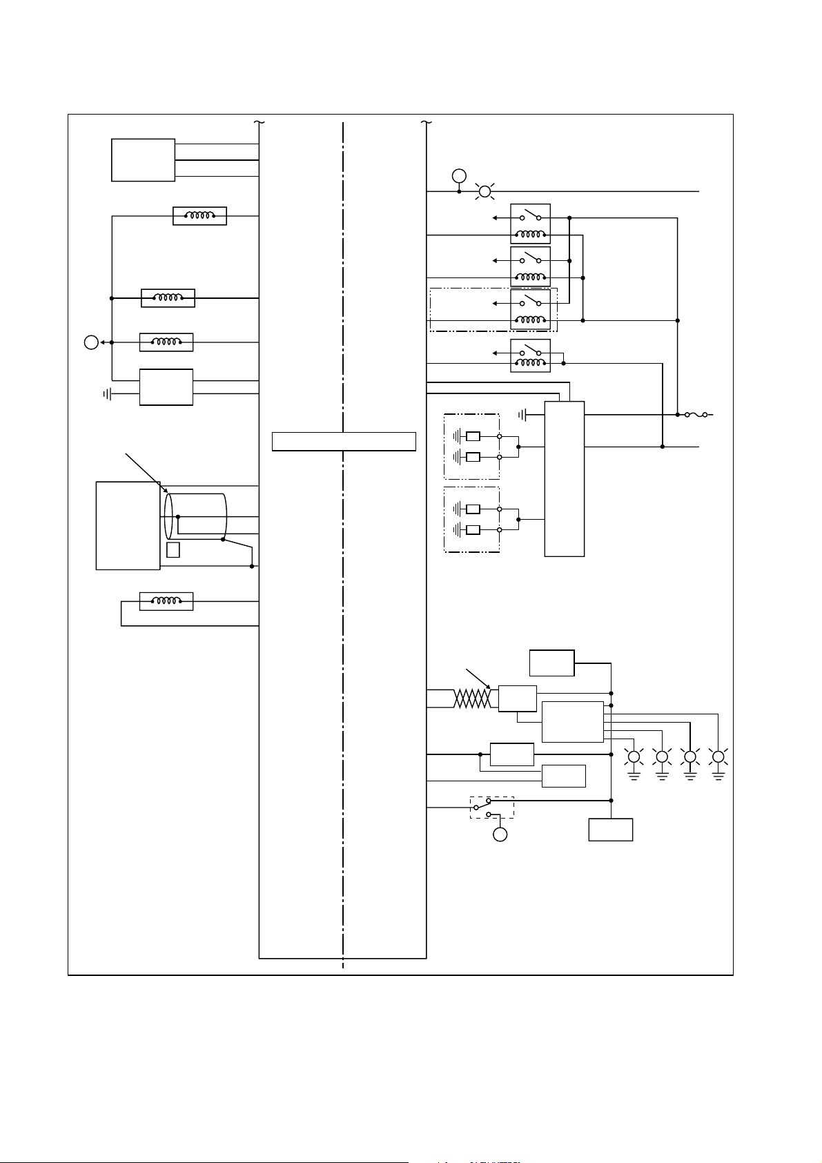
(Joint to)
D
EGR position
VSS solenoid
Turbo solenoid
Inatake valve
controller
(LEGR-VCC)
(LEGR-GND)
EGR solenoid
(LEGR)
(EGR)
(VSS)
(VNT)
(I/T-ST)
(I/T)
E19:S-S-5VREF
E45:I-A-EGRP
E7:S-R-5VRTN
E48:O-PL-EGR
E12:O-PL-VSS
E35:O-PL-Turbo
E38:I-PL-I/T
E23:O-PL-I/T
V24:O-SL-DIAGLAMP
V23:O-SL-FAN1
V35:O-SL-FAN2
V47:O-SL-FAN3
V48:O-SL-ACCRLY
V11:O-SL-GLOWRLY
V27:I-SL-GLOWDIAG
A
(MIL)
Fan control relay 1
(FAN1-REL)
Fan control relay 2
(FAN2-REL)
Fan control relay 3
(FAN3-REL)
Available only with AC
A/C cut off relay
(ACT-REL)
(GL-ST)
(GLOW-DI)
MIL
to IG
+B
E
BATT (+)
Shield wire
Rail pressure
High pressure pump solenoid
(PFUEL-VCC)
(PFUEL)
(PFUEL)
(PFUEL-GND)
(SCV+)
(SCV-)
Electronic control unit
E8:S-S-5VREF
E21:I-A-RAILPS
E33:I-A-RAILPS
E20:S-R-5VRTN
E11:12V-REF
E24:O-PL-PRESSURE
V21:C-CANHI
V33:C-CANLO
V14:O-PL-TN
V1:O-PL-FC
V2:S-DATA1
Twist pair
(CAN-H)
(CAN-L)
(NEOUT)
(FUELOUT)
(ISO-K)
Immobilizer
to IG
Glow
controller
ABS/TC
BCM
IP-cluster
Glow
EPS
MID
A
K-line
SAE1962
Oil level
LED
SVS
Oil press.
warning
28
Q000159E
Page 31

4.2 ECU Connector Diagram [1] ECU Connector Terminal Layout
Vehicle Side (V)
V12V11V10V9 V8V7V6 V5V4 V3V2V1 V50V49
V24 V23 V22 V21 V20 V19 V18 V 17 V16 V1 5 V1 4 V13 V52 V51
V36V35 V34V33 V32V31 V30V29 V28V27 V26V25 V54V53
V48 V47 V46 V45 V44 V43 V42 V 41 V40 V3 9 V3 8 V37 V56 V 55
Engine Side (E)
E12E11E10E9 E8E7E6 E5E4 E3E2E1 E50E49
E24 E23 E22 E21 E20 E19 E18 E 17 E16 E1 5 E1 4 E13 E52 E 51
E36E35 E34E33 E32E31 E30E29 E28E27 E26E25 E54E53
E48 E47 E46 E45 E44 E43 E42 E 41 E40 E3 9 E3 8 E37 E56 E 5
[2] Terminal Connections
(1) Vehicle Side (V)
Wire
Cross-section
(proposal)
0.75mm
0.75mm
0.75mm
0.75mm
0.75mm
0.75mm
0.75mm
0.75mm
0.75mm
0.75mm
0.75mm
0.75mm
0.75mm
0.75mm
0.75mm
0.75mm
0.75mm
0.75mm
0.75mm
2
2
2
2
2
2
2
2
2
2
2
2
2
2
2
2
2
2
2
Pin
Pin Name
(ISUZU)
Pin Name
(DENSO)
V29 S-R-5VRTN MAF-GND
V30 S-R-5VRTN PAC-GND
V31 S-R-5VRTN ACCP2-GND
V33 C-CANLO CAN-L
V34
V3 5 O-SL-FAN2 FAN2-RE L
V39 I-SL-STARTER STA-SW
I-SL-GEARPOSN
V40
CL-SW
V41 S-S-5VREF MAF-VCC
V42 S-S-5VREF PAC-VCC
V43 S-S-5VREF ACCP2-VCC
V44 S-S-5VREF ACCP1-VCC
V45
V4 7 O-SL-FAN3 FAN3-RE L
V49 GSFGND GND
V51 HSGGND P-GND
P-S-PROTBATT
V52
+B
V53 GSFGND GND
V55 HSGGND P-GND
P-S-PROTBATT
+B
Pin
Pin Name
(ISUZU)
Pin Name
(DENSO)
V1 O-PL-FC FUELOUT
V2 S-DATA1 ISO-K
V3 I-SL-BRAKE1 BK1-SW
V4 V32 S-R-5VRTN ACCP1-GND
V5 I-A-A/C PAC
V6 I-A-PPS2 ACCP2
V7 I-A-PPS1 ACCP1
V8 V36
V9 V37 P-S-IGN IG-SW
V10 V38
O-SL-GLOWRLY
V11
O-SL-WTGLOW1
V12
GL-ST
HEAT1-REL
V13 P-S-IGN IG-SW
V14 O-PL-TN NEOUT
V15 I-F-VSS SPD
V16 I-SL-BRAKE2 BK2-SW
V17 I-A-MAF MAF
V18 V46
V19 I-A-MAT THA
V20 V48 O-SL-ACCRLY ACT-REL
V21 C-CANHI CAN-H
V22 V50 BATT BATT
V2 3 O-SL-FAN1 FAN1-REL
O-SL-DIAGLAMP
V24
MIL
V25 O-SL-MPR M-REL
V26 V54
I-SL-GLOWDIAG
V27
GLOW-DI
V28 V56
5
Q000160E
Wire
Cross-section
(proposal)
0.75mm
0.75mm
0.75mm
0.75mm
0.75mm
0.75mm
0.75mm
0.75mm
0.75mm
0.75mm
0.75mm
0.75mm
0.75mm
0.75mm
0.75mm
1.5mm
1.5mm
1.5mm
1.5mm
1.5mm
1.5mm
1.5mm
2
2
2
2
2
2
2
2
2
2
2
2
2
2
2
2
2
2
2
2
2
2
29
Page 32

(2) Engine Side (E)
Wire
Cross-section
(proposal)
Pin
Pin Name
(ISUZU)
Pin Name
(DENSO)
Pin
Pin Name
(ISUZU)
Pin Name
(DENSO)
E1 E29
E2 E30 I-AH-CLT THW 0.75mm2
2
E3 S-R-12VRTN G-
0.75mm
E31 I-AH-BAROT PATM 0.75mm2
E4 E32
2
E5 S-R-5VRTN THF-GND
E6 S-R-5VRTN PATM-GND
E7 S-R-5VRTN LEGR-GND
E8 S-S-5VREF PFUEL-VCC
E9 S-S-5VREF PIM-VCC
0.75mm
0.75mm
0.75mm
0.75mm
0.75mm
E33 I-A-RAILPS PFUEL 0.75mm2
2
E34
2
E35 O-PL-Turbo VNT 0.75mm2
2
E36
2
E37
E10 E38 I-PL-I/T I/T-ST
E11 12V-REF SCV+
E12 O-PL-VSS VSS
0.75mm
0.75mm
2
E39 S-S-5VREF NE-VCC
2
E40 I-F-CAM G+
E13 E41
E14 E42
2
E15 I-F-CRANK Lo NE-
E16 GSFGND SH-GND
E17 S-R-5VRTN THW-GND
E18 S-S-5VREF PATM-VCC
E19 S-S-5VREF LEGR-VCC
E20 S-R-5VRTN PFUEL-GND
E21 I-A-RAILPS PFUEL
E22 S-R-5VRTN PIM-GND
E23 O-PL-I/T I/T
O-PL-PRESSURE
E24
SCV-
E25 I-SH-LOWOIL LOIL-SW
0.75mm
0.75mm
0.75mm
0.75mm
0.75mm
0.75mm
0.75mm
0.75mm
0.75mm
0.75mm
0.75mm
E43 I-AH-FUELT THF
2
E44 I-A-BOOSTP PIM1
2
E45 I-A-EGRP LEGR
2
E46
2
E47
2
E48 O-PL-EGR EGR
2
E49
2
E50 O-PL-INVV3 TWV3
2
E51 12V-REF COMMON2
2
E52 O-PL-INVV1 TWV1
2
E53 O-PL-INVV4 TWV4
E26 E54
2
E27 I-F-CRANK Hi NE+
E28 S-S-5VREF G-VCC
0.75mm
0.75mm
E55 12V-REF COMMON1
2
E56 O-PL-INVV2 TWV2
Wire
Cross-section
(proposal)
0.75mm
0.75mm
0.75mm
0.75mm
0.75mm
0.75mm
0.75mm
1.5mm
1.5mm
1.5mm
1.5mm
1.5mm
1.5mm
2
2
2
2
2
2
2
2
2
2
2
2
2
30
 Loading...