

Page 1
SUPPLEMENT
ISUZU
MOTORS
LIMITED
':
Page 2
*
g
G
-CAMERON
&
SONS
PTY.
BOX
116
P.O.
oRANGE
2800
rrl
ISUZU
WORKSHOP
MANUAL
DIESEL ENGINE
C223 TURBO MODEL
SUPPLEMENT
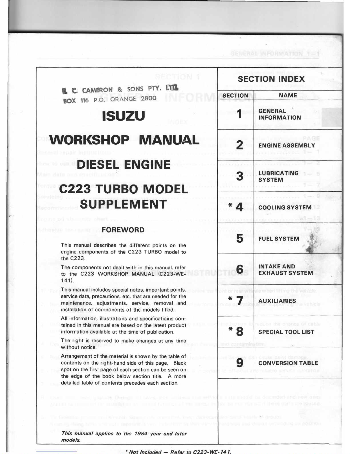
FOREWORD
This
manual
describes the
different
points
on the
engine components
of the
C223 TURBO
model to
the c223.
The
components not
dealt
with in
this
manual, refer
to the
C223 WORKSHOP
MANUAL
rc223-WE-
141l,.
This
manual includes
special notes,
important
points,
service data,
precautions,
etc.
that are needed
for
the
maintenance,
adjustments,
service,
removal
and
installation
of components of the models titled.
All
information,
illustrations
and
specificatioins
con-
tained in this manual
are
based on
the latest
product
information
available
at the time of
publication.
The right
is
reserved
to
make changes at any time
without
notice.
Arrangement
of
the material is
shown by the table of
contents
on the
right-hand
side of this
page.
Black
spot on the first
page
of each
section can be seen
on
the edge of the
book below
section title.
A
more
detailed
table of
contents
precedes
each section.
This
manual applies
models.
1984
year
and later
SECTION
INDEX
SECTION
NAME
1
GENERAL
INFORMATION
2
ENGINE ASSEMBLY
3
LUBRICATING
SYSTEM
*4
COOLING
SYSTEM
5
FUEL SYSTEM
s
-.\$
si
ir
6
INTAKE AND
EXHAUST SYSTEM
*7
AUXILIARIES
*8
SPECIAL
TOOL LIST
I
CONVERSION
TABLE
included
Refer to C223-WE-141.
Page 3
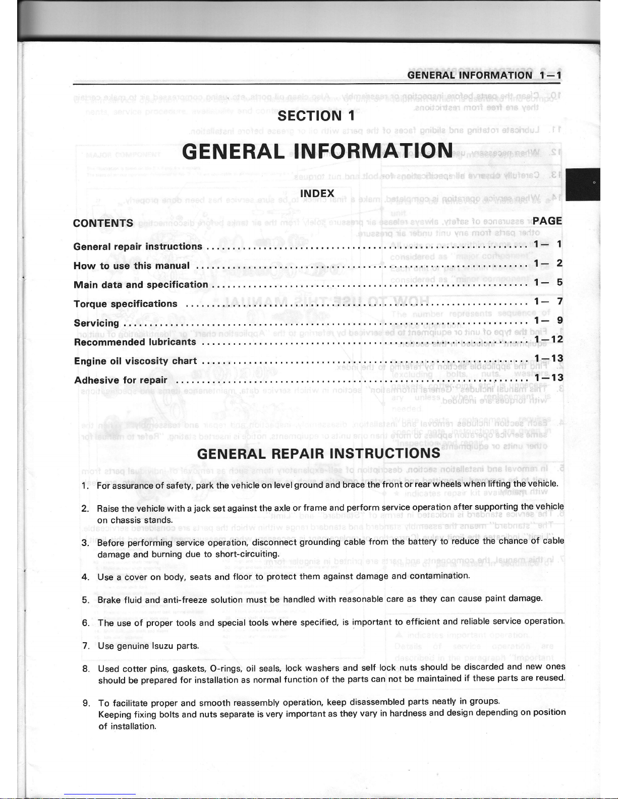
GENERAL
INFORMATION
1_1
sEcTloN
1
GENERAL
INFORMATION
INDEX
CoNTENTS
PAGE
Generat
repairinstructions....
....1-
1
How to use this
manual
. . . .
1-
2
Maindataandspecification
.......1-
5
Torquespecifications
..'.'.
1- 7
Servicing
'.....1-
I
Recommended
lubricants
..
.
1-12
Engineoil viscositychart
...1-13
Adhesive for repair
GENERAL
REPAIR
INSTRUCTIONS
1. For
assurance
of safety,
park
the
vehicle on level
ground
and
brace the
front
or
rear wheels
when lifting
the
vehicle.
2. Raise
the
vehicle
with
a
jack
set against
the axle
or frame
and
perform
service
operation
after supporting
the
vehicle
on chassis stands.
3.
Before
performing
service
operation, disconnect
grounding
cable
from the
battery
to
reduce
the chance
of
cable
damage
and
burning due
to
short-circuiting.
4.
Use a cover on body, seats
and
floor to
protect
them against
damage
and
contamination.
5.
Brake
fluid and anti-freeze solution
must be
handled
with
reasonable care as
they
can cause
paint
damage'
6.
The
use of
proper
tools
and special tools
where specified,
is
important to efficient
and
reliable service
operation.
7. Use
genuine
lsuzu
parts.
8. Used
cotter
pins, gaskets,
O-rings, oil seals,
lock
washers and self
lock nuts should
be discarded
and
new
ones
should be
prepared
for installation as
normal
function
of the
parts
can not be
maintained
if
these
parts
are
reused.
9. To facilitate
proper
and smooth
reassembly
operation.
keep
disassembled
parts
neatly
in
groups.
Keeping fixing bolts and
nuts separate
is
very important as
they
vary in hardness
and
design
depending
on
position
of
installation.
Page 4
1
-2
GENERAL
INFORMATION
10.
Clean the
parts
before
inspection or
reassembly. Also
clean oil
ports,
etc. using compressed
air
to make
certain
they
are free
from restrictions.
1 1. Lubricate rotating and sliding
faces
of the
parts
with oil or
grease
before
installation.
12. When
necessary,
use
a sealer
on
gaskets
to
prevent
leakage.
13.
Carefully observe
all specifications
for
bolt and
nut
torques.
14, When
service
operation is completed, make a
final check to be sure service
has
been done
properly.
15. For
assurance of
safety,
always
release
air
pressure
solely
from
the air
tanks before disconnecting
pipes,
hoses or
other
parts
from
any unit under air
pressure.
HOW TO
USE
THIS MANUAL
Find
the
Wpe
of unit or
equipment to
be
serviced by
referring
to the
"Application
chart" or
"ldentification
of unit or
equipment"
included
in this
section.
Find
the
applicable
section by
refering
to the
index.
This
manual includes
"General
information" section
in which
service data,
maintenance
items and
specifications
with
torques are
included.
Each
section
includes
removal
and
installation, disassembly,
inspection and
repair
and
reassembly.
When
the
same service
operation applies to more than one un;ts
or equipments.
notice is inserted stating,
"Refer
to manual
for
other units
or equipments".
ln removal
and
installation
section. description
of self-explanatory
items such as
removal of individual
parts
from
unit to be
removed, is omitted
and
important operation
such as
adjustments,
torque specifications,
etc. are
dealt
with
mainly.
6.
The
service standard
is indicated in terms
of
"Standard"
and
"Limit".
The
"standard"
means the assembly
standard
and standard
range within which the
parts
are considered
serviceable.
"Limit"
indicates the limit
value
(Correction
or
replacement
is necessary
when
measurement
is beyond this
limit.)
7.
ln
this
manual, the components and
parts
are
printed
in
singular
form.
1.
,4'
2.
3.
4.
5.
Page 5
GENERAL
INFORMATION
1-3
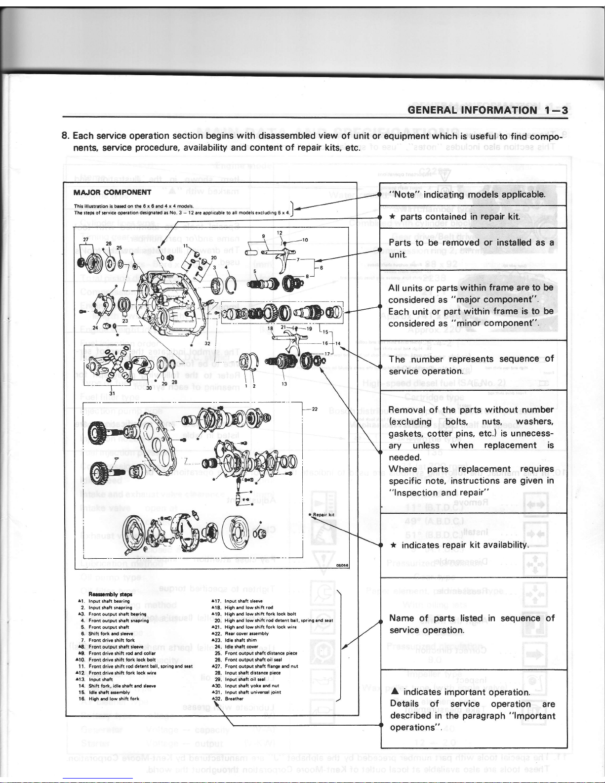
8.
Each
service operation
section begins
with
disassembled
view
of unit
or equipment which
is useful
to find
compo-
nents, service
procedure,
availability and content of
repair
kits,
etc.
MA'OR COMPONENT
Thi, illurtration b b.!.d on th. 6
r
6 and
4 r 4 modolr.
Tha ltaF of srvice otsralaon
d..iFat d as
No.
3 - 12
are eppliQble
to sll
modclr
€rcluding
6
x 4
2A
I I rt25
$@bu,
-"-}a.^
-----:l
--l_"
Rmfi5ly
tt
p.
al.
lnpd 3hafr b..ring
2. lnput thalt $afine
13.
Front
output 3h.lt baaring
4. Front
output ah.lt
3nrpring
5.
Front
outpt rhaft
6. Shitt
lork
.nd rld.
7.
Front
driva
lhifr
tork
.8.
F.@t
output rhaft,l6va
49.
Front
driv.
.hitt rod .nd coll.r
ll0.
Front
driy. ,hift
to.k l@k bolt
I l.
Front
drir.
rhilt
rod d.t.nt
blll,
rpring lnd
nai
^12.
Front
d.ivc.hift to.k ldk
wi..
^13.
lnput
rhaft
14. Shitt
iort, idl..hrft
.nd dcvc
15. ldl. th.tt.smbly
16. Hish.nd low.hittlork
^17.
lnput rh.tt rl.rv!
^18.
Hieh
md low shift
rod
.19.
High.nd
low thih fo.k lmk bolt
m.
High .d ld.hift
rod d.r6nt b.ll, ipri.0.nd cat
421.
High
ard
low thift
lork ldk
wit€
422,
nrar covar arsmbly
^23.
ldl..h.tl thim
24.
ldla th.ft @vd
25.
Front output lhalt dirt.ne
pi.6
26.
Front outpul rh.lt oil $d
^27.
Front
output lhatt
llanga.nd nut
28.
lnput shah
di.t.n6
pi.c.
29.
lnput rhatt oil sal
aA).
lnpd.h.lt
yok.
and
nut
^31.
lnpul
fialt
univ.rsl
ioint
8..athar
__l
"Note"
indicating
models applicable.
*
parts
contained in
repair kit.
Parts
to
be
removed
or installed as a
unit.
All
units or
parts
within frame are to be
considered
as
"major
component".
Each
unit
or
part
within frame
is to
be
considered
as
"minor
component".
The
number
represents sequence
of
service
operation.
Removal
of the
parts
without
number
(excluding
bolts,
nuts,
washers,
gaskets,
cotter
pins,
etc.) is unnecess-
ary
unless
when replacement is
needed.
Where
parts
replacement
requires
specific
note, instructions
are
given
in
"lnspection
and
repair"
*
indicates
repair kit
availability.
Name
of
parts
listed in
sequence
of
service operation.
A
indicates
important
operation.
Details
of service operation
are
described in the
paragraph
"lmportant
operations".
Page 6
1-4
GENERAL INFORMATION
V
@
lmportant operrtions
l lnFlrh6ftb€rring
-
3.
Front
outpul
ftrft b.rring
lnstaller. 9.8522.0O4O.0
_r\
__r-t\_____r_.\
8.
F?ont
dtpul !h.lt tlolvr
17.
lnput
rheft
rloor.
The
shitt lork
groove
side taces downward.
I
rdr
-
oool
H'9h
6.d
low
rh't ro.
1r@nr
d
ooj
L
Front
dra !h,lt
rcd
L-
"i-l
9.
F.ontdrivcrhih
rod.rd coll.r
18. High.rd low
rhifl
rod
The
pans
rnclude
thift
rodr
lor
high
and
low
tpeed relection and
for
Direction ot
inilallarion
of the
pans
thould b€ carefullv nored.
To,que
ltg
ml
4
5 5
Fronl driv. ihilt
lork lock bolt
High
lrd
low
shiti
lork lock bll
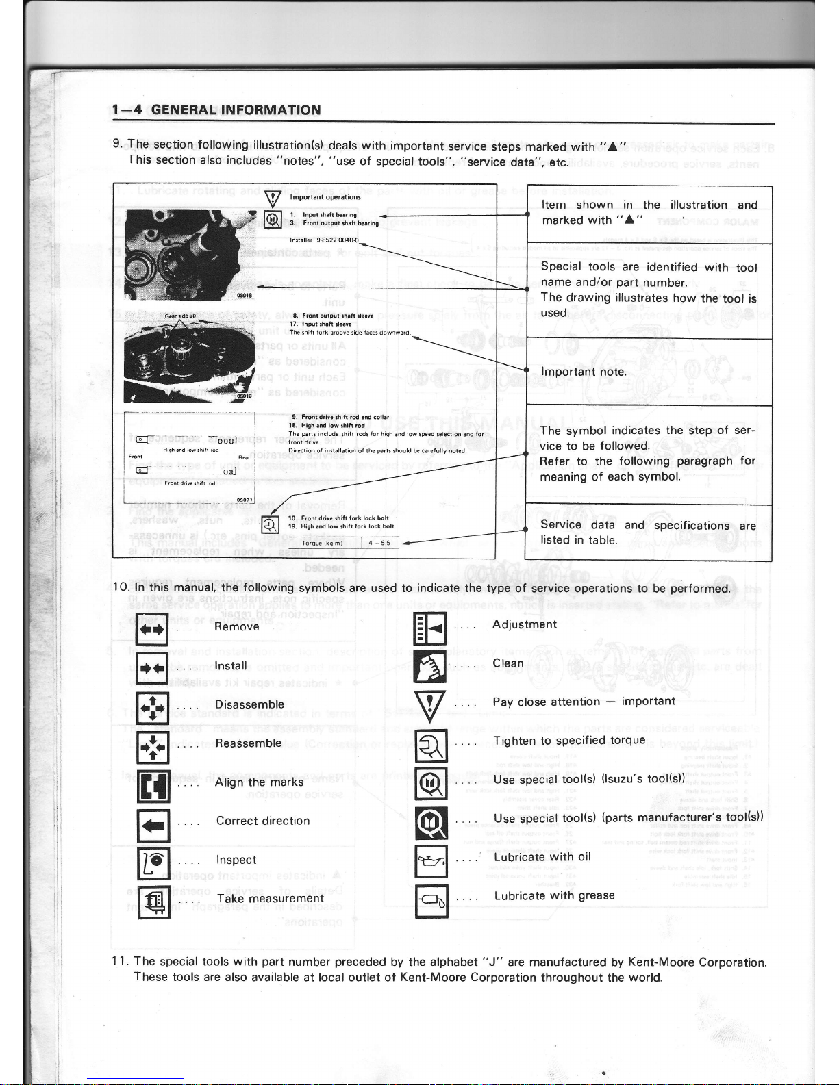
Item
shown in the illustration
and
marked
with
"4"
Special
tools
are identified
with
tool
name
and/or
part
number.
The
drawing illustrates
how
the
tool is
used.
lmportant
note.
The
symbol
indicates the step
of ser-
vice to be
followed.
Refer to the
following
paragraph
for
meaning of each symbol.
Service
data
and
specif ications
are
listed
in table.
9. The
section following
illustration(s)
deals
with
important
service
steps marked with
"A"
This
section
also includes
"notes".
"use
of
special tools",
"service
data", etc.
10.
ln
this manual.
the
following
symbols are used to
indicate
the type
of
service
operations to
be
performed.
tr
E
E
E
H
E
tr
@
. Remove
.
lnstall
.
Disassemble
Reassemble
Align
the
marks
Correct
direction
lnspect
Take measurement
Adjustment
Clean
Pay
close
attention
-
imPortant
Tighten to specified
torque
Use
special
tool(s)
(lsuzu's
tool(s))
Use
special
tool(s)
(parts
manufacturer's
tool(s))
Lubricate
with oil
Lubricate
with
grease
ffi
6
V
q
@
@[
tr
tr
11.
The
special tools with
part
number
preceded
by the
alphabet
"J"
are manufactured
by
Kent-Moore
Corporation.
These
tools are also
available at local outlet of
Kent-Moore Corporation
throughout the
world.
Page 7
GENERAL INFORMATION 1
-5
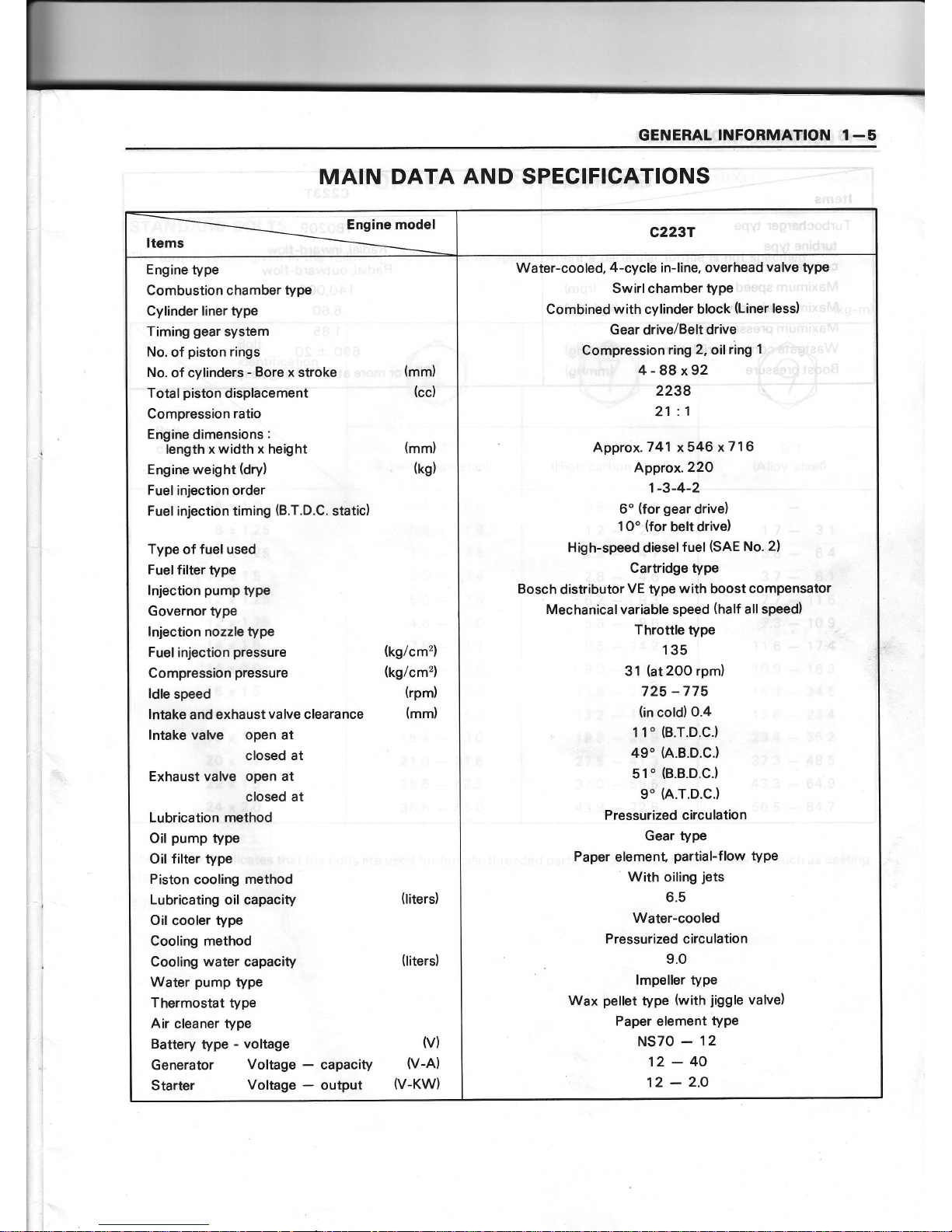
MAIN DATA AND SPECIFICATIONS
Engine model
Items
c2237
Engine
type
Combustion chamber type
Cylinder liner type
Timing
gear
system
No.
of
piston
rings
No.
of cylinders
-
Bore
x
stroke
(mm)
Total
piston
displacement
(cc)
Compression
ratio
Engine
dimensions
:
lengthxwidthxheight
Engine weight
(dry)
Fuel
injection order
Fuel injection timing
(B.T.D.C.
static)
Type of fuel used
Fuelfilter
type
lnjection
pump
type
Governor type
lnjection nozzle type
Fuel
injection
pressure
Compression
pressure
ldle
speed
lntake
and
exhaust
valve
clearance
lntake valve open at
closed at
Exhaust valve open at
closed at
Lubrication
method
Oil
pump
type
Oil filter type
Piston
cooling
method
Lubricating oil capacity
Oil
cooler
type
Cooling method
Cooling water capacity
Water
pump
type
Thermostat
type
Air
cleaner
type
Battery
type
- voltage
Generator
Voltage
Starter
Voltage
(titers)
(liters)
capacity
output
v)
v-A)
V.KW)
(mm)
(kg)
(tg/cm')
(kg/cm'z)
(rpm)
(mm)
Water-cooled,
4-cycle
in-line,
overhead
valve
type
Swirl chamber
type
Combined
with
cylinder block
(Liner
less)
Gear
drive/Belt
drive
Compression
ring2,oil
ring
1
4-88x92
2238
21
:1
Approx.
741
x546 x7'l
6
A,pprox.22O
1-3-4-2
6o
(for
gear
drive)
1O"
(for
belt drive)
High-speed
dieselfuel
(SAE
No.
2)
Cartridge type
Bosch
distributor
VE
type
with
boost
compensator
Mechanicalvariable
speed
(half
all speed)
Throttle type
135
31
(at
2OO
rpm)
725
-775
(in
cold)
0.4
1 1"
(B.T.D.C.)
49'(A.B.D.C.)
51'
(B.B.D.C.)
9"
h.T.D.C.)
Pressurized circulation
Gear
tYPe
Paper
element
partial-flow
tYPe
With
oiling
jets
6.5
Water-cooled
Pressurized
circulation
9.O
lmpeller tyPe
Wax
pellet
type
(with
jiggle
valve)
Paper
element
tYPe
NS70
-
12
12-40
12
-
2.O
Page 8
I€
ENEfiAT.'
I
NFO
RMATION
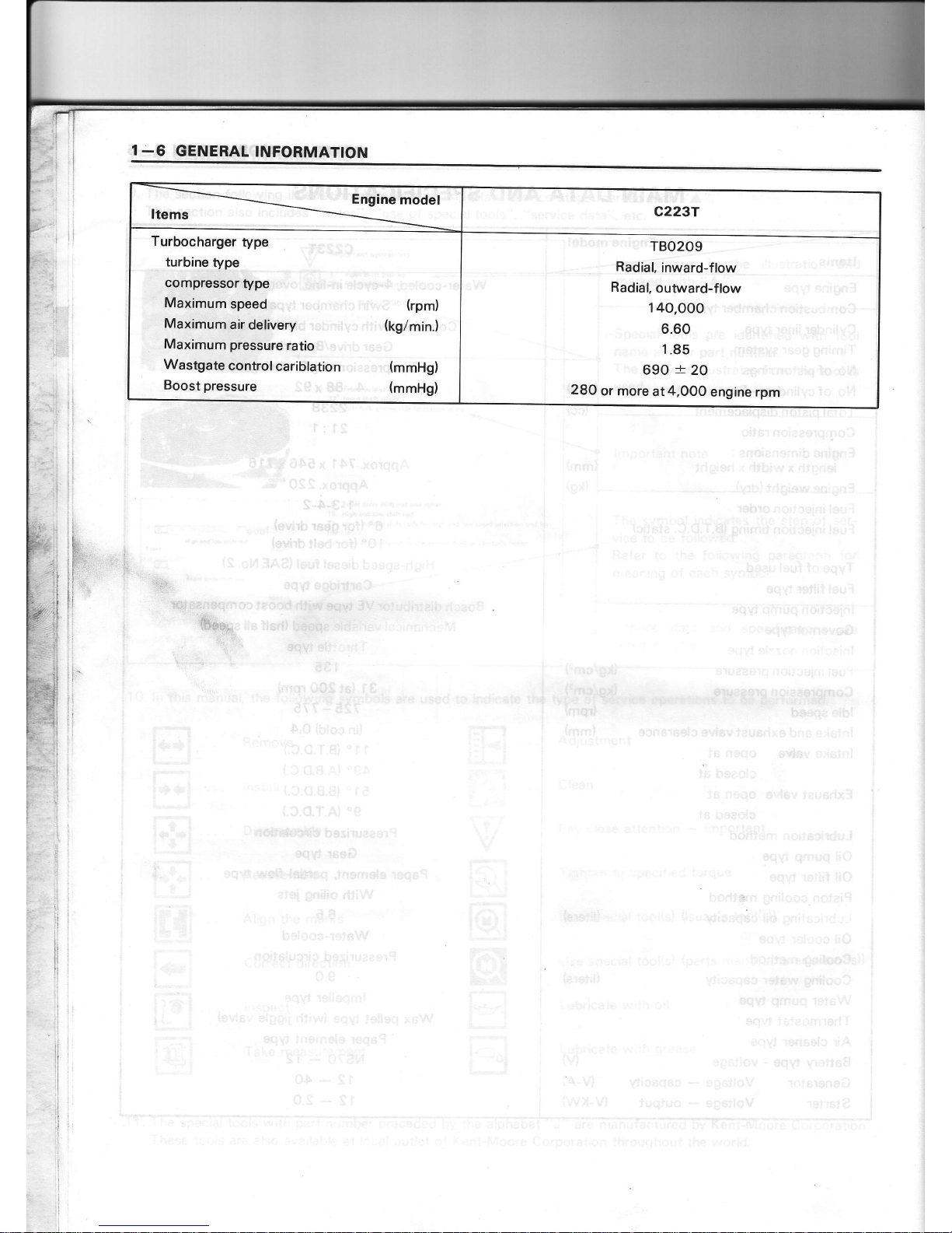
Engine
model
Items
c2237
Turbocharger
type
turbine
type
compressor
type
Maximumspeed", (rpm)
Maximumair
delivery
(kg/min.)
Maximum pressure
ratio
Wastgate
controlcariblation
(mmHg)
Boost
pressure
(mmHg)
TBO209
Radial,
inward-flow
Radial,
outward-flow
140.OOO
6.60
1.85
690
:t
20
28O
or more
at4,OO0
engine rpm
Page 9
:,iGEff'EftAftel
mqmffim@fl
.€t-{7
TOROU E
SPEGIFICATIO
NS'
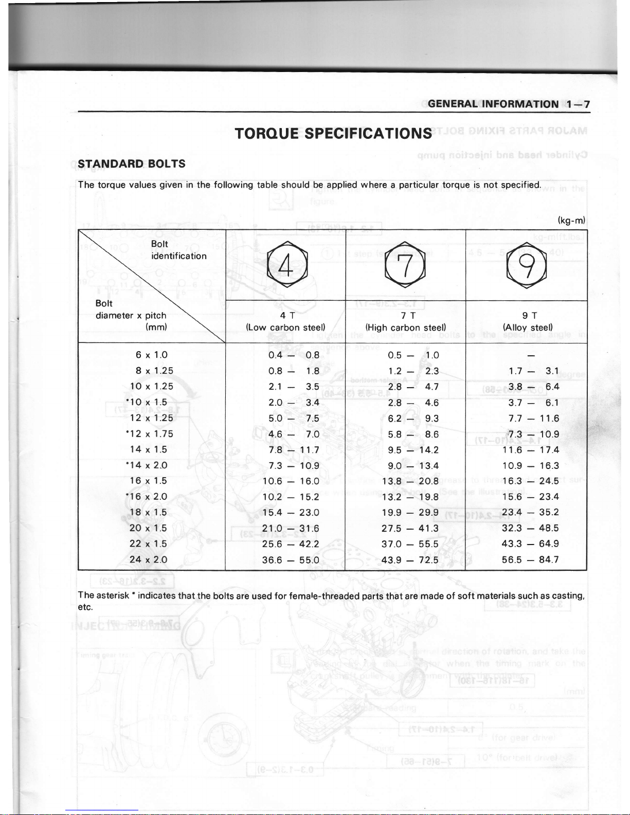
STAilIDARD
BOLTS
:ihe
tor{ue
values
given
in the
foliowing table shouid be
bpplied
where
a
particu-lar
tbrque is n-oi
ipecified.
1
ri
I, i:
-S.3
,
The
asterisk' indicates
that the
bolts
arb used
for female-thieadgd
part6'thbt
are
made of soft
materials
such as
casting,
:
etc.
, r\.{.
"",:,:ri
il
t'a_:
-il
(kg-m);
Bolt
identif ication
Bolt
diameter
x
pitch
(mm)
4T
"
(Low
carbon steel)
l,
7T
(High
carbon
steel)
9T
(Alloy
steel)
6 x
1.O
8 x
1.25
10
x
1.25
'1O
x 1.5
-
r't
'12
x
1.fr
'12 x
1.75
14
x
1.5
'14 x
2.O
16
x
1.5
116
x 2.0
\8'x 1.5
Q\,r"
\O
x--1.5
22\ 1.s
:
24.
io
0.4 - o.8
0.8
-
1.8.
2.1
-
3.5
2.O
-
3.A
$.Q
-
./,9
,
:.1,6
-
7.0
7.8
-
11.7
7.3
-
10.9
10.6
-
16.0
10.2
-
15.2
f5.4
-
23.0
,!1-O_1;31;6
25.6
:42.2
36.6
-
55
0.5
-
.:1.0
1.2
-'t'r.g-
':1,'
:"
l
2.8
-
4.7
2.8
-
4.6
6.2
-
9.3
5.8
;
8.6
9.5'-.
1'4.2
9.0
,-
13.4
13.8 - 20.8
13.2
:
19.8
19.9
-
29.9 ;i*
!
t'l
27.5
-
41.5*-
.
37.0-55.5j.J
:i
43.9
-
72.5
'z
1.7
-
3.1
r.*.
.r'3,.8
-
6.4
.J
3.7
-
6.1
7.7
-
11.6
,fl.3 : Jo.e
-
-:
!+tr-<'*
t
11
.6
-
17.4
10.9
-
16.3
r
6.3
-
24.5
15.6
-
23.4
,i"
""-
J,3.4
-
35.2
E
_j+-"F'.$,t
32.3
-
48.5
'
,'
43.3
-
64.9
.
56.5
-
84.7
;:il
-#
{t#
Page 10

1
-8
GENERAL
INFORMATION
MAJOR
PARTS
FIXING
BOLTS
Cylinder
head
and
injection
pump
(kg-m)
----4
Y
ffi1-@
1.3-1.8(1F13)
1.8-2.411T171
2.2-3.2116-231
-"'t:
?C
__-tr.:---
':'.O----H,
16-18(116-130)
Page 11
GENERAL INFORMATION
1
_9
'i€ffi3:434':):
-ffi-rio=a
ffi
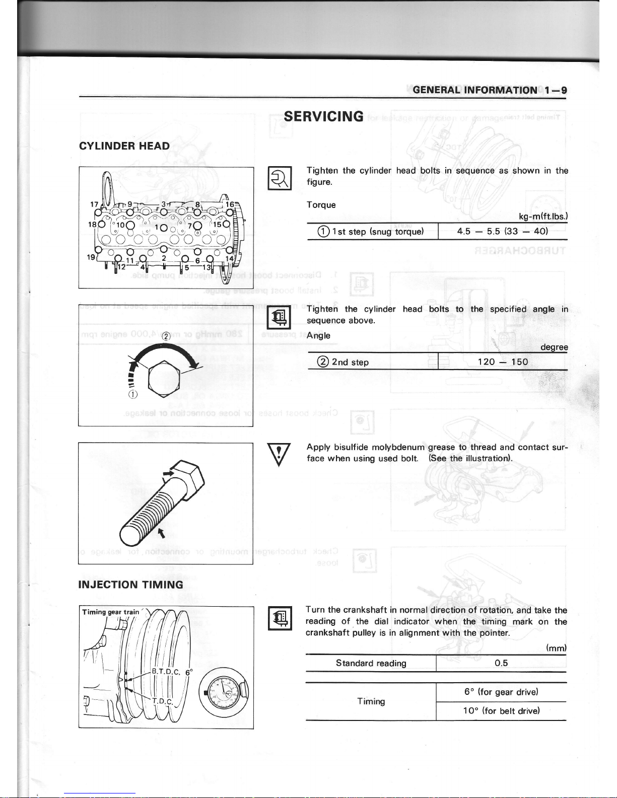
CYLINDER
HEAD
INJECTION
TIMING
SERVICING
Tighten
the
cylinder head bolts
in
sequence as shown
in
the
f igure.
Torque
Tighten
the
cylinder
head
bolts
to the
specified angle
in
sequence above.
Angle
Apply
bisulfide molybdenum
grease
to thread
and contact sur-
face when
using used bolt.
(See
the
illustrationl.
Turn
the crankshaft in
normal
direction of
rotation,
and take
the
reading
of the
dial
indicator when
the timing mark on
the
crankshaft
pulley
is in
alignment
with
the
pointer.
(mm)
0.5
@
t
st step
(snug
torque)
I
I
(t
6o
(for
gear
drive)
1Oo
(for
belt drive)
Standard reading
Page 12

1
-1O
GENERAL
INFORMATION
Timing
belt
train
TURBOCHARGER
Disconnect
boost hose at
injection
pump
side.
lnstall
boost
pressure gauge.
Take
measurement with
specified
engine
speed
at
no load.
1.
2.
3.
Check
boost
hoses
for
loose connection
or
leakage.
Check
turbocharger mounting
or connection for leakage
or
loose.
Page 13

GENERAL INFORMATION 1
-11
Check oil line
for leakage
restriction or damage.
Page 14

1
-12
GENERAL INFORMATION
RECOM
MENDED LUBRICANTS
h
: : lil
, ! il
j
1i1.
ii,
.
:.1
il
'Jl
.11
;ir
il'
t- i: ..*
irt
:i;'
LUBRICANT
Engine
Engine
cooling
system
MAKE AND BRAND
CD
grade
*
BESCO S-3 ENGINE OIL
BP VANELLUS C3
BP VANELLUS
C3
MULTIGRADE
CHEVRON
DELO
4OO
MOTOR
OIL
CHEVRON
DELO 3OO MOTOR
OIL
CASTROL
or
DEUSOL
CRD
CASTROL or
DEUSOL CRF
CASTROL
or
DEUSOL
RX
SUPER
CALTEX RPM
DELO
4OO
OIL
CALTEX
RPM DELO 3OO
OIL
ESSOLUBE D-3
ENIAGIP
F.1 DIESEL
SIGMA
MOBIL DELVAC
12OO
SERIES
MOBIL DELVAC
13OO
SERIES
MOBIL DELVAC SUPER
MOBIL
DELVAC
SHC
SHELL
RIMULA CT OIL
SHELL
RIMULA
X
OIL
SHELL
MYRINA OIL
SUNFLEET
SUPER C
SUNFLEET
DIESELUBE
SUNFLEET
DIESELUBE
XD
TEXACO URSA
OIL
SUPER
TEXACO URSA OIL
LA-3
TOTAL RUBIA
S
TOTAL RUBIA
TM
UNION GUARDOL
MOTOR
OIL
*
ISUZU
ANTI-FREEZE PT
BP ANTIFROST
CALTEX
AF
COOLANT
CASTROL
ANTI-FREEZE
CHEVRON
ATLAS PERMA-GUARD
ANTI-FREEZE
AND
COOLANT
ENI AGIP
F.1 ANTI-FREEZE
ESSO RAD
MOBIL PERMAZONE
SHELLZONE
SHELL GLYCOSHELL
PLUS
SHELLSAFE
TEXACO
ANTI-FREEZE
COOLANT
TEXACO STARTEX
ANTI-FREEZE
COOLANT
TOTAL
ANTIGEL
UNION
YEAR AROUND
ANTI-FREEZE AND
COOLANT
*
Mark ... lsuzu
genuine
lubricants
Diesel
engine oil
CD
grade
Permanent
type anti-
freeze solution
Page 15

ENGINE
OIL VISCOSITY
GRADE
-
AMBIENT TEMPERATURE
Ambient
'l
-30'C
TemperatureJ(
-20oF
)
(80"F)
{90"F
sAE 10W-40
sAE
1
5W-40,1 5W-50,20W-40,20W-50
ENGINE
OIL
VISCOSITY
CHART
ADHESIVE
FOR REPAIR
MAKE
ISUZU
Genuine
parts
or
Recommended
Brand
name or
Number
Remarks
Loctite
Loctite 242
(Loctite
Nutlock)
Loctite 262
(Loctite
Studlock)
Loctite
290
(Loctie
A.A.)
Loctite Primer N
rL-242
rL-262
TL-290
Locquic
primer
grade
N
Three Bond
Belco Bond
No.
4
Belco Bond No. 5
Belco
Bond 2Ol
Three Cement
Super Three
Cement
Sealock
No. 1OO0
TB-1
1
04
TB-1
1
05
TB-1
102
TB-1
521
-B
TB,1 741
T8-2302
Seal
End
Seal
End
No. 22S
Seal
End No.242
.TB-1102
(Three
Bond)
'TB-1104
(Three
Bond)
'
mark
means that
the
product
is
equivalent to
Three
Bond
make
or
Loc-
tite make.
Diabond
DB Bond Black
Sealer
DB Bond Yellow
Sealer
DB Bond
Clean
Sealer
.TB-1521C
ffhree
Bond)
.TB-1521
(Three
Bond)
Herme Seal
rHerme
Seal
No.
1 237
*Three
Bond 200
(Three
Bond)
Shinetsu
Kagaku
rKE41
RTV
-Super
Three
Bond No. 2O
ffhree
Bond)
'silicone
Form-A-Gasket No. 6
(Loctite)
Page 16

ENGINE ASSEMBLY 2_1
SECTION
2
ENGINE
ASSEMBLY
INDEX
:::::::"1,,.,.n
::;
I
lnspection and
repair
. .
2-2
GENERAL
DESCRIPTION
Page 17

2-2 ENGINE ASSEMBLY
INSPECTION
AND REPAIR
Piston
pin
Visually
inspect
for
damage,
wear
or other
abnormal conditions.
Outside
diameter
Measure
ference.
at several
points
Fitting
interference
between
piston pin
and
piston pin
hole.
Piston
Clearance
between
piston
ring
and
ring
grove
Standard
Limit
1st
compression ring
o.120
-
o.155
o.185
2nd
compression
ring 0.050
-
0.085 o.1 15
Oilring 0.030
-
0.070 0.100
Piston ring
Remove
deposit of carbon
from
piston
rings and check
for wear
and damage.
lnsert
the
piston
ring into
bore and
push
it in,
at a
right angle
to
the
wall,
deep
enough to
reach
the
point
where
the cylinder bore
diameter
is
smallest
then measure
the
ring
gap.
Piston ring
gap:
tr
@
(mm)
Standard
Limit
29.0 28.97
(mm)
114(4.2188in.)
o
o
C
3
.2
1st, 2nd
compression
-
o.4
Page 18

ENGINE
ASSEMBLY
2-3
,in;c5s5;l:mq
gJry-%:g
16,
Cylinder
head
assembly
Tighten
the cylinder
head
bolts
in
sequence
as
shown
in
the
figure.
Torque
Tighten
the
cylinder
head bolts to
the specified
angle in
sequence
above.
Angle
Apply
bisulfide
molybdenum
grease
to thread
and
contact
sur-
face when
using
used bolt.
(See
the
illustatiod.
Page 19

TUBRICATING
SYSTEM 3-1
sEcTloN
3
LUBRICATING
SYSTEM
INDEX
CONTENTS
PAGE
General
description
... 3-1
GENERAL DESCRIPTION
fl
=::
Oil
pres3ure
switch
Oil
filter
and
cooler assembly
I
Fitter
canridqe
llr-r r-
Valve
opening
pressure
3.5k9/cm2
Oil
pan
Page 20

sEcrloN
5
FUEL
SYSTEM
INDEX
PAGE
General
description
.
.. 5-1
lnjectionpumpdata.
.-5-2
GENERAL
DESCRIPTION
Page 21

5-2
FUEL
SYSTEM
INJECTION
VOLUME
TEST
CONDITIONS
lnjection
nozzle
I
njection
nozzle holder
I
njection
starting
pressure
lnjection
line
Transfer
pump
pressure
Test
diesel fuel
Testing
oil
temperature
ldentification
number
IDENTIFICATIONS
PLATE
AND NUMBER
MAKER%
ASS'Y N0.
INJ.PUMP
ASS'Y
N0.
8941 32
-
3580
PUMP
DATA
D.K.K.C.
P.No. 1 O5 78O-0000
Bosch
type
No.DN'l 2SD12T
D.K.K.C.
P.No. 1
O5
780-2080
Bosch
type No.EF8S1 1/9A
l5Okg/cm2
lnner
dia.
2mm
x Outer
dia.
6mm
-
Length
84Omm
O.2kg/cmz
lso
standard test oil
(lso
41 1
3)
sAE
standard test oil
(sAE
967.d)
45
-
50'C
1047 40-1
030. 1 04740-1050,
(8941
7 1
-85 1 0, 8941 7 1
-85201
1
047
40
-
1
020, 1 047 40-1 1
20, 1 047 40-1 1
30,
1
047 40
-1
1 40
INJECTION
ADJUSTMENT
i
t
E
p
I
I
'
r'
I
?
When
adjusting injection volume,
the injection
pump
identification
use
the correct
data following
number.
Page 22

FUEL SYSTEM
5-3
INJECTION
VOLUME
AND
GOVERNOR PERFORMANCE
DIAGRAM
ldentification
number: 1O474O-1O3O,
104740-151O,
(894171-851O,894171-a5.20l
Test
diesel fuel
:
SAE standard
test
diesel
fuel SAE
J967d
(or
ISO 41 13)
1.
Settings
Pump
Speed
(rpm)
Settings
Charge-air
press
(mmHg)
Difference
in
delivery
(cc)
1.1
Timing
device travel 1250 2.7
-3.1
mm o
1.2
Supply
pump pressure
1250 4.6-5.0
kg/cm2 o
Full
load
delivery
without
charge-air
pressure
ccl1
0O0st
Full-load
deliver
with
charge-air
pressure
1250
45.4-46.5
ccll0O0st
590-610 4.O
1.4
ldle
speed
regulation
375 9.3
-
1 3.3
ccl1
OOOst
0
2.O
1.5
Start
100
Min. 60
ccl1000st
o
1.6 Full-load
speed
regulation
2550 1 9.9-25.9
ccll
OOOst 590-610 7.O
1.7
Load Timer
Adjustment
ccl1 OOOst
1.8
ccl1
OOOst
2. Test
Specifications
2.1
Timing
device
2.2
Supply
pump
Overflow
delivery
2.3
Fuel
deliveries
Speed control lever
End
stop
Switch-off
ldle
stop
Partial
load
250
1.6-2.2
1
000
40.8-84.2
Fuel
delivery
ccl1
OOOsts
Charge-air
press.
(mmHg)
2150
6.4-7.O
3. Dimensions
Desig-
|
for
assembly
and
nation
I
adjustment
(mm)
3.2
-
3.4
5.7
-
5.9
1.5
-
1,7
3.4-3.6
21
-
27
deg.
9.2-11.0 mm
37
-
47
deg.
12-15
mm
deg.
mm
1250
2.6-3.2
1250
4.6-5.0
1 700
5.0-6.0
2000
6.1-6.7
21
50
7.9-8.6
Pump
Speed
(rpm)
N:rpm
ccl1 0s
2800
2550
2175
2000
1250
1250
1 150
900
600
Max.
7.O
19.4-26.4
34.8-40.4
37.1
-42.1
44.9-46.9
32.3-37.3
44.8-49.8
40.4-42.4
31.4-36.4
9.3- 13.3
Max. 3.0
max. cut-in voltage
:
8V
test
voltage : 1
2V
-14V
2.4
Solenoid
Page 23

Pump
speed
(rpml
850
1250
Pump
speed
{rpml
Page 24

FUEL SYSTEM 5-5
INJECTION VOLUME AND
GOVERNOR
PERFORMANCE DIAGRAM
ldentification
number
: 1O474O-1O21,1O474O-112O, 104740-1130,
1O474O-1140
Test
diesel
fuel
:
SAE standard
test diesel
fuel SAE J967d
(or
ISO 41131
1.
Settings
Pump
Speed
(rpm)
Settings
Charge-air
press
(mmHg)
Difference
in
delivery
(cc)
1.1
Timing
device travel
1250
3.5-3.9
mm
o
1.2
Supply
pump
pressure
1250 4.6
-
5.0
kg/cm2
o
Full
load delivery
without
charge-air
pressure
ccl1 OOOst
Full-load
deliver
with
charge-air
pressure
1250 47.8-48.8 ccll OOOst
590-610
4.O
1.4
ldle
speed
regulation
375 9.3
-
1
3.3 ccll O00st
0
2.O
1
.5 Start
100 Min. 60
ccllOOOst
o
1.6 Full-load
speed
regulation 2550
1 9.9-25.9
ccll
OOOst 590-610
7.O
1.7
CSD
Adjustment 500- 700 Cancel
speed ccllOOOst
1.8
ccl1
OOOst
2. Test Specifications
2.1
Timing
device
2.2
Supply
pump
Overflow delivery
2.3 Fuel
deliveries
Speed
control
lever
End
stop
Switch-off
ldle
stop
CSD
Adjustment
Partial
load
2.4 Solenoid
1250
3.4-4.O
250
1.6-2.2
1 000
40.8-84.2
Fuel
delivery
ccl1
OOOsts
1 700 2150
5.8-6.8
8.7
-9.4
1250
2000
4.6-5.0
6.1-6.7
Charge-air
press.
(mmHg)
Pump
Speed
(rpm)
3. Dimensions
Desig-
|
for
assembly and
nation
I
adjustment
(mm)
3.2
-
3.4
5.7
-
5.9
1.5
-
1.7
3.4-3.6
21
-
27
deg.
9.2-11.0
mm
37
-
47
deg.
12-15
mm
deg.
mm
Observations:
Upon
canceling
of
C.S.D.
check the
revolution and
make sure
no fuel
leakage
from the overflow of
C.S.D.
N:rpm
ccl1
Os
Max.
7.O
19.4-26.4
36.7
-41.7
38.4-43.4
47.3-45.3
34.1-39.1
46.5-51.5
42.7
-44.7
34.1-39.1
2800
2550
2175
2000
1250
1250
1 150
900
600
9.3-
1
3.3
Max.3.O
2.3-2.7mm
Cancel
speed
max. cut-in
voltage
:
8V
test voltage
: 1 2V
-14V
Test Oil
:
SAE J967d or
ISO 41
13
E
Page 25

Pump
speed
(rpm)
TIMING
DEVICE DIAGRAM
Page 26

INTAI(E
AND
EXHAUST
SYSTEM
6-1
sEciloN
6
INTAKE
AND
EXHAUST
SYSTEM
INDEX
CONTENTS
General
description
PAGE
lntake
and exhaust
system
6-3
Turbocharger
.
6_3
Exhaust
pipe
;
front
.
......
6_7
Emission
control
system
.... .
6_g
Positive
crankcase
ventilation
(PCV)
... . 6_g
6-2
Page 27

GENERAL
DESCRIPTION
From air cleaner PGV hose
s
ir.t.
ffiE
r
'"ii
lnta
+
Blowdy
gns
€-r
Fresh
air
+--
oil
Page 28

INTAKE
AND EXHAUST
SYSTEM
6-3
$
gi
w
INTAKE AND
EXHAUST SYSTEM
TURBOCHARGER
REMOVAL
Removal
steps
1.
Rubber
hoses
2.
Connecting
hose and
inlet
pipe
asm.
3.
Air
cleaner and air duct
4.
Oilpipe;
delivery
5. Oilpipe
;
return
6.
lnlet
pipe
7.
Connecting hose
8.
lntake
manifold
9. Exhaust manifold
and
turbocharger asm.
10. Exhaust
pipe
11.
Turbocharger
Page 29

6-4
INTAKE
AND EXHAUST
SYSTEM
INSPECTION
AND REPAIR
Make
necessary
correction or
parts
replacement
if
wear,
damage
or
any
other abnormal
condition
are
found t
inspection.
F,.
ll:;i
:
-r
i !.
r
..i
'l!
.t
ii
'
'ii
i-
lt,
I
Air
cleaner
Check
air
cleaner
element
for distortion
and damage;
air
body for
cracks, distortion
and
proper
sealing.
Correct ot
lace as
necessary.
Air
cleaner
element
should
be
replaced at specified
intervals
more
often
when
elemqnt
is subject
to dusty
or severe
c
tions.
The
element should
be
replaced immediately
if found
be damaged
or
fouled.
lntake manifold
Exhaust manifold
Check cylinder
head
fitting
face of the manifold
for
distortioni
Turbocharger
Refer
to the
manual
of the
manufacture
for inspection
details
Check items;
o
Oil leakage
o
Bearing
stick
o
Wheel
interference
o
Shaft axial
play
o
Shaft radial
play
Check cylinder
head
fitting face
of the intake
manifold
for dis
tion.
mm(in.)
0.2
(0.0079)
0.5
(o.0197)
-"-;;.;-.""-'
Page 30

6-6
INTAKE
AND EXHAUST
SYSTEM
i
I
j
i
lmportant
operation
1.
Turbochager
2. Exhaust
pipe
Install
the turbocharger
to the exhaust
manifold and the
pipe
to the
turbocharger.
Discard
the used
nuts and use new nuts
whenever removed.
3.
Exhaust manifold and
turbocharger
4. lntake
manifold
lnstall
the
manifolds and tighten
the bolts and
nuts to specifica-
tion.
7. Oil
pipe
;
return
8. Oil
pipe
;
delivery
Torque
i-
I
g=4
Tighten
the nuts
to
specification
g
Sa
ks-m(ft.lbs.)
4.5
-
5.5
(33
-
40)
kg-m(ft.lbs.)
O
Adaptor
1.6
2.4
112
_
"t7t
@
oit
pipe
0.8
1.6
(
6
-
12t
@
Cap nut
Page 31

INTAKE
AND EXHAUST
SYSTEM
6-7
EXHAUST
PIPE
;
FRONT
tr E
REM.'AL
AND rNsrALLAroN
Removal
steps
1.
Nut
;
lock
exhaust
pipe
to
pipe
2.
Clamp;
engine
side
3.
Clamp;
hanger
4.
Clamp;
silencer
5.
Gasket
6. Pipe
assembly
;
front
lnstallation
steps
1.
Pipe
assembly
;
front
a 2.
Gasket
3. Nut
;
lock
exhaust
pipe
to
pipe
4.
Clamp;
hanger
5.
Clamp;
engine
side
6.
Clamp;
silencer
lmportant
operation - lnstallation
2.
Gasket
Use
a new
gasket
when
installing the exhaust
pipe
;
front
Page 32

6-8
INTAKE AND
EXHAUST SYSTEM
trE
EXHAUST
SILENSER
AND PIPE
;
REAR
REMOVAL
AND INSTALLATION
:,li
Removalsteps
1.
Clamp
;
silencer
;
rear
2.
Hanger
3. Pipe
assembly
;
rear
4.
Clamp
;
silencer
;
front
5.
Silencer
lnstallation
steps
To
install, follow the
removal
procedures
in
reverse
order.
Page 33

INTAKE
AND
EXHAUST
SYSTEM
6-9
EMISSION
CONTROL
SYSTEM
POSIT]VE
CRANKCASE VENTILATION
(PCVI
INSPECTION
AND
REPAIR
Make
necessary
correction or
parts
replacement
if
wear,
damage
or any other abnormal conditions are
found
through
inspection.
PCV valve
assembly
Check
the
diaphragm
valve
for damage, and adhesion to seating
surface, and the oil
separator
element
for wear if
any abnormal
condition
are
found. replace the
PCV
valve
assembly.
Oil
separator
From
air
cleaner PCV hose
PCV
valve assembly
+
lnbke
pipe
PCV valve
Breather
hose
Oil drain hose
Turbo
drarger
-+*
+
Check ualve
Intake
manifold
+
Blow{y
gas
+=f
Fresh
air
+_-
oil
Oil
pan
Page 34

6-10
INTAKE
AND
EXHAUST
SYSTEM
i
",.t'lil
I
I
Check
valve
Check the check
valve function.
lf
air
flows in the
wrong
direc-
tion
or if
valve is
plugged,
replace the
check
valve.
Rubber hose
Check the
rubber hoses
for
damage.
evidence
of
deterioration
and
Page 35

I
t
l
!
I
q223T-WE-441
You
are
requested to order
this manual using
manual number shown
above.
This manual
is
applicable
for
vehicles in
all
coun-
tries
except
USA
and
Canada.
Copyright
reserved.
This
manual
may not be
reproduced
or copied,
in whole or in
part.
without
the
written consent
of
ISUZU
MOTORS
LIMITED.
lssued by
ISUZU
MOTORS
LIMITED
OVERSEAS
SERVICE
DEPARTMENT
Tokyo,
Japan
First
edition
Jun.,
1984
44-O2K-4
 Loading...