


 Loading...
Instruction Manual
IPS X303 Series
DC Power Supply
EN FR

|
Table of Contents |
Table of Contents |
|
SAFETY INSTRUCTIONS ............................................................ |
5 |
OVERVIEW ................................................................................ |
9 |
Introduction ............................................................. |
9 |
Series Lineup / Main Features ................................ |
11 |
Principle of Operation ............................................ |
12 |
CV/CC Crossover Characteristics ........................... |
14 |
FRONT AND REAR PANELS ...................................................... |
15 |
Front Panel Overview ............................................ |
15 |
Rear Panel Overview ............................................. |
19 |
SETUP .................................................................................... |
20 |
Power Up .............................................................. |
20 |
Load Cable Connection .......................................... |
21 |
Output On/Off ........................................................ |
22 |
Beep On/Off .......................................................... |
22 |
Switch between channels ....................................... |
23 |
Front Panel Lock ................................................... |
23 |
OPERATION ............................................................................ |
24 |
CH1/CH2 Independent Mode .................................. |
24 |
CH3 Independent Mode ......................................... |
26 |
CH4 Independent Mode ......................................... |
28 |
CH1/CH2 Tracking Series Mode ............................. |
29 |
CH1/CH2 Tracking Parallel Mode ........................... |
34 |
SAVE/RECALL SETUP .............................................................. |
36 |
Save Setup ........................................................... |
36 |
Recall Setup.......................................................... |
37 |
REMOTE CONTROL ................................................................. |
38 |
Remote Control Setup............................................ |
38 |
Remote Connection Step........................................ |
39 |
|
3 |

|
IPS X303 Series Instruction Manual |
Command Syntax ................................................... |
40 |
Error Messages ..................................................... |
41 |
Command List........................................................ |
42 |
Command Details................................................... |
43 |
APPENDIX ............................................................................... |
48 |
Fuse Replacement ................................................. |
48 |
SPECIFICATIONS ..................................................................... |
49 |
FAQ ......................................................................................... |
52 |
INDEX ..................................................................................... |
53 |
4

SAFETY INSTRUCTIONS
SAFETY INSTRUCTIONS
This chapter contains important safety instructions that you must follow when operating the IPS X303 series and when keeping it in storage. Read the following before any operation to insure your safety and to keep the best condition for the IPS X303 series.
Safety Symbols
These safety symbols may appear in this manual or on the IPS X303 series.
 WARNING
 CAUTION
Warning: Identifies conditions or practices that could result in injury or loss of life.
Caution: Identifies conditions or practices that could result in damage to the IPS X303 series or to other properties.
DANGER High Voltage
Attention Refer to the Manual
Protective Conductor Terminal
Earth (ground) Terminal
5

IPS X303 Series Instruction Manual
Safety Guidelines
General
Guidelines
 CAUTION
Do not place any heavy object on the IPS X303 series.
Avoid severe impacts or rough handling that leads to damaging the IPS X303 series.
Do not discharge static electricity to the IPS X303 series.
Do not block or obstruct the cooling fan vent opening.
Do not perform measurement at circuits directly connected to Mains (see note below).
Do not disassemble the IPS X303 series unless you are qualified as service personnel.
(Measurement categories) EN 61010-1:2001 specifies the measurement categories and their requirements as follows. The IPS X303 series falls under category I.
Measurement category IV is for measurement performed at the source of low-voltage installation.
Measurement category III is for measurement performed in the building installation.
Measurement category II is for measurement performed on the circuits directly connected to the low voltage installation.
Measurement category I is for measurements performed on circuits not directly connected to Mains.
Power Supply |
|
AC Input voltage: 100V/120V/220V/230V ±10%, 50/60Hz |
WARNING |
|
Connect the protective grounding conductor of the AC power cord to |
|
an earth ground, to avoid electrical shock. |
|
|
|
Fuse
 WARNING
Fuse type: 100V/120V: T6.3A/250V, 220V/230V: T3.15A/250V
Make sure the correct type of fuse is installed before power up.
To ensure fire protection, replace the fuse only with the specified type and rating.
Disconnect the power cord before fuse replacement.
Make sure the cause of fuse blowout is fixed before fuse replacement.
Cleaning the IPS |
Disconnect the power cord before cleaning. |
X303 series |
Use a soft cloth dampened in a solution of mild detergent and water. |
|
Do not spray any liquid. |
|
Do not use chemicals or cleaners containing harsh products such as |
|
benzene, toluene, xylene, and acetone. |
6 |
|

|
|
|
|
|
|
SAFETY INSTRUCTIONS |
|
|
|
|
|
|
|
||
|
|
|
|
|
|||
|
|
|
|
|
|||
|
Operation |
|
Location: Indoor, no direct sunlight, dust free, almost non-conductive |
||||
|
Environment |
|
pollution (note below) |
||||
|
|
|
|
|
Relative Humidity: < 80% |
||
|
|
|
|
|
|
Altitude: < 2,000m |
|
|
|
|
|
|
Temperature: 0 to 40°C |
|
|
|
|
|
|
|
(Pollution Degree) EN 61010-1:2001 specifies the pollution degrees and |
||
|
|
|
|
|
their requirements as follows. The IPS X303 series falls under degree 2. |
||
|
|
|
|
|
Pollution refers to “addition of foreign matter, solid, liquid, or gaseous |
||
|
|
|
|
|
(ionized gases), that may produce a reduction of dielectric strength or |
||
|
|
|
|
|
surface resistivity”. |
||
|
|
|
|
|
Pollution degree 1: No pollution or only dry, non-conductive pollution |
||
|
|
|
|
|
|
occurs. The pollution has no influence. |
|
|
|
|
|
|
Pollution degree 2: Normally only non-conductive pollution occurs. |
||
|
|
|
|
|
|
Occasionally, however, a temporary conductivity caused by |
|
|
|
|
|
|
|
condensation must be expected. |
|
|
|
|
|
|
Pollution degree 3: Conductive pollution occurs, or dry, non- |
||
|
|
|
|
|
|
conductive pollution occurs which becomes conductive due to |
|
|
|
|
|
|
|
condensation which is expected. In such conditions, equipment is |
|
|
|
|
|
|
|
normally protected against exposure to direct sunlight, precipitation, |
|
|
|
|
|
|
|
and full wind pressure, but neither temperature nor humidity is |
|
|
|
|
|
|
|
controlled. |
|
|
Storage |
|
Location: Indoor |
||||
|
environment |
|
Relative Humidity: < 70% |
||||
|
|
|
|
|
Temperature: −10 to 70°C |
||
7

IPS X303 Series Instruction Manual
Power cord for the United Kingdom
When using the IPS X303 series in the United Kingdom, make sure the power cord meets the following safety instructions.
NOTE: This lead/appliance must only be wired by competent persons
 WARNING: THIS APPLIANCE MUST BE EARTHED
IMPORTANT: The wires in this lead are coloured in accordance with the following code:
Green/ Yellow: |
Earth |
Blue: |
Neutral |
Brown: |
Live (Phase) |
As the colours of the wires in main leads may not correspond with the colours marking identified in your plug/appliance, proceed as follows:
The wire which is coloured Green & Yellow must be connected to the Earth terminal marked with the letter E or by the earth symbol  or coloured Green or Green & Yellow.
The wire which is coloured Blue must be connected to the terminal which is marked with the letter N or coloured Blue or Black.
The wire which is coloured Brown must be connected to the terminal marked with the letter L or P or coloured Brown or Red.
If in doubt, consult the instructions provided with the equipment or contact the supplier.
This cable/appliance should be protected by a suitably rated and approved HBC mains fuse: refer to the rating information on the equipment and/or user instructions for details. As a guide, cable of 0.75mm2 should be protected by a 3A or 5A fuse. Larger conductors would normally require 13A types, depending on the connection method used.
Any moulded mains connector that requires removal /replacement must be destroyed by removal of any fuse & fuse carrier and disposed of immediately, as a plug with bared wires is hazardous if a engaged in live socket. Any re-wiring must be carried out in accordance with the information detailed on this label.
8

OVERVIEW
OVERVIEW
|
This chapter describes the IPS X303 series in a nutshell, including its |
|
main features and front / rear panel introduction. After going through the |
|
overview, follow the Setup chapter (page 20) to properly power up and |
|
set operation environment. |
Introduction |
|
Overview |
The IPS X303 regulated DC power supply series, are light weight, |
|
adjustable, multifunctional work stations. The IPS 2303S has two |
|
adjustable voltage outputs. The IPS 3303S has three independent |
|
outputs: two with adjustable voltage level and one with fixed level |
|
selectable from 2.5V, 3.3V and 5V. The IPS 4303S has four independent |
|
voltage outputs that are all fully adjustable. The IPS X303 series can be |
|
used for logic circuits where various output voltage or current are |
|
needed, and for tracking mode definition systems where plus and minus |
|
voltages with insignificant error are required. |
Independent / |
The three output modes of IPS X303 series, independent, tracking |
Tracking Series / |
series, and tracking parallel, can be selected through pressing the |
Tracking Parallel |
TRACKING key on the front panel. In the independent mode, the output |
|
voltage and current of each channel are controlled separately. The |
|
isolation degree, from output terminal to chassis or from output terminal |
|
to output terminal, is 300V. In the tracking modes, both the CH1 and CH2 |
|
outputs are automatically connected in series or parallel; no need to |
|
connect output leads. In the series mode, the output voltage is doubled; |
|
in the parallel mode, the output current is doubled. |
9

|
|
|
|
|
IPS X303 Series Instruction Manual |
|
|
|
|
|
|
||
|
|
|
|
|||
|
|
|
|
|||
|
Constant Voltage/ |
Each output channel is completely transistorized and well-regulated, and |
||||
|
Constant Current |
works in constant voltage (CV) or constant current (CC) mode. Even at |
||||
|
|
|
|
|
the maximum output current, a fully rated, continuously adjustable output |
|
|
|
|
|
|
voltage is provided. For a big load, the power supply can be used as a |
|
|
|
|
|
|
CV source; while for a small load, a CC source. When in the CV mode |
|
|
|
|
|
|
(independent or tracking mode), output current (overload or short circuit) |
|
|
|
|
|
|
can be controlled via the front panel. When in the CC mode (independent |
|
|
|
|
|
|
mode only), the maximum (ceiling) output voltage can be controlled via |
|
|
|
|
|
|
the front panel. The power supply will automatically cross over from CV |
|
|
|
|
|
|
to CC operation when the output current reaches the target value. The |
|
|
|
|
|
|
power supply will automatically cross over from CC to CV when the |
|
|
|
|
|
|
output voltage reaches the target value. For more details about CV/CC |
|
|
|
|
|
|
mode operation, see page 14. |
|
Automatic tracking |
The front panel display (CH1, CH2) shows the output voltage or current. |
mode |
When operating in the tracking mode, the power supply will automatically |
|
connect to the autotracking mode. |
Dynamic load |
When used in audio production lines, the power supply will provide a |
|
continuous or dynamic load using a jumper connector (JP101/JP401).. |
|
When the connectors are connected to the position “ON”, a stable DC |
|
current power will be provided for audio power amplifiers. |
10
OVERVIEW
Series Lineup / Main Features |
|
|
||
Series Lineup |
|
|
|
|
Model |
V Meter A Meter |
USB |
Tracking Error |
|
IPS 3303D |
3 digit |
3 digit |
Yes |
≤ 0.5% + 50mV of Master |
IPS 2303S |
5 digit |
4 digit |
Yes |
≤ 0.5% + 10mV of Master |
IPS 3303S |
5 digit |
4 digit |
Yes |
≤ 0.5% + 10mV of Master |
IPS 4303S |
5 digit |
4 digit |
Yes |
≤ 0.5% + 10mV of Master |
Main Features |
|
|
Performance |
|
Low noise: Cooling fan controlled by Heat sink temperature |
|
Compact size, light weight |
|
Operation |
|
Constant Voltage / Constant Current operation |
|
Tracking Series / Tracking parallel operation |
|
|
|
Output On/Off control |
|
|
Multi-output: |
|
|
IPS 2303S: 30V/3A x2; |
|
|
IPS 3303S: 30V/3A x2, 2.5V/3.3V/5V/3A x 1 |
|
|
IPS 4303S: 30V/3A x2, 5V/1A x1, 5V/3A (10V/1A) x1 |
|
|
Digital panel control |
|
4 sets of panel setup save/recall |
|
|
Coarse and fine Voltage/Current control |
|
|
|
Software calibration |
|
|
Buzzer output |
|
|
Key lock function |
Protection |
|
Overload protection |
|
|
Reverse polarity protection |
Interface |
|
USB for remote control |
11
IPS X303 Series Instruction Manual
Principle of Operation
Overview The power supply consists of the following.
AC input circuit
Transformer
Bias power supply including rectifier, filter, pre-regulator and reference voltage source
Main regulator circuit including the main rectifier and filter, series regulator, current comparator, voltage comparator, reference voltage
amplifier, remote device and relay control circuit
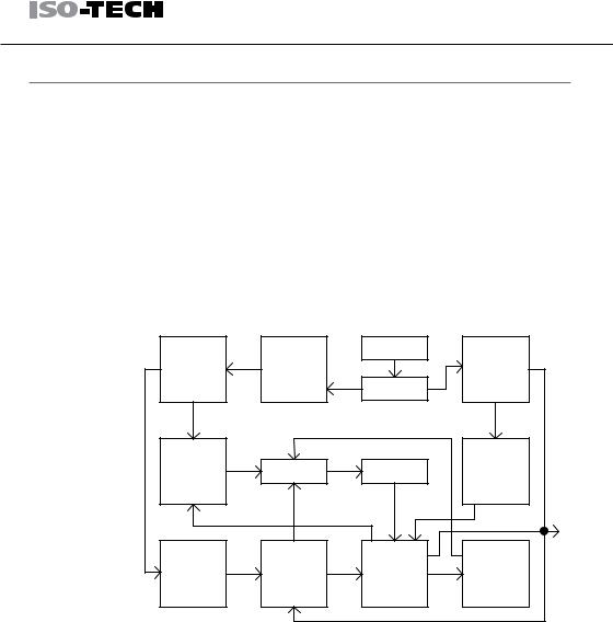
The block diagram below shows the circuit arrangement. The single phase input power is connected to the transformer through the input circuit. Details of each part are described in the next page.
Block diagram
Reference |
Auxiliary |
AC Input |
|
|
|
Relay |
|||
Voltage |
Rectifier & |
|
||
|
Control |
|||
Source |
Filter |
|
||
Transformer |
|
|||
|
|
|
||
Current |
|
|
Main |
|
“OR” Gate |
Amplifier |
Rectifier & |
||
Comparator |
||||
|
|
Filter |
||
|
|
|
||
|
|
|
O/P |
|
Voltage |
Voltage |
Series |
Instant Over |
|
Load |
||||
Amplifier |
Comparator |
Regulator |
||
Protection |
||||
|
|
|
Rectifier |
The auxiliary rectifiers D1011 to D1014 provide bias voltage filtered by |
|
the capacitors C102 and C103, for the pre-regulators U101 and U102. |
|
They provide a regulated voltage for other modules. |
Main Rectifier |
The main rectifier is a full wave bridge rectifier. It provides the power |
|
after the rectifier is filtered by the capacitor C101, and then regulated via |
|
a series-wound regulator, which is finally delivered to the output terminal. |
12 |
|

|
|
|
|
|
OVERVIEW |
|
|
|
|
|
|
||
|
|
|
|
|||
|
|
|
|
|||
|
Current Limiter |
U104 acts as a current limiter. When the current is over predetermined |
||||
|
|
|
|
|
rating, U104 is activated and decreases the current. U208 provides a |
|
|
|
|
|
|
reference voltage. U206 is the inverter amplifier. U103 is a comparator |
|
|
|
|
|
|
amplifier which compares reference voltage and feedback voltage, and |
|
|
|
|
|
|
then delivers to Q102, which then calibrates the output voltage. |
|
|
Overload |
When the unit is overloaded, Q107 activates to control the current |
||||
|
|
|
|
|
magnitude of Q102, to limit the output current. The relay control circuit |
|
|
|
|
|
|
controls the power dissipation in the series-wound regulated circuit. |
|
13
|
|
|
|
|
IPS X303 Series Instruction Manual |
|
|
|
|
|
|
||
|
|
|
||||
|
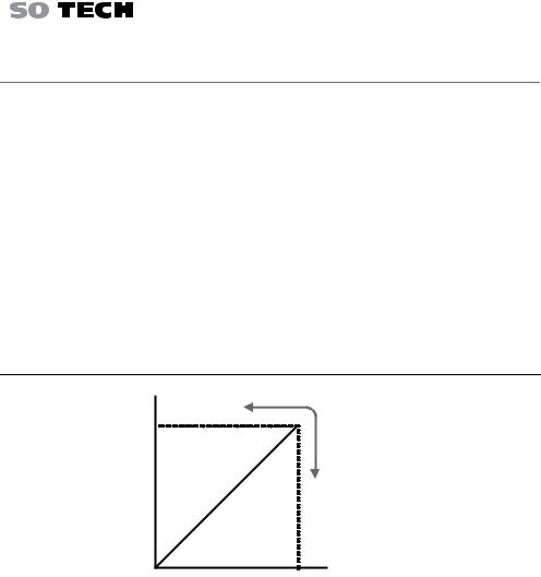
CV/CC Crossover Characteristics |
|||||
|
Background |
The IPS X303 series automatically switches between constant voltage |
||||
|
|
|
|
|
mode (CV) and constant current mode (CC), according to load condition. |
|
|
CV mode |
When the current level is smaller than the output setting, the IPS X303 |
||||
|
|
|
|
|
series operates in Constant Voltage mode. The indicator on the front |
|
|
|
|
|
|
panel turns green (C.V.) The Voltage level is kept at the setting and the |
|
|
|
|
|
|
Current level fluctuates according to the load condition until it reaches |
|
|
|
|
|
|
the output current setting. |
|
|
CC mode |
When the current level reaches the output setting, the IPS X303 series |
||||
|
|
|
|
|
starts operating in Constant Current mode. The indicator on the front |
|
|
|
|
|
|
panel turns red (C.C.) The Current level is kept at the setting but the |
|
Voltage level becomes lower than the setting, in order to suppress the output power level from overload. When the current level becomes lower than the setting, the IPS X303 series goes back to the Constant Voltage mode.
Diagram |
Vout |
|
|
Vmax |
|
|
Constant |
|
|
Voltage |
|
|
Constant |
|
|
Current |
|
|
Imax |
Iout |
|
|
14

FRONT AND REAR PANELS
FRONT AND REAR PANELS |
|
|
|
|
|
|
|
||||
Front Panel Overview |
|
|
|
|
|
|
|
|
|
||
VoltMeter |
Channel |
Ammeter |
Memory Keys |
CH1/CH3, CH2/ |
|
||||||
Indicator |
CH4(Beep) Keys |
|
|||||||||
|
|
|
|
|
|
|
|||||
|
|
|
|
|
DC Power Supply |
MEMORY |
|
|
VOLTAGE |
|
|
|
|
|
|
|
|
|
|
Push |
|
||
|
CH4 |
CH2 |
CH1 |
CH3 |
RECALL/ SAVE |
|
|
|
|||
|
|
|
COARSE/ FINE |
|
|||||||
|
|
|
|
|
|
||||||
|
|
|
|
|
|
|
1 |
CH1/3 |
FINE |
|
Voltage |
|
|
|
|
|
|
|
|
|
|
|
Knobs |
V |
|
|
|
|
V |
|
2 |
CH2/4 |
|
|
|
|
|
|
|
|
|
|
|
BEEP |
|
|
Parallel |
|
|
|
|
|
|
|
3 |
PARA |
|
CURRENT |
|
|
|
|
|
|
|
|
|
|
|||
|
|
|
|
|
|
|
/ INDEP |
|
Keys |
||
|
|
|
|
|
|
|
|
|
|
Push |
|
|
|
|
|
|
|
|
|
|
|
COARSE/ FINE |
Series Keys |
|
|
|
|
|
|
|
4 |
/ INDEP |
FINE |
|
|
|
|
|
|
|
|
|
|
SER |
|
|
|
A |
|
|
|
|
A |
|
|
|
|
|
|
|
|
|
|
|
|
|
LOCK |
OUTPUT |
|
|
Current |
|
|
|
|
|
|
|
UNLOCK |
|
|
|
Knobs |
|
|
|
|
|
|
|
: Long Push |
|
|
|
|
|
|
|
|
|
|
|
|
|
|
|
Output Key |
|
0 |
5V , 1A |
0 |
30V , 3A |
|
0 |
30V ,3A |
|
0 |
5V , 3A |
Lock Key |
|
|
|
|
SLAVE |
|
|
MASTER |
|
5 10V , 1A |
||
|
C.V. |
C.C. |
C.V. |
C.C . PAR. |
|
C.V. |
C.C. |
|
C.V. |
C.C. |
|
POWER |
|
|
|
|
|
|
|
|
|
|
|
|
|
CH4 |
|
CH2 |
GND |
|
CH 1 |
|
CH3 |
|
|
|
|
|
|
SERIES OUTPUT |
COM |
|
+ |
|
|
|
|
|
|
|
|
|
PARA OUTPUT |
|
|
+ |
|
|
|
CH4 Output CH2 Output GND Terminal |
CH1 Output CH3 Output |
|||||||||||||||||||||||||||||||
Power |
CH4 CV/CC |
CH2 CV/CC/PAR |
CH1 CV/CC |
|
|
|
|
CH3 CV/CC |
||||||||||||||||||||||||
Switch |
Indicator |
Indicator |
Indicator |
|
|
|
|
Indicator |
||||||||||||||||||||||||
Display |
|
|
|
|
|
|
|
|
|
|
|
|
|
|
|
|
|
|
|
|
|
|
|
|
|
|
|
|
|
|
|
|
Volt Meter |
Displays output current of each channel. |
|
|
|
|
|
|
|
||||||||||||||||||||||||
|
IPS 4303S: CH1/CH3 and CH2/CH4 |
|
|
|
|
|
|
|
||||||||||||||||||||||||
|
IPS 2303S/3303S: CH1 and CH2 |
|
|
|
|
|
|
|
||||||||||||||||||||||||
|
IPS X303S (5 digits) |
IPS 3303D (3 digits) |
||||||||||||||||||||||||||||||
|
|
|
|
|
|
|
|
|
|
|
|
|
|
|
|
|
|
|
|
|
|
|
|
|
|
|
|
|
|
|
|
|
|
|
|
|
|
|
|
|
|
|
|
|
|
|
|
|
|
|
|
|
|
|
|
|
|
|
|
|
|
|
|
|
|
|
|
|
|
|
|
|
|
|
|
|
|
|
|
|
|
|
|
|
|
|
|
|
|
|
|
|
|
|
|
|
|
|
|
|
|
|
|
|
|
|
|
|
|
|
|
|
|
|
|
|
|
|
|
|
|
|
|
|
|
|
|
|
|
|
|
|
|
|
|
|
|
|
|
|
|
|
|
|
|
|
|
|
|
|
|
|
|
|
|
|
|
|
|
|
|
|
|
|
15
|
|
|
|
|
|
|
|
|
|
|
|
|
|
|
|
|
|
|
|
IPS X303 Series Instruction Manual |
||||||||||
|
|
|
|
|
||||||||||||||||||||||||||
|
|
|
|
|
|
|
|
|
|
|
|
|
|
|
|
|
|
|
|
|
|
|
|
|
|
|
||||
Amp Meter |
Displays output current of each channel. |
|
|
|
|
|
|
|
|
|
|
|||||||||||||||||||
|
|
|
|
|
IPS 4303S: CH1/CH3 and CH2/CH4 |
|
|
|
|
|
|
|
|
|
|
|||||||||||||||
|
|
|
|
|
IPS 2303S/3303S: CH1 and CH2 |
|
|
|
|
|
|
|
|
|
|
|||||||||||||||
|
|
|
|
|
IPS X303S (4 digits) |
IPS 3303D (3 digits) |
||||||||||||||||||||||||
|
|
|
|
|
|
|
|
|
|
|
|
|
|
|
|
|
|
|
|
|
|
|
|
|
|
|
|
|
|
|
|
|
|
|
|
|
|
|
|
|
|
|
|
|
|
|
|
|
|
|
|
|
|
|
|
|
|
|
|
|
|
|
|
|
|
|
|
|
|
|
|
|
|
|
|
|
|
|
|
|
|
|
|
|
|
|
|
|
|
|
|
|
|
|
|
|
|
|
|
|
|
|
|
|
|
|
|
|
|
|
|
|
|
|
|
|
|
|
|
|
|
|
|
|
|
|
|
|
|
|
|
|
|
|
|
|
|
|
|
|
|
|
|
|
|
|
|
|
|
|
|
|
|
|
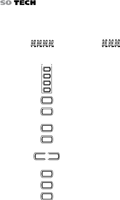
Control Panel
MEMORY
Memory Keys
RECALL /SAVE
1
2
Saves or recalls panel settings. Four settings, 1 to 4, are available. For save/recall details, see page 36.
3
4
CH1/CH2
CH1/3 and
CH2/4
Beep Keys
Parallel/Series
Keys
Lock Key
16
CH1
CH2
BEEP
CH1/3
CH2/4
BEEP
CH2/4 


 CH2
CH2
BEEP BEEP
PARA /INDEP
SER /INDEP
LOCK
UNLOCK
IPS 2303S/3303S: Selects the output channel (CH1/CH2) for level adjustment. For level setting details, see 22.
IPS 4303S: Selects the output channel (CH1/3 and CH2/4) for level adjustment.
Pressing and holding the CH2 (IPS 2303S/3303S) or the CH2/4 key (IPS 4303S) enables the beeper sound. For details, see page 22.
Activates Tracking Parallel operation or Tracking Series operation, For details, see page 28.
Locks or unlocks the front panel keys (excluding the OUTPUT key). Pressing the LOCK key will also exit remote mode if the machine is in remote mode. For details, see page 23.
FRONT AND REAR PANELS
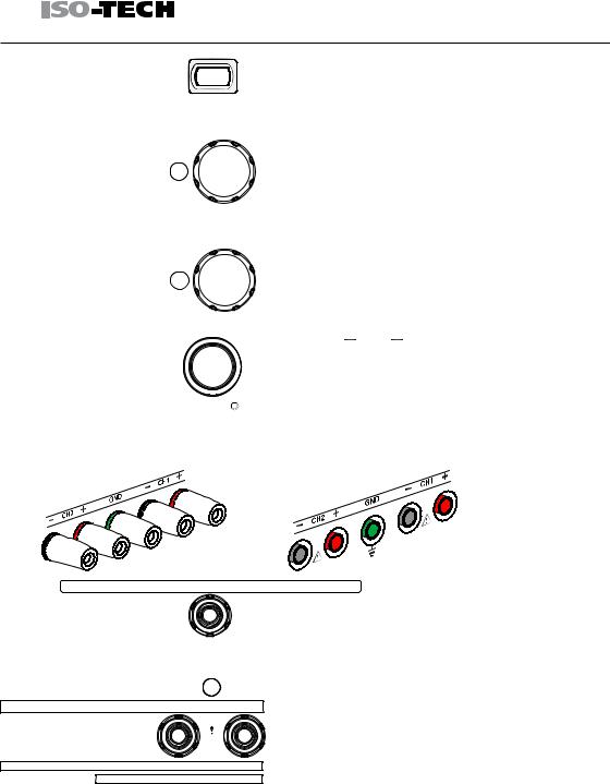
Output Key |
OUTPUT |
|
Voltage Knobs |
VOLTAGE |
Push |
|
|
COARSE/FINE |
|
FINE |
Current Knobs |
CURRENT |
Push |
|
|
COARSE/FINE |
|
FINE |
POWER
Power Switch
Terminals
Default Terminals
GND Terminal |
|
|
GND |
|
|
|
|
CH1 Output |
0 |
|
30V , 3A |
|
MASTER |
||
CH1 CV/CC |
C.V. |
C.C. |
|
|
|||
Indicator |
|
|
CH1 |
CH1 Output |
|
|
|
|
COM |
|
+ |
|
|
|
+ |
Turns the output on or off.
Adjusts the output voltage level for the selected channel. Pressing the knob switches coarse and fine level setting.
Adjusts the output current level for the selected channel. Pressing the knob switches coarse and fine level setting.
Turns On or Off
 the main power. For power up sequence, see page 20.
European Terminals
Accepts a grounding wire.
Indicates CH1 Constant Voltage or Constant Current state.
Outputs CH1 voltage and current.
17
Loading...