Iso-tech IPS-3201, IPS-3202 User Manual

IPS-3201/3202 PROGRAMMABLE POWER SUPPLY
USER MANUAL
Programmable Power Supply
IPS-3201/3202
User Manual
RS Components Ltd
This manual contains proprietary information, which is protected by copyrights. All rights are reserved. No part of this manual may be photocopied, reproduced or translated into another language without prior written consent of RS Components.
The information in this manual was correct at the time of printing. Due to product improvements, RS Components reserves the rights to change specification, equipment, and maintenance procedures at any time without notice.
82IP-32020MA
IPS-3201/3202 PROGRAMMABLE POWER SUPPLY |
|
|
USER MANUAL |
|
|
CONTENTS |
PAGE |
|
1. PRODUCT INTRODUCTION....................................................................................... |
|
1 |
1-1. DESCRIPTION............................................................................................................ |
|
1 |
1-2. FEATURES.................................................................................................................. |
|
2 |
2. TECHNICAL SPECIFICATIONS................................................................................ |
|
3 |
3. OPERATING PRECAUTIONS..................................................................................... |
|
6 |
3-1. UNPACKING THE INSTRUMENT ........................................................................ |
|
6 |
3-2. CHECKING THE SUPPLY VOLTAGE.................................................................. |
|
6 |
3-3. OPERATING ENVIRONMENT............................................................................... |
|
7 |
4. CONTROL PANEL.......................................................................................................... |
|
8 |
5. OPERATION .................................................................................................................. |
|
12 |
5-1. OUTPUT VOLTAGE AND CURRENT SETTING ............................................ |
|
12 |
5-2. OVER VOLTAGE AND OVER CURRENT PROTECTION SETTING.......... |
13 |
|
5-3. VOLTAGE AND CURRENT STEP SETTING: .................................................. |
|
14 |
5-4. INFORMATION STORING AND RECALLING:............................................... |
|
15 |
5-5. INFORMATION EDITING AND COPYING:..................................................... |
|
16 |
5-6. AUTO-OPERATION............................................................................................... |
|
17 |
5-7. PARALLEL OPERATION MODE........................................................................ |
|
19 |
5-8. TRACKING OPERATION MODE........................................................................ |
|
19 |
5-9. RS-232 INTERFACE PARAMETER SETTING.................................................. |
|
20 |
5-10. MAXIMUM OUTPUT SETTING VALUES...................................................... |
|
21 |
5-11.TEST LEADS.......................................................................................................... |
|
21 |
5-12. REMOTE CONTROL VIA THE RS-232 INTERFACE.................................... |
|
21 |
6. MAINTENANCE ........................................................................................................... |
|
22 |
6-1. FUSE REPLACEMENT.......................................................................................... |
|
22 |
6-2. LINE VOLTAGE ADJUSTMENT ........................................................................ |
|
22 |
6-3. CLEANING .............................................................................................................. |
|
23 |
6-4. REPAIR AND CALIBRATION............................................................................. |
|
23 |
– i – |
– i – |

IPS-3201/3202 PROGRAMMABLE POWER SUPPLY
USER MANUAL
SAFETY TERMS AND SYMBOLS
These terms may appear in this manual or on the product:
WARNING. Warning statements identify condition or practices that could result in injury or loss of life.
CAUTION. Caution statements identify conditions or practices that could result in damage to this product or other property.
WARNING: This equipment is not for measurements performed for CAT II, III and IV.
Measurement category I is for measurements performed on circuits not directly connected to MAINS.
Measurement category II is for measurements performed on circuits directly connected to the low voltage installation.
Measurement category III is for measurements performed in the building installation. Measurement category IV is for measurements performed at the source of the low-voltage installation.
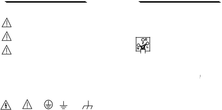
The following symbols may appear in this manual or on the product:
DANGER ATTENTION Protective Earth (ground) Frame or Chassis
High Voltage refer to Manual Conductor Terminal |
Terminal |
Terminal |
|
IPS-3201/3202 PROGRAMMABLE POWER SUPPLY
USER MANUAL
FOR UNITED KINGDOM ONLY
NOTE: This lead/appliance must only be wired by competent persons
WARNING: THIS APPLIANCE MUST BE EARTHED
IMPORTANT: The wires in this lead are colour-coded in accordance with the following code:
Green/ Yellow: |
Earth |
Blue: |
Neutral |
Brown: |
Live (Phase) |
As the colours of the wires in main leads may not correspond with the colour markings identified in your plug/appliance, proceed as follows:
The wire which is coloured Green & Yellow must be connected to the Earth terminal marked with the letter E or by the earth symbol  or coloured Green or Green &
Yellow.
The wire which is coloured Blue must be connected to the terminal which is marked with the letter N or coloured Blue or Black.
The wire which is coloured Brown must be connected to the terminal marked with the letter L or P or coloured Brown or Red.
If in doubt, consult the instructions provided with the equipment or contact the supplier.
This cable/appliance should be protected by a suitably rated and approved HBC mains fuse: refer to the rating information on the equipment and/or user instructions for details. As a guide, cable of 0.75mm2 should be protected by a 3A or 5A fuse. Larger conductors would normally require 13A types, depending on the connection method used.
– ii – |
– iii – |

IPS-3201/3202 PROGRAMMABLE POWER SUPPLY
USER MANUAL
Any moulded mains connector that requires removal or replacement must be destroyed by removal of any fuse & fuse carrier and disposed of immediately, as a plug with bared wires is hazardous if a engaged in live socket. Any re-wiring must be carried out in accordance with the information detailed on this label and in accordance with local regulations. If further information is required, contact the supplier, the address is given at the end of these instructions.
IPS-3201/3202 PROGRAMMABLE POWER SUPPLY
USER MANUAL
1. PRODUCT INTRODUCTION
1-1. Description
The IPS series programmable power supplies are controlled by a Microprocessor Unit (MPU), which can be connected via an in-built RS-232 communication interface to a personal computer. This allows remote operation for automatic testing and control as may be required by the user.
The voltage and current are controlled by a 12 bit D/A converter with high resolution and accuracy. The digital control of the system allows simple and precise entry of information, together with clear and unambiguous monitoring of the instrument parameters.
The over-voltage protection (OVP) and over-current protection (OCP) is set through software and detected by hardware to provide continuous protection for the instrument, external circuits and the user.
– iv – |
– 1 – |

IPS-3201/3202 PROGRAMMABLE POWER SUPPLY
USER MANUAL
1-2. Features
1)Digital control and programmable interface with high resolution and precision.
2)The 192×128 point LCD display can show multiple settings and measurement results simultaneously. The display format may be changed to suit individual requirements.
3)Intuitive interface window display allows convenient operation of the instrument.
4)High stability and low drift.
5)Over voltage, over current and over temperature protection.
6)Intelligent fan speed control
7)Warning signals via built-in buzzer.
8)1/2 rack width for convenient rack installation.
9)Rotary knob for fine and coarse adjustment of settings.
10)100 groups of memories for storing settings.
11)Parallel and series operation modes.
12)Programmable internal timer for output ramp-up, dwell & ramp-down operation.
IPS-3201/3202 PROGRAMMABLE POWER SUPPLY
USER MANUAL
2. TECHNICAL SPECIFICATIONS
SPECIFICATIONS |
IPS-3201 |
|
IPS-3202 |
||
|
Voltage |
0-32V×3 |
|
0-32V×2, 0-6V×1 |
|
Output |
Current |
0-1A×3 |
|
0-2A×2, 0-5A×1 |
|
|
OVP |
0-33V×3 |
|
0-33V×2, 0-7V×1 |
|
|
|
3mV( 5mV rating current>3.0A), test |
|||
|
Voltage |
points are at the +output terminal and –output |
|||
Load effect |
|
terminal point. |
|
|
|
|
3mA( 5mA rating current>3.0A), test |
||||
|
|
||||
|
Current |
points are at the +output terminal and –output |
|||
|
|
terminal point. |
|
|
|
|
Voltage |
3mV, test points are at the +output terminal |
|||
Source effect |
|
and –output terminal point. |
|||
Current |
3mA, test points are at the +output terminal |
||||
|
|||||
|
|
and –output terminal point. |
|||
|
Voltage |
|
10mV |
||
Setting resolution |
Current |
1mA(2mA rating current>3.0A) |
|||
|
OVP |
|
10mV |
||
Program accuracy |
Voltage |
0.05%+20mV |
|||
Current |
0.1%+5mA(+10mA rating current>3.0A) |
||||
(25±5 ) |
|||||
OVP |
0.05%+20mV |
||||
|
|||||
Ripple & noise |
Voltage |
Ripple 1mVrms/3mVp-p |
|||
Noise 2mVrms/30mVp-p |
|||||
(20Hz~20MHz) |
|
||||
Current |
3mArms( 5mArms rating current>3.0A) |
||||
|
|||||
Temperature |
Voltage |
100ppm+3mV |
|||
coefficient |
Current |
100ppm+3mA |
|||
(0~40 ) |
|||||
|
|
|
|
||
Readback |
Voltage |
|
10mV |
||
resolution |
Current |
1mA(2mA rating current >3.0A) |
|||
Response time; |
10%~90% |
|
100ms |
||
Voltage up |
|
|
|
|
|
90%~10% |
100ms ( 10% rating load) |
||||
Voltage down |
|||||
|
|
|
|
||
2 |
3 |

IPS-3201/3202 PROGRAMMABLE POWER SUPPLY
|
|
USER MANUAL |
|
|
|
|
|
Readback |
Voltage |
100ppm+10mV |
|
temperature |
|
|
|
Current |
150ppm+10mA |
||
Coefficient |
|||
|
|
||
Drift |
Voltage |
100ppm+10mV |
|
Current |
150ppm+10mA |
||
|
|||
Tracking |
Tracking error |
0.1%+20mV |
|
|
|
||
operation |
Series |
20mV |
|
|
(Load effect) |
||
|
|
||
|
Program |
Voltage 0.05%+20mV |
|
|
Current 0.1%+10mA |
||
|
accuracy |
||
|
OVP 0.05%+20mV |
||
|
|
||
Parallel |
|
Voltage 3mV( 5mV rating current>3.0A) |
|
Load effect |
Current 6mA, test points are at the +output |
||
operation |
|||
|
terminal and –output terminal point. |
||
|
|
||
|
|
Voltage 3mV,Current 6mA, test points are |
|
|
Source effect |
at the +output terminal and –output terminal |
|
|
|
point. |
|
Memory |
|
Store/Recall points 0~99 |
|
|
Setting time |
0.1sec~99min59sec(max×100) |
|
Timer |
Resolution |
0.1sec |
|
|
Function |
For output working loop (Auto-step running) |
|
Interface |
|
RS232, GPIB interface option |
|
Power source |
100, 120, 220V±10%, 230V +10%/-6% 50/60Hz. AC |
||
Power |
|
IPS-3201: 210W |
|
consumption |
|
IPS-3202: 360W |
|
Mechanical |
Dimensions |
230(W)×140(H)×380(D) mm. |
|
specifications |
Weights |
10 kg |
|
IPS-3201/3202 PROGRAMMABLE POWER SUPPLY
USER MANUAL
SPECIFICATIONS |
IPS-3201 |
|
IPS-3202 |
|
|
Indoor use only |
|
||
|
Altitude: up to 2000 metres |
|||
|
Ambient temperature: |
|
||
Operating |
To satisfy specifications: 10 to 35 ( 50° F to 95°F ) |
|||
environment |
Maximum operating range: 0 to 40 ( 32°F to 104°F ) |
|||
|
Relative humidity: 85% RH(max.), non condensing |
|||
|
Installation Category: II |
|
||
|
Pollution degree: 2 |
|
||
Storage temperature |
-10° to 70 , 70%RH (maximum) |
|||
& humidity |
||||
|
|
|
||
|
Power cable................……….. × 1 |
|||
Supplied accessories |
Instruction manual……………..× 1 |
|||
Programming manual............... × 1 |
||||
|
||||
|
Test leads…..….………………. × 3 |
|||
4 |
5 |
 Loading...