


ISO-TECH IDS-820, IDS-810, IDS-806, IDS-720, IDS-710 User Manual
...IDS-700 & 800 Series Programming Manual
Digital Storage Oscilloscope
IDS-700 & IDS-800 Series
Programming Manual
© 2003 RS Components Ltd. All rights reserved

IDS-700 & 800 Series Programming Manual
Due to continuous improvements in the IDS-700 & 800 series Digital Storage Oscilloscopes, information contained in this manual is subject to change without notice. Contact RS Components for revisions and corrections.
This document supports firmware version v1.07 and previous version
S
RS Components Ltd.
PO Box 99, Corby,
Northants., NN17 9RS
United Kingdom.
Tel: +44 (0) 1536 201234
Fax: +44 (0) 1536 405678
Internet: rswww.com

IDS-700 & 800 Series Programming Manual
1. Introduction
The IDS-820/IDS-840 Digital Storage Oscilloscope can be driven using the GPIB (General Purpose Interface Bus) or the RS-232 serial connection system with a computer. Commands sent over either interface can read or set any IDS-820/840’s instruction. This chapter explains how to carry out the following tasks.
Note: Not all interface options are available on all models – refer to individual product specifications for applicable options.
Notes for GPIB installation
If you are setting up the IDS-820/IDS-840 with a GPIB system, please comply with the following requirements:
Only a maximum of 15 devices can be connected to a single GPIB bus.
Do not use more than 20 m of cable to connect devices to a bus.
Connect one device for every 2 m of cable used.
Each device on the bus needs a unique device address. No two devices can share the same device address.
Turn on at least two-thirds of the devices on the GPIB system while you use the system.
Do not use loop or parallel structure for the topology of the GPIB system.
Notes for RS-232 Configuration
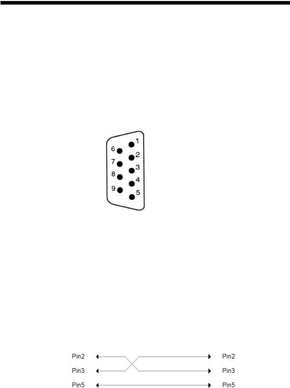
This oscilloscope contains a DB 9-pin, male RS-232 connector for serial communication with a computer or terminal. The RS-232 interface of this oscilloscope is configured as an RS-232 “Data Terminal Equipment”, so that data is sent from pin 3 and received on pin 2. For remote controls, the RS-232 interface has to be connected with a computer or terminal.
Pin Assignments
The pin assignments for RS-232 interface of the IDS-820/IDS-840 series are listed below.
IDS-700 & 800 Series Programming Manual
1No connection
2Receive Data(RxD) (input)
3Transmit Data(TxD) (output)
4No connection
5Signal Ground (GND)
6No connection
7No connection
8No connection
9No connection
Figure 1-1: Pin assignments for the IDS-820’s RS232 connector
DB9 to DB9 Wiring
The wiring configuration is used for computer with DB9 connectors that configured as Data Terminal Equipment.
Figure 1-2: DB9 to DB9 wiring

IDS-700 & 800 Series Programming Manual
When the oscilloscope is set up with an RS-232 interface, please check the following points:
ٛDo not connect the output line of one DTE device to the output line of the other.
ٛMany devices require a constant high signal on one or more input pins.
ٛEnsure that the signal ground of the equipment is connected to the signal ground of the external device.
ٛEnsure that the chassis ground of the equipment is connected to the chassis ground of the external device.
ٛDo not use more than 15m of cable to connect devices to a PC.
ٛEnsure the same configurations are used on the device as the one used on PC terminal.
ٛEnsure the connector for the both side of cable and the internal connected line are met the demand of the instrument.
Computer’s Connection for RS-232
A personal computer with a COM port is the essential facilities in order to operate the digitizing oscilloscope via RS-232 interface.
The connections between oscilloscope and computer are as follows:
I.Connect one end of a RS-232 cable to the computer.
II.Connect the other end of the cable to the RS-232 port on the oscilloscope.
III.Turn on the oscilloscope.
IV. |
Turn on the computer. |
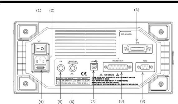
Figure 1-3, shows the GPIB port and RS-232 port’s locations on the rear panel of the IDS-820/IDS-840 Digital storage Oscilloscope.
IDS-700 & 800 Series Programming Manual
Figure 1-3. Rear Panel of IDS-820/840
(1): Main power switch (2): AC power socket (3): GPIB port (option) (4): Fuse drawer
(5): “SELF CAL” BNC output
(6): “GO/NO GO” BNC output (7): USB connector
(8): Printer port (9): RS-232 port
2. Computer Connection
A personal computer with a GPIB card is the essential stuff in order to operate the
IDS-820/IDS-840 via GPIB interface.
Connect between IDS-820/IDS-840 Digital storage Oscilloscope and computer as follows:
I.Connect one end of a GPIB cable to the computer.
II.Connect the other end of the GPIB cable to the GPIB port on the IDS-820/IDS-840
Digital storage Oscilloscope.
III. Turn on the IDS-820/IDS-840 Digital storage Oscilloscope.
IV. Turn on the computer.

IDS-700 & 800 Series Programming Manual
The GPIB interface capabilities:
The GPIB interface of the IDS-820/IDS-840 corresponds to the standard of IEEE488.1-1987, IEEE488.2-1992 and SCPI-1994. The GPIB interface functions are listed as follows:
SH1(Source |
The IDS-820/IDS-840 can transmit multilane messages |
Handshake): |
across the GPIB. |
AH1(Acceptor |
The IDS-820/IDS-840 can receive multilane messages across |
Handshake): |
the GPIB. |
T6(Talker): |
Talker interface function includes basic talker, serial poll, and |
|
unaddress if MLA capabilities, without talk only mode function. |
L4 (Listener): |
The IDS-820/IDS-840 becomes a listener when the controller |
|
sends its listen address with the ATN (attention) line asserted. |
|
The IDS-820/IDS-840 does not have listen only capability. |
SR1 (Service Request): The IDS-820/IDS-840 asserts the SRQ (Service request) line to notify the controller when it requires service.
RL1 (Remote/Local): The IDS-820/IDS-840 responds to both the GTL (Go to Local) and LLO (Local Lock Out) interface messages.
PP0 (Parallel Poll): The IDS-820/IDS-840 has no Parallel Poll interface function.
DC1 (Device Clear): The IDS-820/IDS-840 has Device clear capability to return the device to power on status.
DT0 (Device Trigger): The IDS-820/IDS-840 has no Device Trigger interface function.
C0 (Controller) : The IDS-820/IDS-840 can not control other devices.
GPIB address setting
To change the GPIB address, use the following steps:
Press the UTILITY button on the front panel. The utility menu provides
Interface Menu sub-menu by pressing the F2 soft-key in which the GPIB sub menu

IDS-700 & 800 Series Programming Manual
is included. Press the F1 soft-key to select the GPIB setting menu.
For GPIB sub menu
ٛType GPIB: Select GPIB port.
ٛAddr 1~30: select the appropriate address for GPIB.
ٛPrevious Menu: back to previous menu.
GPIB connection testing
If you want to test the whether the GPIB connection is working or not, use the National Instrument’s “Interactive Control utility” for instance, you communicate with the GPIB devices through calls you interactively type in at the keyboard.
The Interactive Control can help you to learn about the instrument and to troubleshoot problems by displaying the following information on your screen after you enter a command:
ٛResults of the status word (ibsta) in hexadecimal notation
ٛMnemonic constant of each bit set in ibsta
ٛMnemonic value of the error variable (iberr) if an error exists (the ERR bit
is set in ibsta)
ٛCount value for each read, write, or command function
ٛData received from your instrument
You can access online help in Interactive Control by entering help at the prompt, or you can get help on a specific function by entering help <function> at the prompt, where <function> is the name of the function for which you want help.
To start Interactive Control within National Instrument’s “Measurement & Automation Explorer”, complete the following steps:
1Select Tools→I-488.2 Utilities→Interactive Control.
2Open either a board handle or device handle to use for further NI-488.2 calls.
Use ibdev to open a device handle, ibfind to open a board handle, or the set 488.2 command to switch to a 488.2 prompt.
The following example uses ibdev to open a device, assigns it to access board gpib0, chooses a primary address of 7 with no secondary address, sets a timeout of 10 seconds, enables the END message, and disables the EOS mode.

IDS-700 & 800 Series Programming Manual
:ibdev
enter board index: 0 enter primary address: 7
enter secondary address: 0 enter timeout: 13
enter ‘EOI on last byte’ flag: 1 enter end-of-string mode/byte: 0
ud0:
Note: If you type a command and no parameters, Interactive Control prompts you for the necessary arguments. If you already know the required arguments, you can type them at the command prompt, as follows:
:ibdev 0 7 0 13 1 0 ud0:
Note: If you do not know the primary and secondary address of your GPIB instrument, right-click on your GPIB interface in Measurement & Automation Explorer and select
Scan for Instruments. After Explorer scans your interface, it displays your instrument address in the right window panel.
3. After you successfully complete ibdev, you have a ud prompt. The new prompt, ud0, represents a device-level handle that you can use for further NI-488.2 calls. To clear the device, use ibclr, as follows:
ud0: ibclr [0100] (cmpl)
To write data to the device, use ibwrt.ud0: ibwrt "*IDN?"[0100] (cmpl)count: 5
To read data from your device, use ibrd. The data that is read from theinstrument is displayed. For example, to read 28 bytes, enter the following:
ud0: ibrd 28 |
|
|
|
[0100] (cmpl) count: 28 |
|
|
|
47 |
57 2C 20 47 44 53 |
2D , |
IDS- |
38 |
32 30 2C 20 50 39 |
32 |
820, P92 |
30 |
31 33 30 2C 20 56 |
2E |
0130, V. |
31 |
2E 30 39 |
|
1.09 |

IDS-700 & 800 Series Programming Manual
6. When you finish communicating with the device, make sure you put it offline using the ibonl command, as follows:
ud0: ibonl 0 [0100] (cmpl)
: The ibonl command properly closes the device handle and the ud0 prompt is no longer available.
7. To exit Interactive control, type q.
For the details, please refer to National Instrument’s manual.
If you do not receive a proper response from the IDS-820/IDS-840, please check the power is on, the GPIB address is correct, and all cable connections are active,
RS232 connection testing
If you want to test whether the RS-232 connection is working or not, you can send a command from computer. For instance, using a terminal program send the query command
*idn?
should return the Manufacturer, model number, serial number and firmware version in the following format:
RS ,IDS-820,P920130,V.1.09
If you do not receive a proper response from the oscilloscope, please check if the power is on, the RS-232 configurations are the same on both sides, and all cable connections are active.
IDS-700 & 800 Series Programming Manual
3. Remote Control’s Commands
The IDS-820/IDS-840 can be operated from computer via the GPIB port or RS-232 port. The remote commands of IDS-820/IDS-840 are compatible with IEEE-488.2 and SCPI standards partially.
SCPI
SCPI (Standard Commands for Programmable Instruments) is a standard created by an international consortium of the major test and measurement equipment manufacturers. The IEEE-488.2 syntax has been adopted by SCPI to furnish common commands for the identical functions of different programmable instruments.
Common Command & Queries
Syntax & Status Data Structure
 Interface Function
D C B A A B C D
SCPI IEEE-488.1 SCPIIEEE-488.2 IEEE-488.2
Figure 3-1: the relationship between IEEE-488.1, IEEE-488.2, and SCPI.
As shown in the figure 3-1, the IEEE-488.1 standard is located at layer A and layer A belongs to the protocol of interface function on the GPIB bus. The source handshake
(SH), acceptor handshake (AH) and talker are included in this layer (10 interface functions in total). At layer B, the syntax and data structure are the essence of the entire IEEE 488.2 standard. The syntax defines the function of the message communication, which contain the <PROGRAM MESSAGE> (or simply “commands”) and <RESPONSE MESSAGE>. The two kinds of messages represent the syntax format of a device command and return value. The data structure is the foundation of

IDS-700 & 800 Series Programming Manual
the status reporting, which IEEE-488.2 standard have been defined. The common commands and queries are included in layer C. Commands and queries can be divided into two parts: mandatory and optional. Commands modify control settings or tell the instrument to perform a specific action. Queries cause the instrument to send data or status information back to the computer. A question mark at the end of a command identifies it as a query. Layer D is interrelated with device information. Different devices have different functions. SCPI command sets belong to this layer.
Command Syntax
If you want to transfer any of the instructions to an instrument and comply with SCPI, there are three basic elements which must be included as follows.
ٛCommand header
ٛParameter (if required)
ٛMessage terminator or separator
Command Header
The command header has a hierarchical structure that can be represented by a command tree (Figure 3-2).
The top level of the tree is the root level. A root node is located at the root level. A root node and one or more lower-level nodes form a header path to the last node called the leaf node.
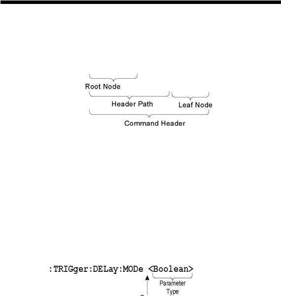
IDS-700 & 800 Series Programming Manual
The command header is configured by header path and leaf node. Figure 3-3 shows the command header for the leaf node.
:TRIGger:DELay:EVENt ?
Figure 3-3: Command header
Parameter
If the command has parameters, the values have to be included. In this manual, when we expressed the syntax of the command, the < > symbols are used for enclosing the parameter type. For instance, the syntax of the command in Figure 8-5 includes the Boolean parameter type
NOTE: Do not include the <, >, or | symbols when entering the actual value for a parameter.
Space
Figure 3-4: Command Header with Parameter
Table 3-1 defines the Boolean and other parameter types for the IDS-820/IDS-840.

IDS-700 & 800 Series Programming Manual
Parameter Type |
Description |
Example |
|
|
|
|
|
|
Boolean |
Boolean numbers or values |
|
|
|
1 0 |
|
|
|
NR1 |
Integers |
0, 1, 18 |
|
|
|
NR2 |
Decimal numbers |
1.5, 3.141, 8.4 |
|
|
|
NR3 |
Floating point numbers |
4.5E-1, 8.25E+1 |
|
|
|
NRf |
NR1, NR2, or NR3 |
1, 1.5, 4.5E-1 |
|
|
|
Table 3-1: Parameter Types for Syntax Descriptions
For the actual value of the parameter type <Boolean>, you have to enter 0 instead of “OFF” or enter 1 instead of “ON”.
The following example includes both the header and a value for the parameter type:
:TRIGger:NREJ 0
Parameter values that appear in this manual are usually separated by a vertical line. This vertical line has the same meaning as the word "or," For example, values for the parameter <Boolean> are
0|1
This is the same as saying "0 (off) or 1 (on)" Any single value is a valid parameter.
Message Terminator and Message Separator
In accordance with the IEEE 488.2 standard, the IDS-820/IDS-840 accepts any of the following message terminators:
^
ٛLF END Line feed code (hexadecimal 0A) with END message
ٛLF Line feed code
ٛ<dab>^END Last data byte with END message
These terminators are compatible with most application programs. A semicolon separates one command from another when the commands appear on the same line.

IDS-700 & 800 Series Programming Manual
Entering Commands
The standards that govern the command set for the IDS-820/IDS-840 allow for a certain amount of flexibility when you enter commands. For instance, you can abbreviate many commands or combine commands into one message that you send to the IDS-820/IDS-840. This flexibility, called friendly listening, saves programming time and makes the command set easier to remember and use.
Command Characters
The IDS-820/IDS-840 is not sensitive to the case of command characters. You can enter commands in either uppercase or lowercase.
You can precede any command with white space characters. You must, however, use at least one space between the parameter and the command header.
Abbreviating Commands
Most commands have a long form and a short form. The listing for each command in this section shows the abbreviations in upper case. For instance, you can enter the query
:TIMebase:SCALe ?
simply as
:TIM:SCAL ?
Combining Commands
You can use a semicolon (;) to combine commands and queries. The IDS-820/IDS-840 executes coherent commands in the order it receives them. When you coherent queries, the IDS-820/IDS-840 will combine the responses into a single response message. For example, if the frequency and amplitude of the signal are equal to 100kHz and 1V, the command
:MEASure:FREQuency?;:MEASure:VAMPlitude?
returns the message
100kHz 1v

IDS-700 & 800 Series Programming Manual
4. Details of Command Reference
Each command in this chapter will be given a brief description. The examples of each command will be provided and what query form might return.
*CLS (no query form)
Clears all event status data register. This includes the Output Queue, Operation Event Status Register, Questionable Event Status Register, and Standard Event Status Register.
Syntax
*CLS
Examples
*CLS clears all event registers.
*ESE
Sets or returns the bits in the Event Status Enable Register (ESER). The ESER enables the Standard Event Status Register (SESR) to be summarized on bit 5 (ESB) of the Status Byte Register (SBR).
Syntax
*ESE<NR1> *ESE?
Arguments
<NR1> is a number from 0 to 255. The binary bits of the ESER are set according to this value.
Returns
<NR1> is a number from 0 to 255 that indicates the decimal value of the binary bits of the ESER.
Examples
*ESE 65 sets the ESER to binary 0100 0001.If the ESER contains the binary value
1000 0010, the *ESE? will return thevalue of 130.
*ESR? (query only)

IDS-700 & 800 Series Programming Manual
Returns and clears the contents of the Standard Event Status Register (SESR). Syntax
*ESR?
Returns
<NR1> is a number from 0 to 255 that indicates the decimal value of the binary bits of the ESER.
Examples
If the ESER contains the binary value 1100 0110, the *ESR? will return the value of 198.
*IDN? (query only)
Returns the unique identification code of the IDS-820/IDS-840.
Syntax
*IDN?
Examples
*IDN?
Returns ,IDS-820/IDS-840,0,<Firmware version>
*LRN? (query only)
Returns the string that the IDS-820/IDS-840 settings will be listed.
Syntax
*LRN?
Returns

IDS-700 & 800 Series Programming Manual
The command form (*OPC) sets the operation complete bit (bit 0) in the
Standard Event Status Register (SESR) when all pending operations finish. The query
form (*OPC?) tells the oscilloscope to place an ASCII 1 in the Output Queue when the
oscilloscope completes all pending operations.
Syntax
*OPC *OPC?
Returns *RCL
Recall the setting data from memory which were previously saved. The settings of the RS-232 (or GPIB) can be stored in memories M1 to M15. However, if the user recalls a stored memory in which the settings of the RS-232 or GPIB are different to the present settings, the RS-232 (or GPIB) settings will remain unchanged. The current RS-232 (or GPIB) settings will not to be affected by the recalled setting of RS-232 (or GPIB) for the moment.
Syntax
*RCL <NR1>
Arguments: 1~15
Examples
*RCL 1 recalls the setting data located at thefirst position of memory address.
*RST (no query form)
Sets all control settings of the oscilloscope to their default values, but does not purge stored setting.
 Loading...