


 Loading...
ISO-TECH IDS-820, IDS-810, IDS-806, IDS-720, IDS-710 User Manual
...IDS-706/710/720/806/810/820 Operation Manual
Digital Storage Oscilloscope
IDS-700 & IDS-800 Series
Operation Manual
© 2003 RS Components Ltd. All rights reserved
82DS-81000MA
0

IDS-706/710/720/806/810/820 Operation Manual |
|
Table of Contents |
Pages |
1. USAGE PRECAUTIONS AND RECOMMENDATIONS....... 2 |
|
2. GENERAL DESCRIPTION AND FEATURES |
........................ 6 |
3. FIRST TIME OPERATION........................................................ |
9 |
4. PANEL DESCRIPTION ............................................................ |
11 |
5. OPERATION .............................................................................. |
17 |
6. BLOCK DIAGRAM................................................................... |
61 |
7. RS-232 CONFIGURATION ...................................................... |
62 |
8. SPECIFICATIONS .................................................................... |
65 |
Due to continuous improvements in the IDS-706/710/720/806/810/820 Digital Storage Oscilloscopes, information contained in this manual is subject to change without notice. Contact
RS Components for revisions and corrections.
This document supports firmware version v1.07 and previous version
RS Components Ltd.
PO Box 99, Corby,
Northants., NN17 9RS
United Kingdom.
Tel: +44 (0) 1536 201234
Fax: +44 (0) 1536 405678
Internet: rswww.com
1
IDS-706/710/720/806/810/820 Operation Manual
1. Usage Precautions and Recommendations
The following precautions are recommended to ensure your safety and to provide the best conditions for this instrument. If this equipment is used in a manner not specified by the manufacturer, the protection provided by the equipment may be impaired.
Safety Terms and Symbols
These terms may appear in this manual or on the product:
WARNING: Warning statements identify condition or practices that could result in injury or loss of life.
CAUTION: Caution statements identify conditions or practices that could result in damage to this equipment or other property.
The following symbols may appear in this manual or on the equipment:
DANGER |
ATTENTION |
Protective |
Frame |
Earth (ground) |
|
|
|
|
|
High Voltage |
Refer to |
Conductor |
or Chassis Terminal |
Terminal |
|
Manual |
Terminal |
|
|
2

IDS-706/710/720/806/810/820 Operation Manual
FOR UNITED KINGDOM ONLY
NOTE: This lead / appliance must only be wired by competent persons
WARNING: THIS APPLIANCE MUST BE EARTHED
IMPORTANT: The wires in this lead are colour-coded in accordance with the following code:
Green/ Yellow: |
Earth |
|
Blue: |
Neutral |
|
Brown: |
Live (Phase) |
|
As the colours of the wires in main leads may not |
correspond with the coloured marking identified in your plug/appliance, proceed as follows: |
|
The wire which is coloured Green & Yellow must be connected to the Earth terminal marked with the letter E or by the earth symbol  or coloured Green or Green & Yellow. The wire which is coloured Blue must be connected to the terminal which is marked with the letter N or coloured Blue or Black.
The wire which is coloured Brown must be connected to the terminal marked with the letter L or P or coloured Brown or Red. If in doubt, consult a competent electrician or contact RS Components for further advice.
This cable/appliance should be protected by a suitably rated and approved HBC mains fuse: refer to the rating information on the equipment and/or user instructions for details. As a guide, cable of 0.75mm2 should be protected by a 3A or 5A fuse. Larger conductors would normally require 13A types, depending on the connection method used.
Any moulded mains connector that requires removal or replacement must be destroyed by removal of any fuse & fuse carrier and disposed of immediately, as a plug with bared wires is hazardous if engaged in live socket. Any re-wiring must be carried out in accordance with the information detailed on the wiring label, this Instruction Book and comply with current wiring regulations.
3

IDS-706/710/720/806/810/820 Operation Manual
Use and Care
CAUTION
•Do not exceed 300Vpeak into the channel BNC INPUTs
•To avoid risk of fire hazard and electrical shock, a hazardous live voltage must never be connected to the negative side (reference side) of the BNC measuring terminals.
•Do not place any heavy object on the instrument.
•Avoid severe impacts or rough handling that could damage the instrument.
•Use electrostatic discharge precautions while handling and making connections to the instrument.
•Do not place wires into the connectors of the instrument; use only the correct mating connectors and adapters.
•Do not block or obstruct the cooling fan vents on the side or rear panel of the instrument.
1)Disassembly of the Instrument
•Do not disassemble the instrument. If repair or calibration is required, contact RS Components for advice.
2) AC Power Input
CAUTION
•The a.c.input should be within the range of selected line voltage ±10%.
•Ensure the correct fuse is installed prior to applying voltage for the first time –
For 100 V ~ 240 VAC input: Fuse rating is:
Anti-surge 2A / 250V High Breaking Capacity type (HBC), 20 x 5 mm.
4

IDS-706/710/720/806/810/820 Operation Manual
3) Grounding
WARNING
• To avoid electrical shock, the power cord protective grounding conductor must be connected to earth ground.
4) Fuse Replacement
WARNING
•For continued fire protection, replace the fuse with the specified type and rating only.
•Disconnect the power cord before replacing the fuse.
•Use a flat blade screwdriver to open the fuse drawer on the a.c. inlet socket.
•If the fuse has blown, there is a fault. Investigate and rectify the cause of the fault before replacing the fuse.
•Replace the fuse.
5) Cleaning
•Disconnect AC Power Cord from the instrument before cleaning.
•Use a soft cloth dampened in a solution of mild detergent and water. Do not allow any liquid to enter the instrument.
•Do not use chemicals or cleaners containing benzene, toluene, xylene, acetone or other harsh chemicals.
5

IDS-706/710/720/806/810/820 Operation Manual
6) Operating Environment
•Use of this instrument outside the recommended operating conditions may impair the safety provided for the user.
•The following conditions are recommended for optimum use of the instrument -
|
Indoor Use |
Altitude < 2000 m |
Temperature 0° to 50° C |
|
Relative Humidity < 80% |
No direct sunlight |
No strong magnetic fields |
|
Dust Free |
|
|
• |
Installation Category: 300V Cat.II* |
|
|
• |
Pollution degree: 2 |
|
|
7) |
Storage Environment |
|
|
•The following conditions are recommended for optimum storage of the instrument -
Indoor |
Temperature -20° to 70° C |
Relative Humidity < 80% |
WARNING
This is a Class A product. In a domestic environment this instrument may cause radio and/or television interference in which case the user may be required to take adequate corrective measures.
*: Measurement category IV is for measurement performed at the source of low-voltage installation Measurement category III is for measurement performed in the building installation
Measurement category II is for measurement performed on the circuits directly connected to the low voltage installation
2. General Description and Features
The IDS-706, 710, 720, 806, 810 and 820 oscilloscopes are versatile, 2 channel digital storage instruments with the following features:
60MHz, 150MHz, (250MHz for IDS-720 & 820) repetitive bandwidth and 100MSa/s sample rate per channel (25GSa/s E.T. sample rate per channel).
zUp to 10ns peak detection for glitch capture.
6

IDS-706/710/720/806/810/820 Operation Manual
zA large 5.7” mono or colour LCD display (monochrome display for IDS-706, 710, and 720, colour display for IDS-806, 810 and IDS-820).
zTwo input channels, each with a record length of 125k points and 8 bits vertical resolution. Both channels acquire waveforms simultaneously.
zTime base: 1ns/div~10s/div.
z6-digit frequency counter.
zAuto-set for quick setup operation.
zThree Acquisition modes: Sample, peak detect, and average mode.
zCursors and 15 continuously updated automatic measurements: Vhi, Vlo, Vmax , Vmin , Vpp, Vaverage, Vrms, Vamp , rise time, fall time, duty cycle, frequency, period, positive width, negative width.
z15 memory sets for front panel setting save & recall.
z2 memory sets for waveform trace save & recall.
zFFT spectrum analysis.
zTwo useful “Program mode” and “Go, No-Go” function are included.
zAdvanced video and pulse width trigger.
zA large 8 ×12 divisions menu off waveform display graticule.
zRS-232, parallel printer port and USB output are included as standard on all models.
7

IDS-706/710/720/806/810/820 Operation Manual
The IDS-706, 710, 720, 806, 810 & 820 advanced 32-bit microprocessor controlled Digital Storage Oscilloscopes have been designed for a wide range of applications in educational, service and industrial applications. The instruments offer a combinations of trigger control, frequency response, time base versatility and other functions to facilitate measurements and observations, which are generally only available on more expensive oscilloscopes. For ease of operation an “Autoset” function allows for signal related automatic setup of measuring parameters. On-screen readouts and cursor functions for voltage, frequency and frequency related measurement provide extraordinary operational convenience. Fifteen different user defined instrument settings can be saved and recalled without restriction. The built-in RS-232 serial interface allows for remote controlled operation by a PC. A six-digit frequency counter provides extra functionality. The standard USB port permits the “dump” of the entire contents of the instruments’ LCD screen to computer via specific software. A “Program” mode is provided to record all the necessary waveform measuring operations and replay all steps as required. The additional “Go, No-Go” function allows for a simple semi-automated comparison of waveforms with predetermined limits.
8
IDS-706/710/720/806/810/820 Operation Manual
3. First Time Operation
The following text assumes that the “SAFETY” section of this manual has been read carefully and understood.
Each time before the instrument is put into operation, check that the oscilloscope is connected to protective earth. For this reason the power cable must be connected to the oscilloscope and the power outlet first. Next, connect the test lead(s) to the oscilloscope input(s). Check that the equipment or unit under test is switched off and connect the test lead(s) to the test point(s). Lastly, switch on the instrument and afterward the equipment or device under test.
The oscilloscope is switched on by a single press of the ON/STBY button (Before depressing the ON/STBY button on the front panel, ensure the main power switch on the rear panel is switched on). After a few seconds the oscilloscope will initialize and revert to its last used operating mode.
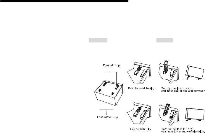
Tilt-stand: For desktop use, lock the tilt-stand in place as shown in the following diagrams:
Figure 3-1: Tilt-stand operation
9
IDS-706/710/720/806/810/820 Operation Manual
Probe calibration
To display an undistorted waveform on an oscilloscope, the probe must be matched to the individual input impedance of each vertical amplifier.
For this purpose a square wave signal with a very fast rise time and minimum overshoot should be used, as the sinusoidal contents cover a wide frequency range.
The build-in compensation signal generator provides a square wave signal with a very fast rise time, and frequency of approx. 1kHz from the output socket below the LCD screen. As the square wave signals are used for probe compensation adjustment, neither the frequency accuracy nor the pulse duty factor are of importance and therefore not specified.
The output provides 2Vpp±3% for a 10:1 probe. When the Y deflection coefficient is set to 50mV/div, the calibration voltage corresponds to a vertical display of 4 divisions (10:1 probe). Connect the probe to the probe calibration output and check the waveform indicates correct compensation (see Figure 3-2). If the waveform indicates over or under compensation, refer to the instructions for the probe and adjust the compensation.
incorrect |
correct |
incorrect |
Figure 3-2: Probe compensations
10

IDS-706/710/720/806/810/820 Operation Manual
AUTOSET
The “Autoset” function provides a stable, triggered display of almost any input signal. Connect a signal to either the channel 1 or channel 2 input BNC connectors and press the AUTOSET button. Table 3-1 shows the defaults of “Autoset” function.
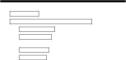
Table 3-1: Defaults of “Autoset” function
Control parameter:
Acquire
Acquire stop after
Display style
Display format
Horizontal position
Horizontal Scale
Trigger coupling
Trigger level
Trigger position
Trigger slope
Trigger source
Trigger type
Vertical bandwidth
Vertical coupling
Vertical offset
Vertical scale
Modified by Autoset to:
Sample
RUN/STOP button only
Vectors
YT
Centered within the graticule windows
As determined by the signal frequency
DC
Midpoint of trace for the trigger source
Center
Positive
Highest frequency of available channels
Edge
Full
DC or AC (dependent on the signal)
0 V
As determined by the signal level
4. Panel Description
Front Panel
11

IDS-706/710/720/806/810/820 Operation Manual
12
IDS-706/710/720/806/810/820 Operation Manual
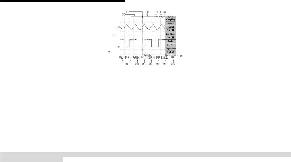
Display Area
(1): The memory bar (500 points processed by oscilloscope)*. (2): Trigger position (T) indicator
(3): Viewable area shows segment of memory bar currently displayed*. Please refer page 38 for details. (4): Run/Stop mode indicator
(5): Trigger status
(6): Trigger level indicator (7): Channel position indicator (8): Delay trigger indicator
(9): Status display for channel 1 & 2 (10): Sample rate status readout (11): Horizontal status readout
(12): Trigger source and status readout (13): Trigger type and mode readout (14): Acquisition status
(15): Interface type indicator (16): Trigger Frequency counter
*: The memory bar length is always 500 points under RUN mode, even when the memory length is set greater than 500 points. The oscilloscope will display 250 points or 300points (menu off) on the LCD screen waveform area.
13
IDS-706/710/720/806/810/820 Operation Manual
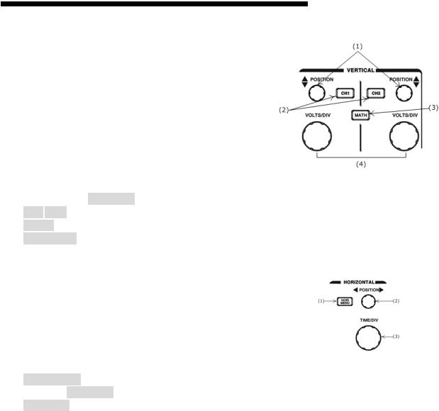
Vertical controls
(1): Channel 1 and 2 POSITION knobs. The position control knobs adjust the vertical position of the channel 1 and channel 2 waveforms on the screen. (2): CH1, CH2 Menu pushbutton. Shows the vertical waveform function and selects the waveform on or off the screen.
(3): MATH function pushbutton. Selects the various math functions available. (4): VOLTS/DIV knobs. Adjusts the vertical scale of the waveforms.
Horizontal controls
(1): HORI MENU. Selects the horizontal functions.
(2): Horizontal POSITION knob. Adjusts waveform horizontal position on the screen. (3): TIME/DIV knob. Adjusts the horizontal scale of selected waveform.
14
IDS-706/710/720/806/810/820 Operation Manual
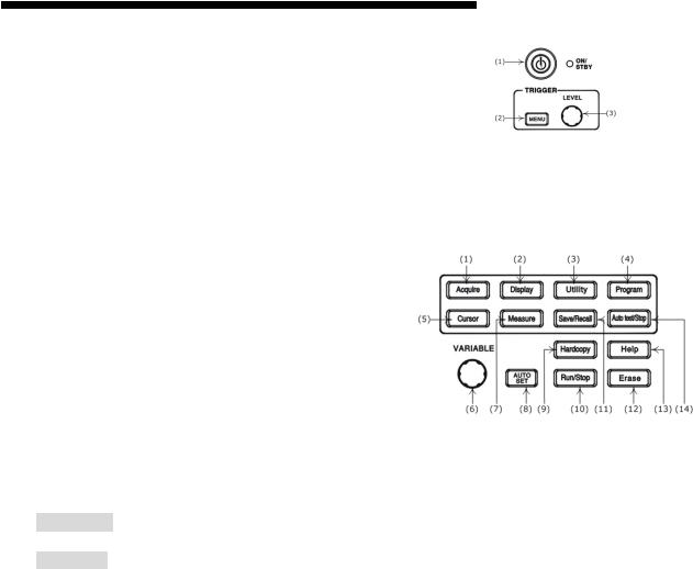
Trigger controls
(1): The power ON/STANDBY pushbutton. (2): Selects the trigger type, source and mode. (3): Trigger level adjustment.
Miscellaneous controls
(1): Select the acquire modes. (2): Control the display modes. (3): Select the utility functions. (4): Sets the Program mode.
(5): Select the cursor types.
(6): VARIABLE knob. Multi-function knob which controls many menu functions. (7): Access the 15 automatic measurement modes.
(8): AUTOSET pushbutton automatically adjusts setup values to display a signal. (9): Printout a hardcopy of the LCD display.
(10): Start and stop waveform acquisition. (11): Save and recall the setups and waveforms. (12): Erases the stationary waveform display.
(13): Display build-in help files on the LCD screen. (14): Stop the replay for Program mode.
15

IDS-706/710/720/806/810/820 Operation Manual
BNC inputs
(1): The channel 1 & 2 BNC inputs receive electrical signals for display. (2): Ground.
(3): Connects an external trigger signal to the oscilloscope.
Rear Panel
(1): Main power switch. (2): AC power inlet. (3): Fuse drawer.
(4): “SELF CAL” output BNC (output range: 0~±2V DC).
(5): “GO/NO GO” output BNC (open collector output, a 10μs pulse will be generated, if certain conditions is met, please refer to page 46 for details) (6): USB connector
(7): Printer port (8): RS-232 port
16
IDS-706/710/720/806/810/820 Operation Manual
5. Operation
This chapter contains useful information about the operation of this oscilloscope.
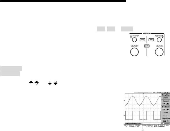
Vertical Control
All vertical operations affect the selected waveform. Press the CH1, CH2, or MATH pushbutton to adjust and select the waveform scale and position.
Figure 5-1: The vertical controls panel
VOLTS/DIV: The VOLTS/DIV knobs adjust the vertical scale (in a 1-2-5 sequence) of the selected waveforms (channel 1 and channel 2).
POSITION: The position control knobs adjust the vertical position of the channel 1 & 2 waveforms. When the vertical position is adjusted, the channel position indicator  or
or  (located on the left side of the LCD graticule) will change position simultaneously. When the channel position indicator reaches the vertical border (top or bottom) of the LCD graticule, the indicator will change shape to “ , ” or “ , ”. The vertical scale information will also be displayed on the LCD screen.
If the position of channel 1 (or channel 2) is changed, the vertical position will be displayed above the status display area of the screen (1).
Figure 5-2: Operating the position knob
17
IDS-706/710/720/806/810/820 Operation Manual
CH1, CH2: The vertical menu contains the following items when channel 1 or channel 2 is selected. These two pushbuttons also switch the waveform display of channel 1 or channel 2 on or off. When channel 1 (or channel 2) is turned on, the CH1 (or CH2) button will be illuminated, and vice versa.
zCoupling /
/ /
/
 : Press the F1 softkey to select AC (
 ) or DC (
 ) coupling, or ground (
 ).
).
zInvert On/Off: Press the F2 softkey to select to turn (waveform) invert on or off.
zBw Limit On/Off: Press the F3 softkey to switch between 20MHz or full bandwidth.
zProbe 1/10/100: Press the F4 softkey to select the probe attenuation ×1, ×10, or ×100 as appropriate.
zImpedance 1MΩ: Input impedance display.
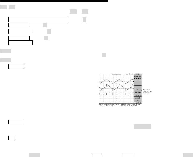
MATH: Select a formula from the math menu: CH1+CH2, CH1-CH2 or FFT (Fast Fourier Transform). You can convert a time-domain signal into its frequency components by an advanced FFT math function. The Math menu contains the following items by pressing F1 softkey after math function is selected. The display of the mathematical waveform can be disabled by pressing
MATH pushbutton again.
zCH1+CH2: Waveform of channel 1 plus waveform of channel 2.
Figure 5-3: Operating the math function (Channel 1 + channel 2)
zCH1-CH2: Algebraic sum of channel 1 and channel 2.
The position of CH1+CH2/CH1-CH2 mathematical waveform can be adjusted by rotating the VARIABLE knob. The math position indicator  (located on the left side of the LCD graticule) will change the position simultaneously. The information of mathematical division and units will also be displayed on the math menu bar.
zFFT: The details of FFT operations are as follows:
FFT
Operation: Push the MATH button to select the FFT function. The Source Channel and Window algorithm can be selected. Press the MATH pushbutton again to disable FFT spectrum
18
IDS-706/710/720/806/810/820 Operation Manual
display.
zSource CH1/CH2: Selects the channel assigned to the FFT spectrum.
zWindow Rectangular/Blackman/Hanning/Flattop:
z Window Rectangular: Transform to rectangular windowing mode. This windowing mode is suitable for transient analysis.
z Window Blackman: Transform to Blackman window mode. The peak resolution of Blackman window mode is not as fine as Hanning mode, however, the response shape flares-out less at low levels and rejection of sidelobes is better.
z Window Hanning: Transform to Hanning window mode. Higher frequency resolution is available when using this mode. z Window Flattop: Transform to flattop windowing mode. This mode can obtain higher magnitude accuracy.
19
IDS-706/710/720/806/810/820 Operation Manual
zPosition: Adjust the FFT position on the display area by rotating the VARIABLE knob. The “ ” math position indicator which located on the left side of LCD screen always points to 0 dB approximately, where 0dB is defined as 1Vrms.
zUnit/div 20/10/5/2/1 dB: Press F5 softkey to expand the FFT spectrum vertically. Expansion factors are 20dB/Div, 10dB/Div, 5dB/Div, 2dB/Div and 1dB/Div.
FFT spectrum measurement using cursors: FFT spectrum’s magnitude (dB) and frequency (Hz) can be measured by using the cursors. Press the CURSOR pushbutton and select Source
MATH by pressing the F1 softkey.
zSource MATH: Selects FFT spectrum cursor measurement function.
zHorizontal  /
/ /
/ /
/
 : Adjust vertical cursors by rotating the VARIABLE knob. The reference values are also shown on the LCD screen: f1: first cursor frequency indication.
f2: second cursor frequency indication.
: The difference value of f1 and f2. Div: frequency per division at present.
For more detail operations, please refer to page 53.
zVertical /
/ /
/ /
/ : Adjust horizontal cursors by rotating the VARIABLE knob. The reference values are also shown on the LCD screen: The colour of two horizontal cursors will be changed to red for the colour oscilloscope.
M1: magnitude indication of first cursor. M2: magnitude indication of second cursor.
: The difference value of M1 and M2.
For more detail operations, please refer to page 53.
20
Loading...