

Page 1
User’s Guide
TOTAL CONTROL
TM
Installation and Programming Guide for
6, 9, 12, 15, 18 and 24 Station Controllers
(Indoor and Outdoor Models)
English • Español • Français
Page 2

i
Thank you for purchasing a Total Control irrigation system controller.
Listed below are some important features you should be aware of
before you begin programming. Details on how to implement these
features are described on the following pages.
• Four fully independent programs that can run concurrently
• Watering day scheduling by Weekdays, Odd/Even days (with
selective day removal) or Day Interval from 1 to 30 days.
• 365-day calendar with automatic compensation for leap year
• Sixteen total start times to use in any program
• Start time stacking overlap protection within each program
• Station watering time from 0 minutes to 10 hours in 1-minute
increments
• Program information erase feature selectable by program
• Non-volatile program memory retains programming information
for up to 30 years without power
• Battery backup maintains time and date during a power failure for
over 2000 continuous hours on a single 9-volt alkaline battery.
• Water budgeting from 0 to 200% in 10% increments
• Rain delay programmable to 7 days
• Self-diagnostic electronic circuit breaker that identifies and overrides faulty stations
• Master valve/pump start operation selectable per program
• Complete manual operations available by station and program
• Sensor switch connection for operation with any normally-closed
rain switch device
• Slide switch control provided for rain switch sensor override
• Modular design for ease of programming, installation and service
To take full advantage of all Total Control features, please review the
User’s Guide completely before programming or installing your new
controller.
FEATURES
Features
Page 3

1
Features....................................................................................................i
Controller Components.....................................................................2–3
General Information..........................................................................4–6
How the Backup System Works.......................................................4
How the Electronic Circuit Breaker Works.....................................5
How the Sensor Feature Works.......................................................6
Programming the Controller...........................................................7–15
Getting Started.............................................................................7–9
Setting the Current Time and Date...............................................10
Erasing Any Prior Programs...........................................................11
Setting the Station Run Time........................................................11
Master Valve/Pump Start On/Off..................................................12
Setting Program Start Times....................................................12–13
Selecting the Days to Water....................................................13–15
Operating the Controller ...............................................................15–18
Water Budget..................................................................................15
Manual Operations.........................................................................16
Off and Rain Delay modes.......................................................17–18
Installation Procedures ..................................................................18–24
Selecting an Installation Site.........................................................18
Mounting the Controller.........................................................19–20
Installing Electrical Conduit ..........................................................20
Connecting the Valve Wiring........................................................21
Connecting a Pump Start Relay....................................................22
Connecting a Rain Shut-Off Sensor..............................................23
Connecting an Earth Ground........................................................23
Connecting the Power Wires.........................................................24
Troubleshooting..............................................................................25-26
Fuse Replacement................................................................................27
Specifications........................................................................................28
TABLE OF CONTENTS
Table of Contents
Page 4

2
Controller Components
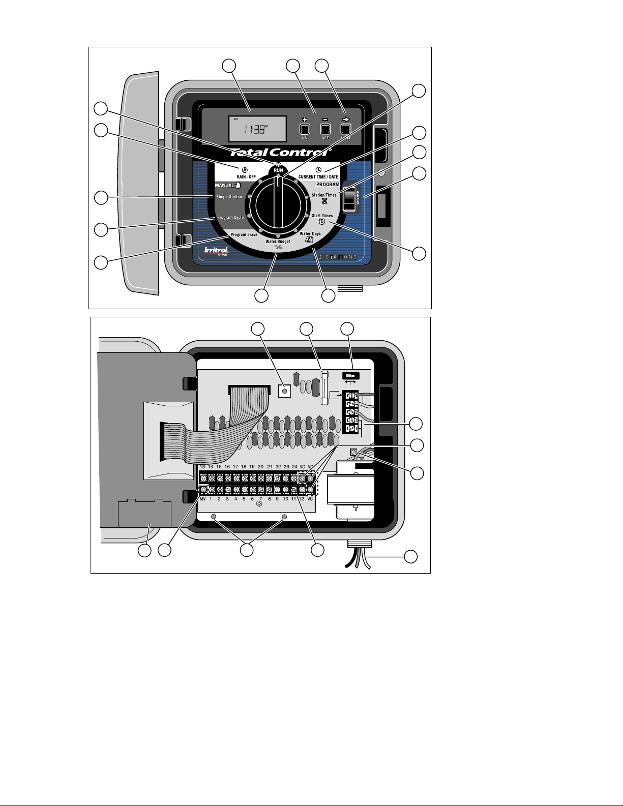
▲ FIGURE 1
1 LCD Display: For viewing time, program and status information.
2 + /On & – /Off Buttons: For entry of program information.
3 Next Button : For selection of information to be programmed or reviewed.
4 Function Dial: For selecting the programming and operating functions.
5 Current Time/Date : For setting the current time and date.
6 Station Times : For setting individual watering time for each station.
7 Program Select Switch: For selection of programs A, B, C or D.
8 Start Times : For setting the time each program cycle will start.
9 Water Days : For setting a watering day schedule for each program.
10. Water Budget : For the increase or decrease of station times for all
stations within a program without changing program memory.
11 Program Erase: For erasing information within a selected program.
12 Manual Program Cycle: For starting manual operation of a selected
program watering cycle.
13 Manual Single Station: For timed or untimed operation of a single station.
14 Rain/Off : For immediate shut down of all controller output.
Programmable output delay for 1–7 days (Rain Delay).
15 Run : For automatic operation.
▲ F
IGURE 2
16 Mounting Holes: Pilot screw holes for attaching the outdoor controller to the
wall. For indoor controller mounting holes, see page 19 Figure 4.
17 Safety Fuse: Replaceable 2.0A slow-blow fuse provides protection from an
internal short-circuit condition.
18 Sensor Control Switch: To override rain switch sensor input.
19 Sensor Connection Terminals: For the connection an optional (normally-
closed)rain switch device.
20 Valve Common Terminals: For the connection of up to three field (24V)
common wires.
21 Earth Ground Lug: For connection of a 16–12 gauge (1.0–2.0mm
2
) copper
ground wire to an earth ground.
22 1/2" NPT Conduit Nipple: For the connection of an electrical conduit
access body for input power wiring. Applicable to outdoor models only.
23 Valve Wire Terminals: For the connection of valve control wires.
24 Master Valve Terminal: For the connection of a master valve or pump start
relay control wire.
25 Battery Compartment: 9-volt alkaline battery access compartment.
Note: Plug-in power transformer for indoor controller not shown.
CONTROLLER COMPONENTS
Page 5
3
ACTIVE
24V
EARTH
GND
AC
G
N
D
BYPASS
SENSOR
SENSOR
VALVE
TEST
1
2
3
4
5
6
7
8
9
10
12
11
13
14
15
16
17
18
19
20
21
22
23
16
24
25
Figure 1
Figure 2
Controller Components
Page 6
4
This section contains general information on:
• How the backup system works
• How the electronic circuit breaker works
• How the sensor feature works
HOW THE BACKUP SYSTEM WORKS
The Total Control uses non-volatile memory to store watering
programs. This type of memory prevents the watering program
information from becoming lost in the event of a power failure. An
additional benefit of non-volatile memory is that a factory-installed
backup program is not necessary, thereby avoiding the potential for
unplanned operation.
Because the current time and date are always changing, only the most
recent date can be saved in non-volatile memory. Therefore, a battery
is required to maintain the correct time and date in the event of a
power failure. A 9-volt alkaline battery (not provided) will maintain
the correct time and date during power failures up to 90 days. In a
typical installation, the battery should last from two to four years
before replacement is necessary. Once the battery or AC power is
connected, the controller can be fully programmed for operation.
Note: For operation of the valves, AC power must be applied.
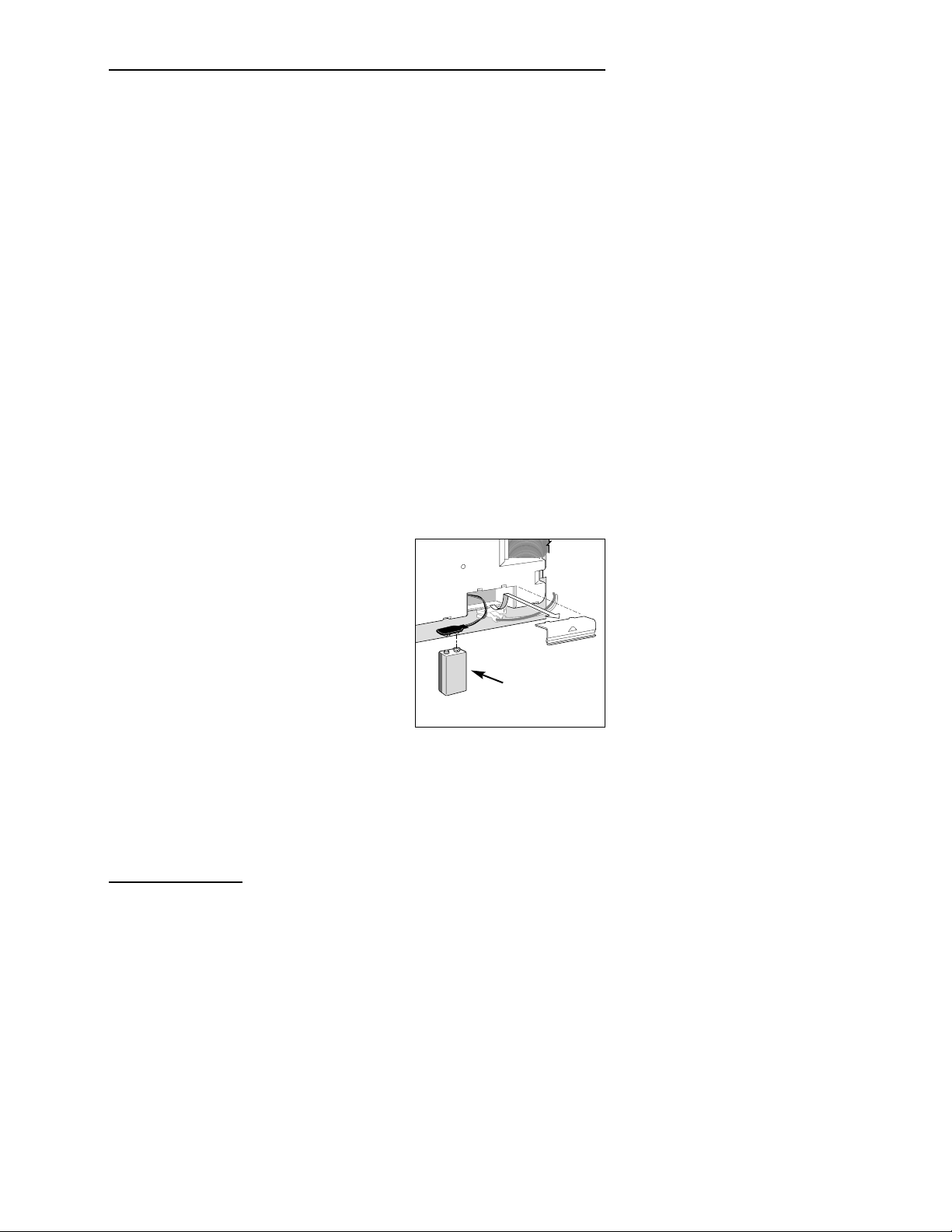
To install the battery:
1. Unlatch the hinged control module
assembly and carefully swing it
outward to open.
2. Locate and remove the battery
compartment cover from the lower
back side of the module. See Figure 3.
3. Connect a 9-volt alkaline battery to
the battery clip terminals.
4. Insert the battery into the
compartment and reinstall the battery compartment cover.
Caution: Batteries contain hazardous material. Always handle and
discard batteries properly in accordance with the battery
manufacturer’s recommendations.
GENERAL INFORMATION
General Information
Figure 3
9-Volt Alkaline
Battery
Page 7

5
General Information
HOW THE ELECTRONIC CIRCUIT
BREAKER WORKS
The controller is equipped with an electronic circuit breaker. If the
controller detects a short circuit, the affected station(s) will be turned
off automatically. The display will then flash “
SHORT” and the shorted
station number or “
MASTER VALVE.” The controller continues to
automatically water the other stations and the following watering
programs until the shorted station is repaired. The program will be
cancelled if the master valve circuit is shorted. Each automatic start
will attempt another cycle and retest the short-circuited valve.
Listed below are the most common conditions which will activate the
electronic circuit breaker. After correcting the problem,
return the
controller to normal operation as follows:
1. Set the dial to one of the following positions:
Run ,
Manual-Single Station
or
Manual-Program Cycle
.
2. Press the
OFF
button to return the controller to the normal
operating mode.
Condition: The word “SHORT” displays with one or more station
numbers.
Diagnosis: One or more stations are shorted.
Solution: Check the wiring of the displayed stations for the cause
of the shorted condition. Repair valve(s) and/or wiring
as needed.
Diagnosis: Too many valves operating at the same time causing an
overload condition.
Solution: Check watering programs for concurrent station
operation. Include master valve/pump start relay if used.
Maximum total output is 24 V a.c. at 1.25 amps. Reduce
the number of stations running at the same time.
Condition: The word “SHORT” displays without any station
numbers.
Diagnosis: A short circuit has occurred with a time duration too
short for the controller to determine the station.
Solution: Check all valve wiring for breaks in the insulation
which may cause a station output to short to common.
Diagnosis: A transient power surge spike has occurred.
Solution: Reset the controller.
Diagnosis: A short or overload occurred on one watering cycle but
was no longer there on a subsequent cycle.
Solution: Check for loose and/or exposed valve wiring.
Page 8

6
HOW THE SENSOR FEATURE WO RKS
The Total Control is equipped to operate with an optional rain
sensing device (rain switch) to prevent automatic controller operation
during rain.
The rain switch is a simple device, typically installed on a roof
overhang or stationary structure exposed to rainfall and full sun, and
shielded from irrigation spray.
When rain occurs, the normally-closed rain switch senses the moisture
and opens the valve common circuit, effectively preventing all output
to the field. The electronic programming portion of the controller is
isolated from the rain sensor switch, and continues to operate as
programmed. When rain stops and the rain switch returns to its
normally-closed state, the valve common circuit is restored, enabling
watering to resume as scheduled.
A two-position sensor switch (see item 18 on page 3) is provided to
enable you to easily bypass operation of the the rain switch at any
time. If you choose to disregard rain switch input, place the
SENSOR
switch in the
Bypass
position. To enable rain switch operation, place
the Sensor switch in the
Active
position.
IMPORTANT: If a rain switch is NOT connected to the
controller, the
SENSOR
switch MUST be in the
BYPASS
position to enable controller operation.
The controller will not operate automatically or manually if the
SENSOR
switch is in the
ACTIVE
position without a rain switch
connected.
Page 9

7
This section covers the following topics:
•
Getting started
• Setting the current time and date
• Erasing any prior programs
• Setting the station run time
• Selecting Master Valve/Pump Start on/off
• Setting the program start times
• Selecting the days to water
GETTING STARTED
PREPROGRAMMING THE CONTROLLER
The unique design of the Total Control enables you to easily remove the
control module from the cabinet for convenient programming while in the
comfort of your home.
To take advantage of this feature, unlatch the control mo dule and swing it
outward. Disconnect the ribbon cable, then simply unclip the module from
its support frame. Now, by installing a 9-volt alkaline battery (as shown on
page 4), you can program and review your watering schedules and have the
controller ready to operate immediately upon completion of the
installation procedures.
Note: To extend battery life, the display will automatically dim after two
minutes of inactivity. To restore the display, simply turn the function dial
to any position. A fresh battery will maintain the current time and date for
over 2000 hours of continuous duty. The program memory is non-volatile
and does not require a sustaining power source for retention.
WHAT IS A WATERING PROGRAM?
A watering program is basically a small set of instructions which tells the
control module when to start a watering cycle, which stations to operate
during the cycle, which days the cycle will be active and how long each
station will operate during the cycle. The Total Control has four
independent watering programs available for your use. Although only one
program is required to operate your controller, using separate programs
enables you to optimize the amount of water being applied to different
areas of the landscape. For example, you might use one program to water
lawns in full sun every day. Another program could be used to water lawns
in partial shade only on Monday, Wednesday and Friday. Trees and shrubs
PROGRAMMING THE
CONTROLLER
Programming the Controller
Page 10

8
using drip irrigation could run on a separate program once every two weeks.
The garden area requirements might include watering every other day.
To take full advantage of the programming options available, it is
important to first understand how the controller works during operation.
The following section explains what a watering cycle is and provides a
basic example of how multiple programs can be set up.
WHAT IS A PROGRAM WATERING CYCLE?
When a watering start time is selected, that time becomes the beginning
of an automatic watering cycle. A watering cycle operates each station
assigned to the program, one by one, in numerical order.
In the following example (also shown on the sample watering plan on
page 9), we have set up Program A to start at 2: 00 a.m. and again at
3:00 a.m. on a 1-day interval (every day). Stations 1, 2, 4 and 5 are front
and back yard lawn areas which get full sun throughout the day. Each
station will run for 10 minutes per watering cycle, for a total of 20
minutes run time per day. Stations 3, 6 and 7 are lawn areas which are
shaded during the afternoon hours. These areas require less water, so we
have assigned them to Program B and programmed them to run once for
20 minutes on a 2-day interval (every other day).
At 2:00 a.m., Program A watering cycle starts. Station 1 turns on, runs for
10 minutes, and shuts off. Station 2 turns on, runs for 10 minutes, and
turns off. Stations 4 and 5 operate sequentially in the same manner, each
running for their set run time. When Station 5 shuts off, the watering
cycle is completed for the first start time. At 3:00 a.m., the watering cycle
starts again and repeats the same station-by-station watering sequence.
Note that we have 40 minutes total operating time per cycle in
Program A. If we had set the next start time at 2:30 a.m., the start time
would have been delayed until 2:40 a.m., enabling the first cycle to finish
as programmed. This function is called “start time stacking”, and can
occur within each program.
Watering programs, however, operate independently, which means that
two or more programs can run simultaneously. In our example,
Program B will also start at 2:00 a.m. Therefore, Stations 1 and 3 will
turn on at the same time, and Station 2 will turn on while Station 3 is
running. This feature enables more watering to be completed within the
prime “watering window”, which is generally between Midnight and
6:00 a.m.
Note: When scheduling watering programs to run simultaneously, it is
important to ensure the water supply has sufficient pressure and volume
to maintain optimum sprinkler performance.
Programming the Controller
Page 11

WATERING SCHEDULE FORM (SAMPLE)
For your convenience, a Watering Schedule Form/Quick Reference Card
is provided. Use the form to plan and record your automatic watering
activities. Use the quick reference instructions when minor programming
changes are required. Keep the card with the controller by attaching it to
the inside front cover.
9
Programming the Controller
Station
Watering Day Schedule
Station Description
Week Days
Odd/Even
Interval
1
Watering Cycle Start Times
2
3
4
5
6
7
8
9
10
11
12
13
14
15
16
17
18
19
21
22
20
24
23
Program A Program B Program C Program D
Watering Schedule Form
Station Run Time
FFrroonntt LLaawwnn ((ssuunn)) 1100 mmiinn
FFrroonntt LLaawwnn ((ssuunn)) 1100 mmiinn
SSiiddee LLaawwnn ((sshhaaddee)) 2200 mmiinn
BBaacckk LLaawwnn ((ssuunn)) 1100 mmiinn
BBaacckk LLaawwnn ((ssuunn)) 1100 mmiinn
BBaacckk LLaawwnn ((sshhaaddee)) 2200 mmiinn
BBaacckk LLaawwnn ((sshhaaddee)) 2200 mmiinn
11
22
22 aamm,, 33 aamm
22 aamm
(Example)
Page 12

10
SETTING THE CURRENT TIME AND DATE
Before you can program the controller for automatic watering, you must
set the controller clock to the current time and date. This controller
features a 365-day calendar with automatic
leap year compensation. Once
the date is set, the controller keeps track of the
date and enables troublefree, odd-even day of the month watering required in some locations.
The time and date apply to all programs. To set the time and date, follow
the steps below.
1. Turn the Function Dial to the
Current Time & Date
position.
The Hour digits and
AM/PM
will flash.
2. Press the + button to increase or – button to decrease the hour
digit.
Note: Continuous pressure on the + or – buttons, causes the
display to change rapidly.
3. Press the
NEXT
button to select the minutes digits.
Use the + and/or – buttons to set the current minute.
4. Press the
NEXT
button to select the year digits.
Use the + and/or – buttons to set the current year.
5. Press the
NEXT
button to select the month.
Use the + and/or – buttons to set the current month.
6. Press the
NEXT
button to select the day digit(s).
Use the + and/or – buttons to set the current calendar day.
7. Return the Function Dial to the
Run
position when the current
time and date have been set.
Programming the Controller
Page 13

11
ERASING ANY PRIOR PROGRAMS
This process enables you to easily clear the controller memory of all
user-defined watering program information within an individual
program. This is an optional procedure and can be skipped if you wish
to retain previous program operating information or the controller has
not yet been programmed.
Erasing a program resets the memory to factory conditions: No station
run time, program start time or active watering days. Water Budget is
set to 100% and Master Valve/Pump Start is set to be “On.”
Note: This process is program independent and resets only the
information for the selected program.
To erase program information for a selected program:
1. Select Program
A, B, C
or Dwith the Program switch.
2. Turn the function dial to the
Program Erase
position. The display
will show “
ERASE.”
3. Press and hold the
OFF
button until “DONE” is displayed.
4. Repeat this procedure for each program you wish to erase.
SETTING THE STATION RUN TIME
A station is assigned to a program when it is given a station run time
(from 1 minute to 10 hours) in that program. The station can have only
one run time per program. Additionally, the station can be assigned to
any number of programs and have a different run time assigned in each.
To set the run time for each station:
1. Turn the function dial to the
Station Times
position. The
controller displays
STATION NUMBER 1 and OFF (or the current
station run time).
2. Select Program
A, B, C
or Dwith the Program switch.
3. Press the
NEXT
button to select the station number you wish to
set (if other than the one displayed).
4. Use the + and/or – buttons to display the desired station run time.
Note:
OFF is the factory setting for each station. If the station has a
run time and you wish to remove it from this program, use the +
and/or – buttons to select
OFF, (displayed between 10:00 [ten hours]
and
00:01 [one minute]). (CONTINUED)
Programming the Controller
Page 14

12
5. Repeat steps 3 and 4 to set a run time for each station you wish to
assign to the selected program.
6. Repeat steps 2 through 5 for each program as necessary.
MASTER VALVE/PUMP START ON/OFF
The Total Control enables automatic operation of the Master
Valve/Pump Start output circuit to be controlled independently for
each watering program. For example, if a program is used for drip
irrigation and the system pump is not required, the Master
Valve/Pump Start output circuit can be shut off whenever that
program begins operation.
The factory setting is
ON for each program. Use the steps below to
select the operation of this feature for each program as necessary.
1. Turn the function dial to the
Station Times
position.
2. Select Program
A, B, C
or Dwith the
Program
switch.
3. Press the
NEXT
button repeatedly until MASTER VALVE is
displayed.
4. Press the
OFF
or
ON
button to display the operation of the master
valve/pump start output for the selected program.
5. Repeat steps 2 through 4 for each program as necessary.
SETTING PROGRAM START TIME(S)
This procedure is used to set the watering cycle start time(s) for each
program. A maximum of 16 start times can be allocated to the four
programs in any manner. Each start time will initiate a sequential
watering cycle of all stations with an assigned run time in the program.
Note: When 16 start times have been allocated, the display will show
NONE REMAINING
when attempting to assign additional start times.
To set program cycle start time(s):
1. Turn the function dial to the
Program Start Times
position.
2. Select Program
A, B, C
or Dwith the
Program
switch.
3. Use the + and/or – buttons to display the start time.
Note: To remove a start time, adjust the time to display
OFF
(located between 11:59 p.m. and 12:00 a.m.).
4. Press the
NEXT
button to assign another start time to the
program.
5. Repeat steps 2 through 4 for each program as necessary.
Programming the Controller
Page 15

13
Note: The Total Control will operate one watering cycle in a program
at a time. If a start time occurs while a watering cycle is in progress,
the start time will be delayed until the previous cycle is finished (this
is called “start time stacking”). If the watering cycle extends past
midnight into the next day, the cycle will continue operating until
finished. However, if a watering cycle has been delayed until after
midnight into a non-watering day, the watering cycle will not occur.
SELECTING THE DAYS TO WATER
Several watering day scheduling options are available. Each watering
program can utilize any ONE of the following schedules:
• Days of the week
Use this type of schedule to water on specific days of the week. The
days are displayed as three-letter abbreviations. For example, Sunday is
SUN, Monday is
MON, etc. Only the days you select to water will
remain on the display.
• Odd Days or Even Days
To select every o dd or even number calendar day, use this option.
Because the 31st and the 1st are both odd number days, the 31st is
automatically removed from the schedule. This watering day option
also enables selected days of the week to be removed from the
schedule.
• Day Interval
Selecting watering days by Day Interval enables a specific number of
days between watering to be selected. For example, selecting a 1-day
Interval schedules watering for every day. A 2-day interval schedules
watering for every other day. A 30-day interval is the maximum
interval frequency, which provides watering once every 30 days.
Another setting within the Day Interval is the current day of the
schedule. The current day (displayed as
TODAY) can be set for any day
within the interval. This number automatically increases by one every
day. When the
TODAY number equals the Day Interval number, a
watering day will occur. For example, to water every third day starting
today, a 3-day interval would be set with
TODAY as day 3. Or, to water
every 5 days starting tomorrow, a 5-day interval would be selected with
TODAY as day 4.
Programming the Controller
Page 16

14
To set a watering day schedule for each program:
1. Turn the function dial to the
Watering Days
position. The
display will show the current watering day schedule for the
selected program.
2. Select Program
A, B, C
or Dwith the
Program
switch.
3. Set the watering day(s) for the program using one of the three
following procedures: Days of the Week, Odd Days/Even Days or
Day Interval scheduling procedure.
4. Repeat steps 2 and 3 as necessary to set a watering day schedule
for each program.
Days of the Week
A. Press the
NEXT
button until the weekday abbreviations are
shown at the top of the display.
B. Press the
ON
button. SUN (Sunday) will begin flashing.
C. To select the day, press the
ON
button. To remove the day
from the schedule, press the
OFF
button.
D. Press the
NEXT
button to select the next day.
E. Repeat steps C and D to set the remaining days of the week.
Odd Days or Even Days
A. Press the
NEXT
button until ODD DAYS or EVEN DAYS is
displayed.
B. Press the
ON
button to select the schedule.
Optional: To remove selected days of the week from the
Odd/Even watering schedule:
1. Press the
NEXT
button until the selected day begins
flashing.
2. Press the
OFF
button to exclude the day from the schedule.
(Press the
ON
button to restore the day to the schedule.)
Day Interval
A. Press the
NEXT
button until the DAY INTERVAL option is
displayed.
B. Press the
ON
button to select this option.
C. Press the
NEXT
button. The display shows the current Day
Interval number (1–30).
Programming the Controller
Page 17

15
D. Use the + or – button to select the Day Interval (1–30 days).
E. Press the
NEXT
button. The controller displays TODAY and
its current setting.
F. Use the + or – button to select the desired setting for today.
This section includes instructions for the following controller operations:
• Water Budget
• Manual Operations
• Off and Rain Delay Modes
WATER BUDGET
The Water Budget feature enables you to easily increase or decrease
the station run time (by percentage) of all
stations assigned to a
selected program. This is handy for making temporary, overall station
run time adjustments without changing the original run time settings.
Water Budget values range from 0 to 200% in 10% increments, with
100% being the normal setting.
For example, as the fall season approaches and the temperature
decreases, you may want to reduce the station time for the stations in
program A by 30%. Later you can return station times to their original
values by setting the Water Budget value back to 100%.
Note: It is possible to inadvertently cause start time stacking when
increasing station run time. Careful planning and use of Water Budget
will prevent this from occurring.
To change the Water Budget percentage value of a selected program:
1. Turn the function dial to the
Water Budget
position.
2. Select Program
A, B, C
or Dwith the
Program
switch.
3. Use the + and/or – buttons to increase or decrease the percentage
value (0–200%).
4. Turn the function dial to the
Run
position.
Note: The controller displays the % symbol in the
Run
position when Water Budget is in use for any program. During
operation, the adjusted run time will be displayed.
OPERATING THE CONTROLLER
Operating the Controller
Page 18

16
MANUAL OPERATIONS
Manual operation allows you to run individual stations or start
automatic watering programs as needed. The Total Control provides
separate dial positions for each type of operation: Single Station and
Program Cycle.
SINGLE STATION
This option enables individual stations to be operated for an untimed
duration (turned On/Off) or operated for a selectable duration from
one minute to 10 hours.
1. Turn the function dial to the
Single Station
position.
2. Select Program
A, B, C
or Dwith the
Program
switch.
Note: The programmed status of the master valve/pump start in
the selected program determines whether the master valve/pump
start will be activated with the manual operation .
3. Use one of the following options to operate the station.
For untimed operation:
A. Press the
NEXT
button as necessary to display the station you
wish to operate.
B. Press the
ON
button. The station will turn on and remain on
until one of the following occurs:
•The
OFF
button is pressed
•The controller clock passes midnight
•The function dial is moved to another position
For timed operation:
A. Press the
NEXT
button as necessary to display a station you
wish to operate.
B. Use the + and/or – buttons to set the desired amount of station
run time (for this operation only), from one minute to 10 hours.
C. To select additional stations to operate in sequence, repeat steps
A and B as desired. Each station will operate one-by-one in the
order they were selected.
D. Leave the function dial in the
Single Station
position until the
manual operation is complete, then return the dial to the
Run
position.
Operating the Controller
Page 19

17
PROGRAM CYCLE
Use this feature to manually operate watering programs. You can run the
entire program or start anywhere within the station sequence of the
program.
Note: Only the stations with an assigned run time in the program will
operate during the program watering cycle.
1. Turn the function dial to the
Program Cycle
position.
2. Select Program
A, B, C
or Dwith the
Program
switch.
3. Press the
NEXT
button to select the first station of the watering
sequence (if other than the station number displayed).
4. Press the
ON
button to start the watering cycle. Watering will start
with the selected station and will be followed by all subsequent
stations. The display will show the run time remaining for the
operating station.
Note: You may advance through the stations by pressing the
NEXT
key for the next station. To terminate operation at any time, press the
OFF
button.
5. Leave the function dial in the
Program Cycle
position until the manual
operation is complete, then return the dial to the
Run
position.
OFF AND RAIN DELAY
Use this feature to turn off controller operation for indefinite periods of time
(Off mo de) or for a selected number of days (Rain Delay mode).
Turning Off the Controller
Turning the function dial to the Off position places the controller in
the Off mode. After a 2-second delay, any current watering activity will
shut off and all subsequent watering program activity will be suspended. As
long as the function dial is in the Off position, the controller will
remain in the Off mode. The controller clock continues to update current
time and date, and all watering program information is retained while in
the Off mode. Normal controller operation is resumed by simply placing
the function dial in any other position.
Using the Rain Delay Mode
The Rain Delay mode enables automatic watering to be delayed from 1 to
7 days. At the end of the selected delay period, the controller resumes
automatic operation. (
CONTINUED)
Operating the Controller
Page 20

18
To set a Rain Delay period
1. Turn the function dial to the Rain position.
2. Use the + and/or – buttons to select the number of days (1–7) to
delay operation.
3. Turn the function dial to the Run position.
The display will show the number of days remaining in the delay
period. The day number will automatically decrease by one digit
each time the clock passes midnight. Automatic operation resumes
when the display shows no delay days remaining.
Note: The controller can be operated manually while in the Rain
Delay mode.
To cancel the Rain Delay mode:
1. Turn the function dial to the Rain position.
2. Press the – button until the display shows no delay days
remaining.
3. Turn the function dial to the Run position.
This section includes instructions for mounting the controller cabinet
and making the necessary wiring connections. To ensure safe
operation, it is important to follow the instructions carefully.
SELECTING AN INSTALLATION SITE
Selecting the proper installation site for the controller is essential to
safe and reliable operation. The outdoor model features a weather
resistant cabinet designed for indoor or outdoor installation. The
indoor model is not weather resistant and must be installed indoors
only.
The controller should be installed on a vertical wall or other sturdy
structure near a grounded power source. For outdoor models, select a
location that shades the controller during the hottest hours of the day
and provides as much protection from direct sunlight, rain, wind and
snow as possible. DO NOT mount the controller where it will be
exposed to direct spray from the irrigation system.
Operating the Controller
INSTALLATION PROCEDURES
Page 21

19
Installation Procedures
MOUNTING THE CONTROLLER
INDOOR MODEL
1. Place the mounting template (provided) on the wall, positioning
the controller display area (indicated on the template) at or
slightly below eye level. Using a small punch or nail, mark the
locations of the top and bottom centerline mounting holes and
the additional lower hole if extra cabinet support is desired.
2. Drill pilot holes at least 1-1/4" (32mm) deep into the wall using a
3/32" (2.5mm) drill for wall stud, or 1/4" (6.5mm) for masonry.
3. For the masonry wall installation only, insert plastic screw anchors
into the pilot holes.
4. Install a #10 x 1" (25.4mm) phillips-head screw into the top hole
leaving 1/4" (6mm) of the shank exposed.
5. Open the cabinet door and swing out the control mo dule by
pressing in on the release latch.
6. Using the keyhole slot, hang the controller on wall. Make sure the
screw shank slips into the top of the keyhole slot. Level the
controller and tighten the screw.
7. Install the lower screw(s).
8 Continue the wiring
installation procedures on
pages 21–23.
9. When all wiring is
complete, route the
transformer cord into the
controller and connect the
two leads to the screw
terminals marked 24 VAC.
10. Plug in the transformer
into a 120 V a.c. wall
outlet.
INSTALLATION PROCEDURES
Figure 4
Indoor Model
Page 22

20
MOUNTING THE CONTROLLER
OUTDOOR MODEL
1. Place the mounting template (provided) on the wall, positioning
the controller display area (indicated on the template) at or
slightly below eye level. Using a small punch or nail, mark the
locations of the top and bottom centerline mounting holes and
the additional lower hole if extra cabinet support is desired.
2. Drill pilot holes at least 1-1/4" (32mm) deep into the wall using a
3/32" (2.5mm) drill for wall stud, or 1/4" (6.5mm) for masonry.
3. For the masonry wall installation only, insert plastic screw anchors
into the pilot holes.
4. Open the cabinet door and swing out the control mo dule by
pressing in on the release latch.
5. With the cabinet door and control module in the open position,
turn the controller over, resting it face down on a clean smooth
work surface.
6. Using a 3/16" (5mm) drill,
carefully drill through the
center of the mounting hole
locators on the back
of the controller cabinet.
See Figure 5.
7. Align the cabinet mounting
holes with the wall pilot holes.
Using the #10 x 1" (25.4mm)
phillips head screws, securely
fasten the cabinet to the wall.
INSTALLING ELECTRICAL CONDUIT
Note: Electrical conduit and adapters are not supplied with the
controller but may be required for installation in your area. Check
local electrical codes and install conduit according to requirements.
1. For the outdoor controller power wires, install a 1/2" NPT threaded
conduit access body to the transformer assembly threaded nipple.
From the access body, install conduit to the source point of
connection. (Domestic and international models only.)
2. For field (low voltage) wiring, install a 1-1/2" (38mm) conduit
adapter and conduit.
Installation Procedures
Figure 5
Outdoor Model
Page 23

21
CONNECTING THE VALVE WIRING
1. To provide a field common wire, attach one wire to either solenoid
lead of all sprinkler valves and master valve (optional).
2. Attach a separate control wire to the remaining solenoid lead of
each valve. Label the control wires with the intended station
number for identification at the controller.
Caution: All wiring splices must be waterproofed to prevent short
circuits and corrosion.
Caution: A maximum load of 12 VA (0.5 amps) may be connected
to each station. A maximum load (including master valve) of 30 VA
(1.25 amps) may be programmed to operate simultaneously.
Exceeding these limits can damage the controller.
3. Route the control and common wires into the controller cabinet
through the bottom access opening. Remove approximately
1/2" (13mm) insulation from the ends of each wire.
4. Attach the field common wire to one of the three valve common
terminals labeled “VC.”
5. Referring to Figure 6 connect each valve control wire to the
appropriate station number terminal. If an optional master valve is
installed, connect its control wire to the terminal labeled “MV.”
Tighten all terminal screws securely.
Installation Procedures
Pump Start
Relay
or
Master Valve
Field Common
Figure 6
Valve
Sta. 3
Valve
Station 2
Valve
Station 1
ACTIVE
BYPASS
SENSOR
VALVE
TEST
24V
AC
G
N
D
SENSOR
EARTH
GND
Page 24

22
CONNECTING A PUMP START RELAY
When a pump is to be operated by the controller, a compatible relay
must be used. The relay coil will be connected to the master valve
(MV) terminal and must be rated for 24 V a.c. at 0.5A maximum. The
relay contacts will be connected to the pump start terminals and must
be rated for use with the particular pump.
Note: Transient suppressors may be needed across the relay contacts
in installations using large pumps.
Caution: Do not connect the master valve output terminal directly
to the pump start terminals. This will damage the controller.
To connect the pump start relay:
1. Connect the master valve output terminal (MV) to one side of
the relay coil.
2. Connect the other side of the relay coil to the valve common
(VC) terminal. See Figures 6 and 7.
Installation Procedures
WARNING
Proper connection of the pump and relay contacts
depends on the pump configuration and may involve
HIGH VOLTAGE. This connection should be performed by a licensed electrical contractor in
accordance with all requirements of the National
Electrical Code, applicable state and local codes and
the pump manufacturer’s recommendations.
Master Valve
(MV) Terminal
To Pump
Starter
Valve Common
(VC) Terminal
Figure 7
Page 25

23
CONNECTING A RAIN SWITCH SENSOR
The Total Control is designed for use with a normally-closed rain
sensor or “Rain Switch.” (Refer to page 6 for additional important rain
switch information.)
To connect the rain switch sensor:
1. Route the two wires from
the sensor into the cabinet
through the field wire
access opening.
2. Connect the wires to the
“
SENSOR” terminals in
either order. See Figure 8.
Note: Refer to the installation instructions provided with the
sensor for additional information.
CONNECTING AN EARTH GROUND
A power surge is a sudden rise in voltage on the power main line. It is
then often followed by a drop in voltage as the power line equipment
tries to protect area users. A lightning strike on the power grid is the
most common cause of power surges and can be damaging to the
controller. *Surge protection is built into the Total Control PC board
to reduce the potential for surge damage by shunting the voltage to
earth ground. Therefore, an important step in the installation process
is to properly connect the controller to an earth ground source,
especially if the controller is located in a lightning-prone area.
*Note: The Total Control international units are manufactured
without output surge protection. If output surge protection is required,
contact your local Irritrol Systems dealer for assistance.
Caution: The built in surge protection components cannot
effectively protect the controller circuitry from power surge unless
properly connected to an earth ground source.
To connect an earth ground:
1. Route a 12–16-gauge (2.0–1.0mm
2
) solid copper wire in the most
direct path from the “
EARTH GND” lug, located on the controller’s
terminal board (see item 21 on page 3), to an earth ground source
such as metal (not plastic) water pipe or copper-clad ground rod.
2. Clamp the bare wire securely to the pipe or ground rod. Make sure
the wire contact area is free of dirt and corrosion.
Installation Procedures
ACTIVE
Figure 8
Normally Closed
Rain Switch
Sensor
BYPASS
SENSOR
VALVE
TEST
24V
AC
G
N
D
Page 26

24
CONNECTING THE POWER WIRES
The outdoor controller has a built-in transformer which must be
connected to a grounded three-wire 120 V a.c. (domestic), 230 V a.c.
(international) or 240 V a.c. (Australia) power source.
Note: Power connection for indoor controller is discussed on page 19,
steps 9 and 10.
Caution: Do not connect the controller to one phase of a threephase power supply used by a pump or other electrical equipment.
1. Ensure the power is disconnected at the source.
2. Route the AC power and equipment ground wires through electrical
conduit to the controller.
3. Using a proper wire connection metho d, attach the Hot (Line 1)
to the Black wire, Neutral (Line 2) to the White wire and
Equipment Ground to the Green or Green/Yellow wire.
Note: The wire connection method shown in Figure 9 applies to
a domestic controller installation
only. For international controller
installation, refer to electrical
code requirements for proper wire
connection method. For
Australian installation, connect
the power cord to a grounded
240 V a.c. receptacle.
4. Close and secure the conduit
body cover. Apply power to the
controller.
WARNING
All electrical components must meet applicable national and local
electrical codes including installation by qualified personnel.
These codes may require an external junction box mounted on the
transformer nipple and a means in the fixed wiring of disconnecting
AC power having a contact separation of at least 0.120" (3mm) in
the line and neutral poles.
Ensure the AC power source is OFF prior to connecting to the
controller.
The wire used for connection to the controller must have insulation
rated at 105°C minimum.
Installation Procedures
Figure 9
Neutral To
White
Hot To
Black
Equipment
Ground To
Green
Page 27

25
❖ Error Solution
❖ All valves 1. Verify program: station time, watering start
will not times, watering days schedule, current time,
turn on current day, water budget and rain delay.
automatically
2. Check valve common wire for proper
connection.
3. Check for a shorted station; refer to
4. “How the electronic circuit breaker works”
on page 5.
5. Ensure rain sensor (if installed) is properly
connected and functioning properly. If rain
sensor is not installed, ensure the
SENSOR SWITCH is in
BYPASS position.
6. Check fuse, replace if necessary. See p. 27.
❖ Cannot 1. Disconnect power to controller for
program 1 minute. Reconnect power and reprogram.
2. Install fresh 9-volt alkaline battery.
3. Verify that all 16 start times are not in
use by other programs.
❖ Controller 1. Verify watering start times, current time
skips a cycle and watering days schedule.
❖ No display 1. Check power source for tripped circuit
breaker.
2. If program module has been removed, this
is a normal battery-saving feature. Turn dial
to any position to reactivate display.
3. Disconnect power to controller for 1 min.
Reconnect power and reprogram.
4. Replace battery
5. Check fuse, replace if necessary. See p. 27.
Troubleshooting
TROUBLESHOOTING
Page 28

26
❖ Error Solution
❖ Valve 1. Check station times and water budget.
stays on
2. Check for Manual mode; place dial in
Run
position
.
3. Disconnect valve wire. If still on, valve
malfunction is indicated.
4. Check for manual bleed closure at valve.
❖ Valve will 1 . Ensure dial is not in Rain/Off
not turn on position or Rain Delay mode active.
2. Verify program: station time, watering start
times, watering days schedule, current time,
current day and water budget.
3. Make sure common wire and valve wire are
correctly connected.
4. Check for a shorted station, refer to page 5.
5. If using sensor, check sensor.
6. Check for blown fuse. Replace if necessary.
See page 27 for fuse replacement information.
❖ “Short” or 1. See “How the Electronic Circuit Breaker
“Master Valve” Works” on page 5 for troubleshooting
is displayed information.
❖ Waters too 1. Too many program start times set. Check
often each program to determine the number of
start times assigned and remove as necessary.
Troubleshooting
Page 29

27
1. Disconnect power to the controller.
2. Carefully remove the fuse (item 17 on page 3) from the end clips.
3. Install a new 2.0A slow-blow fuse, ensuring it is securely seated in
both end clips.
4. Restore power to the controller.
Fuse Replacement
WARNING
If fuse replacement is required, replace only with the
same type and rating. Installing a higher amperage fuse
can result in serious injury and or equipment damage
due to fire hazard.
FUSE REPLACEMENT
Page 30

28
SPECIFICATIONS
Cabinet:
Outdoor – Plastic, weather-resistant, indoor/outdoor, wall mount
with key-actuated locking cover
Indoor – Durable plastic cabinet with an external transformer.
Dimensions:
Outdoor – 10.5" W x 8.375" H x 5" D
(26.67cm W x 21.27cm H x 12.7cm D)
Indoor – 9.5" W x 7.5" H x 4.25" D
(24.13cm W x 19.05cm H x 10.8cm D)
Wiring/Conduit Provision:
Power Wiring – 1/2" NPT nipple
Field Wiring – 1-1/2" (38mm) diameter conduit access
Power Specifications, Domestic Outdoor/Indoor Model:
Input – 120 V a.c., 60 Hz, 0.5A
Output – 24 V a.c., 60 Hz, 1.25A (max. total),
0.5A (max. per station)
Power Specifications, International Outdoor/Indoor Model:
Input – 230 V a.c., 50 Hz, 0.5A
Output – 24 V a.c., 50 Hz, 1.25A (max. total),
0.5A (max. per station)
Power Specifications, Australian Outdoor/Indoor Model:
Input – 240 V a.c., 50 Hz, 0.5A
Output – 24 V a.c., 50 Hz, 1.25A (max. total),
0.5A (max. per station)
Sensor Input, Outdoor/Indoor Model:
Normally-closed rain switch (override switch provided)
Master Valve/Pump Start Relay Output, Outdoor/Indoor Model:
24 V a.c., 0.5A (maximum)
Battery: 9-volt, Alkaline
Fuse: 250V, 2A, Slow-Blow
Temperature Limit Specifications:
Operating – 32°F to 140°F (0°C to 60°C)
Storage – -22°F to 149°F (-30°C to 65°C)
Specifications
Page 31

29
Notes:
Page 32

Electromagnetic Compatibility
Domestic: This equipment generates and uses radio frequency energy and if not
installed and used properly, that is, in strict accordance with the manufacturer's
instructions, may cause interference to radio and television reception. It has been
type tested and found to comply with the limits for a FCC Class B computing
device in accordance with the specifications in Subpart J of Part 15 of FCC Rules,
which are designed to provide reasonable protection against such interference in a
residential installation. However, there is no guarantee that interference will not
occur in a particular installation. If this equipment does cause interference to
radio or television reception, which can be determined by turning the equipment
off and on, the user is encouraged to try to correct the interference by one or
more of the following measures:
•Reorient the receiving antenna.
•Relocate the irrigation controller with respect to the receiver.
•Move the irrigation controller away from the receiver.
•Plug the irrigation controller into a different outlet so that the irrigation
controller and receiver are on different branch circuits.
If necessary, the user should consult the dealer or an experienced radio/television
technician for additional suggestions. The user may find the following booklet
prepared by the Federal Communications Commission helpful:
"How to Identify and Resolve Radio-TV Interference Problems." This booklet is
available from the U.S. Government Printing Office, Washington, DC 20402.
Stock No. 004-000-00345-4.
International: This is a CISPR 22 Class B product.
Technical Assistance
U.S.A.:
P.O. Box 489
Riverside, California 92502
Tel:(800) 634-8873
(909) 785-3623
Australia:
Irritrol Systems PTY Ltd.
53 Howards Road
Beverley SA 5009
Tel: (08) 8300 3633
Europe:
Irritrol Systems Europe s.p.a.
Via dell’Artigianto 1/3-Loc Prato della Corte
00065 Fiano Rome (Roma) Italy
Tel: (39) 0765 455201
© 2000 Irritrol Systems Form Number 373-0119 Rev. C
 Loading...