


MC-E |
|
|
|
|
|
|
|
|
|
|
|
|
|
|
|
|
|
|
|
|
|
|
|
|
|
|
|
|
|
|
|
|
|
|
|
|
|
|
|
|
|
|
|
||
Installation Instructions & Programming Guide |
|
||||||||||||||||||||||||||||||||||||||||||||
1 |
3 |
5 |
7 |
9 |
11 |
13 |
15 |
17 |
19 |
21 |
23 |
25 |
27 |
29 |
31 |
33 |
35 |
37 |
39 |
41 |
43 |
45 |
47 |
|
|
|
|
|
|
|
|
|
|
|
|
|
|||||||||
2 |
|
4 |
6 |
8 |
10 |
12 |
14 |
16 |
18 |
20 |
22 |
24 |
26 |
28 |
30 |
32 |
34 |
36 |
38 |
40 |
42 |
44 |
46 |
48 |
|
|
|
|
|
|
|
|
|
|
|
|
|
||||||||
|
|
|
|
|
|
|
|
|
|
|
|
1 |
|
3 |
|
5 |
|
|
7 |
|
|
9 |
|
11 |
|
13 |
15 |
|
17 |
|
19 |
21 |
23 |
25 |
27 |
29 |
31 |
33 |
35 |
37 |
39 |
41 |
VALVE |
|
|
|
|
|
|
|
|
|
|
|
|
|
|
|
|
|
|
|
|
|
|
|
|
COMMON |
|
||||||||||||||||||||||
|
|
|
|
|
|
|
|
|
|
|
|
2 |
|
4 |
|
6 |
|
|
8 |
|
10 |
|
12 |
|
14 |
16 |
|
18 |
|
20 |
22 |
24 |
26 |
28 |
30 |
32 |
34 |
36 |
38 |
40 |
42 |
VALVE |
English |
||
|
|
|
|
|
|
|
|
|
|
|
|
|
|
|
|
|
|
|
|
|
COMMON |
||||||||||||||||||||||||
|
|
|
|
|
|
|
|
|
|
|
|
|
|
|
|
|
|
|
|
|
|
|
|
|
|
|
|
|
|
|
|
|
|
|
|
|
|
|
|
|
|
|
|
|
|
For Controller Models: MC-4E, MC-6E, MC-8E, MC-12E, MC-18E, |
Español |
||||||||||||||||||||||||||||||||||||||||||||
MC-24E, MC-30E, MC-36E, MC-42E & MC-48E |
|
|
|
|
|
|
|
|
|
||||||||||||||||||||||||||||||||||||
|
|
|
|
|
|
|
|
|
|
|
|
|
|
|
|
|
|
|
|
|
|
|
|
|
|
|
|
|
|
|
|
|
|
|
|
|
|
|
|
|
|
|
|
|
Français |

Table of Contents
Introduction - - - - |
- |
- |
- |
- |
- |
- |
- |
- |
- |
- |
- |
- |
- |
- |
- |
- |
- |
- |
- |
- |
- |
- |
- |
-Pg. 3 |
Parts Diagram - - - |
- |
- |
- |
- |
- |
- |
- |
- |
- |
- |
- |
- |
- |
- |
- |
- |
- |
- |
- |
- |
- |
- |
- |
-Pg. 3 |
Cabinet Installation - |
- |
- |
- |
- |
- |
- |
- |
- |
- |
- |
- |
- |
- |
- |
- |
- |
- |
- |
- |
- |
- |
- |
- |
Pg. 4 |
Electrical Conduits Installation - |
- |
- |
- |
- |
- |
- |
- |
- |
- |
- |
- |
- |
- |
- |
- |
- |
- |
- |
Pg. 4 |
|||||
Control Wires Installation - |
- |
- |
- |
- |
- |
- |
- |
- |
- |
- |
- |
- |
- |
- |
- |
- |
- |
- |
- |
- |
Pg. 5 |
|||
Rain Sensor Installation (Purchased Separately) |
- - |
- |
-- |
- |
- |
-- |
- |
- |
-- |
- |
- |
Pg. 6 |
||||||||||||
Start Sensor Installation (Purchased Separately) |
- - |
- |
-- |
- |
- |
-- |
- |
- |
-- |
- |
- |
Pg. 6 |
||||||||||||
Power Source Installation - |
- |
- |
- |
- |
- |
- |
- |
- |
- |
- |
- |
- |
- |
- |
- |
- |
- |
- |
- |
- |
Pg. 7 |
|||
Circuit Breaker Diagnostic System - - |
- |
-- |
- |
- |
-- |
- |
- |
-- |
- |
- |
-- |
- |
- |
-- |
- |
- |
Pg. 7 |
|||||||
Power On / Reset Mode - |
- |
- |
- |
- |
- |
- |
- |
- |
- |
- |
- |
- |
- |
- |
- |
- |
- |
- |
- |
- |
- |
Pg. 8 |
||
System SETUP |
- |
- |
- |
- |
- |
- |
- |
- |
- |
- |
- |
- |
- |
- |
- |
- |
- |
- |
- |
- |
- |
- |
- |
Pg. 8 |
Current Date - - |
||||||||||||||||||||||||
Current Time - - - |
-- |
- |
- |
-- - |
- |
-- |
- |
- |
-- |
- |
- |
-- |
- |
- |
-- |
- |
- |
-- |
- |
- |
-- |
Pg. 9 |
||
Security Password - - |
- |
-- |
- - |
-- - |
- |
-- |
- |
- |
-- |
- |
- |
-- |
- |
- |
-- |
- |
- |
-- |
|
Pg. 10 |
||||
Event Days - - - |
-- |
- |
- |
-- |
- - |
-- |
- |
- |
-- |
- |
- |
-- |
- |
- |
-- |
- |
- |
-- |
- |
- |
-- |
- |
Pg. 11 |
|
Set Master Valve - |
- |
- |
- |
- |
- |
- |
- |
- |
- |
- |
- |
- |
- |
- |
- |
- |
- |
- |
- |
- |
- |
Pg. 12 |
||
Program SETUP |
|
|
|
|
|
|
|
|
|
|
|
- |
- |
- |
- |
- |
- |
- |
- |
- |
- Pgs. 13–14 |
|||
Assign Station & Runtime to a Program - |
||||||||||||||||||||||||
Program Start Time - |
- |
- |
- |
- |
- |
- |
- |
- |
- |
- |
- |
- |
- |
- |
- |
- |
- |
- |
- |
Pgs. 15–16 |
||||
Station Delay Time - |
- |
- |
- |
- |
- |
- |
- |
- |
- |
- |
- |
- |
- |
- |
- |
- |
- |
- |
- |
- |
- |
Pg. 17 |
||
Looping Start Time - |
- |
- |
- |
- |
- |
- |
- |
- |
- |
- |
- |
- |
- |
- |
- |
- |
- |
- |
- |
Pgs. 18–19 |
||||
Watering Day Schedule - |
- |
- |
- |
- |
- |
- |
- |
- |
- |
- |
- |
- |
- |
- |
- |
- |
- Pgs. 20–23 |
|||||||
Monthly Adjust / Watering Budget - - |
- |
-- |
- |
- |
-- |
- |
- |
-- |
- |
- |
-- |
- |
- |
- Pgs. 24–25 |
||||||||||
Program Review - - |
- |
- |
- |
- |
- |
- |
- |
- |
- |
- |
- |
- |
- |
- |
- |
- |
- |
- |
- |
- |
- |
- |
- |
Pg. 26 |
Program Erase |
- - - |
-- |
- - |
-- - - |
-- - - |
-- - - |
-- |
- - |
-- |
- - |
-- |
- - |
Pg. 27 |
|||||||||||
Single Program |
||||||||||||||||||||||||
Complete Program Reset - - |
- |
-- |
- |
- |
-- |
- |
- |
-- |
- |
- |
-- |
- |
- |
-- |
- |
- |
-- |
- |
Pg. 28 |
|||||
Complete Controller Reset - |
- |
- |
- |
- |
- |
- |
- |
- |
- |
- |
- |
- |
- |
- |
- |
- |
- |
Pg. 28 |
||||||
Station Test - - - - |
- |
- |
- |
- |
- |
- |
- |
- |
- |
- |
- |
- |
- |
- |
- |
- |
- |
- |
- |
- |
- |
- |
- |
Pg. 29 |
Options |
- |
- |
- |
- |
- |
- |
- |
- |
- |
- |
- |
- |
- |
- |
- |
- |
- |
- |
- |
- |
- |
- |
- |
Pg. 30 |
Options 1–8 - - |
||||||||||||||||||||||||
Option 9- - - - |
- |
- |
- |
- |
- |
- |
- |
- |
- |
- |
- |
- |
- |
- |
- |
- |
- |
- |
- |
- |
- |
- |
- |
Pg. 30 |
Option 10 - - - |
- |
- |
- |
- |
- |
- |
- |
- |
- |
- |
- |
- |
- |
- |
- |
- |
- |
- |
- |
- |
- |
- |
- |
Pg. 31 |
Option 11 - - - |
- |
- |
- |
- |
- |
- |
- |
- |
- |
- |
- |
- |
- |
- |
- |
- |
- |
- |
- |
- |
- |
- |
- |
Pg. 31 |
Rain Off - - - -- - - -- - |
- |
-- |
- |
- |
-- |
- |
- |
-- |
- |
- |
-- |
- |
- |
-- |
- |
- |
-- |
- |
- |
-- |
- |
Pg. 32 |
||
Semi-Auto Operation - |
- |
- |
- |
- |
- |
- |
- |
- |
- |
- |
- |
- |
- |
- |
- |
- |
- |
- |
- |
- |
- |
Pg. 32 |
||
Manual Operation - - - |
-- |
- |
- |
-- - - |
-- |
- |
- |
-- |
- |
- |
-- |
- |
- |
-- |
- |
- |
-- |
- |
- |
- |
Pg. 33 |
|||
Remote Control (Purchased Separately) |
- |
- |
- |
- |
- |
- |
- |
- |
- |
- |
- |
- |
- |
- |
- |
Pg. 34 |
||||||||
Flow Sensor - - - - - |
- |
- |
- |
- |
- |
- |
- |
- |
- |
- |
- |
- |
- |
- |
- |
- |
- |
- |
- |
- |
Pgs. 35–39 |
|||
Specifications - - - -- - - |
-- - - |
-- - |
- |
-- - |
- |
-- - |
- |
-- |
- |
- |
-- |
- |
- |
Back Cover |
||||||||||
Electromagnetic Compatibility - |
- |
- |
- |
- |
- |
- |
- |
- |
- |
- |
- |
- |
- |
- |
- |
Back Cover |
||||||||
Introduction
Thank you for purchasing the MC-E controller by Irritrol. The MC-E controller is a solid-state irrigation controller, capable of storing eight independent programs designed to meet the needs of commercial and contractor applications. The MC-E is an enhancement to the existing MC controller with many more functions and display features. The new MC-E is designed to be compatible with the previous MC Plus B cabinets and wiring connections.
|
|
|
|
|
|
|
|
Parts Diagram |
|
|
|
|
|
|
1 |
|
|
|
|
|
- |
Use to navigate through the menu options |
|
|
|
|
|
|
|
|
|
|
|||
|
BACK |
NEXT |
|
|
1 |
2 |
MC-12E |
- |
Use to navigate through the menu selections |
||
|
LEFT |
RIGHT |
UP |
DOWN |
3 |
ENTER |
|||||
|
LIGHT |
|
|
|
SUN |
MON |
TUE |
|
|
or options |
|
|
BACK |
|
|
|
4 |
5 |
6 WATERTIME |
|
|
||
|
|
|
|
|
|
|
|||||
|
|
|
PROGRAM MASTER |
WED |
THU |
FRI |
|
- |
Use to navigate through the menu selections |
||
|
|
|
SAT |
|
|
|
|||||
|
MANUAL |
AUTO |
RUN |
|
7 |
|
|
|
|
|
|
|
|
SETUP |
POWER |
8 |
9 |
CYCLE |
|
|
|||
2 |
RAIN OFF |
|
SET |
|
START |
|
or options |
||||
STATION |
|
REMOTE |
FLOW |
ON/OFF |
0 |
OFF |
ON |
|
|||
|
OPTIONS |
|
PROGRAM VALVE |
|
|
|
|
|
|
||
|
|
|
REVIEW |
|
MANUAL |
|
DAY |
DAY |
|
|
|
|
TEST |
|
CONTROL |
ALARM |
|
|
% CLEAR |
|
|
||
|
PROGRAM |
|
MONTHLY |
|
SET |
SET |
- |
Finalize and save entered parameters |
|||
|
ERASE |
4 5 |
ADJUST |
11 12 |
TIME |
DATE |
|||||
|
1 2 3 |
6 7 8 9 10 |
|
|
PM |
|
|||||
|
|
FLOW |
SENSING |
|
|
|
|
|
|
|
|
|
STATIONS |
|
|
|
|
|
|
|
|
|
|
|
|
|
|
|
|
|
|
|
- |
SETUP - Assigns Station and Station |
|
|
3 |
|
4 |
|
5 |
|
6 |
7 |
|
Runtime to a program |
|
1 - 32-Character Dot Matrix LCD |
|
|
- SETUP - Assign Start Times to a program |
||||||||
2 - Timing Mechanism Quick Release |
- SETUP - Assign Event Days |
||||||||||
3 - Active Station Indicator Display |
|
- SETUP - Remove Event Days |
|||||||||
4 - |
Function Dial |
|
|
|
|
|
- MANUAL - Activate stations or programs |
||||
5 - Flow Alarm Indicator LED |
|
|
|
|
manually |
||||||
|
|
|
- SETUP / SET PROGRAM - Modify the |
||||||||
6 - Master Valve Active Indicator LED |
|||||||||||
|
current time |
||||||||||
7 - |
Power Supply Indicator LED |
|
|
- SETUP / SET PROGRAM - Modify current |
|||||||
- |
Activates the LCD Display Backlight |
|
date |
||||||||
- MONTHLY ADJUST - Adjust water budget |
|||||||||||
- |
Use to navigate through the menu options |
||||||||||
|
percentage. |
||||||||||
|
|
|
|
|
|
|
|
|
- |
Clear / Delete selection / Revert back to the |
|
|
|
|
|
|
|
|
|
|
|
main menu of the current dial position |
|
|
|
|
|
|
|
|
|
|
|
|
|

|
|
Cabinet Installation |
|
|
|
|
|
|
|
|
|
|
|
|
|
|
Step 1 – |
Selecting the proper installation site for the MC-E controller is |
|
|
|
|
|
|
Figure 1 |
|
|
|
|||
|
|
essential to safe and reliable operation. The controller features |
|
|
|
|
|
|
|
|
|
|
|
|
|
|
|
a weather resistant cabinet designed for indoor and outdoor |
|
|
|
|
|
|
|
installation. The controller should be installed on a vertical wall |
|
|
|
|
|
|
|
or other sturdy structure near a grounded power source. Select a |
|
|
|
|
|
|
|
location that provides as much protection from direct sunlight, |
|
|
|
|
|
|
|
rain, snow and irrigation spray as possible. |
|
|
|
|
|
|
Step 2 – |
Drive a wood screw (provided) into the wall at eye level. |
|
|
|
|
|
|
|
(For Large Cabinet Unit - 18 Stations or more) Drive another |
|
|
|
|
|
|
|
wood screw 8” (20.3 cm) directly below the first screw. |
|
|
|
|
|
|
|
(For Small Cabinet Unit - 12 Stations or less) Drive another wood |
|
|
|
|
|
|
|
screw 5 3/4” (14.5 cm) directly below the first screw. |
|
|
|
|
|
Leave approximately 1/4” (6.5 mm) of the screw extended from the wall to accommodate the cabinet.
For drywall and masonry installation, use proper screw anchors to prevent the screws from loosening.
Step 3 – Place the controller cabinet on the screws using the keyhole slots on the back panel. Ensure that the cabinet is installed securely on the screws. See Figure 1.
Step 4 – Open the controller door and remove the bottom panel door. Locate the bottom screw and tighten it securely.
The MC-E series has two available lockable, weather and vandal resistant steel pedestals for free standing applications. For MC-E controllers with 12 stations or less, use the Irritrol P-2B pedestal. For MC-E controllers with 18 stations or more, use the Irritrol P-6B pedestal. Follow the installation and mounting instructions that are provided with the pedestal.
Electrical Conduit Installation
Electrical conduit and adapters are not supplied with the controller but may be required for installations in your area. Check with your local electrical codes and install conduit according to requirements.
For power wires, install a 1/2” (13 mm) NPT threaded conduit access body to the transformer assembly threaded nipple. From the access body, install conduit to the power source.
For station valve wiring, install a 2” (5 cm) conduit adapter and conduit.

Control Wires Installation
Step 1 – Route the valve control wires between the valves and the MC-E controller.
For wire runs up to 1000’ between the controller and the valves, it is recommended to use an 18 AWG |
||||||||||||||||||||||||
(1.0 mm2) multi-wire sprinkler valve connection cable. This cable is insulated for direct burial and is color |
||||||||||||||||||||||||
coded to simplify installation. |
Figure 2 |
|
|
|
|
|
|
|
|
|
|
|
|
|
|
|
|
|
|
|
|
|
||
Step 2 – Attach one wire from each valve solenoid to |
|
|
|
|
|
|
|
|
|
|
|
|
|
|
|
|
|
|
|
|
|
|||
Wiring for standard (non-flow sensing) system |
||||||||||||||||||||||||
the white color-coded wire from the cable. |
||||||||||||||||||||||||
(Since the valve solenoid has no polarity, either |
|
|
|
|
|
|
|
|
|
|
|
|
|
|
|
|
|
|
|
|
|
|
|
|
wire can be used for this connection.) Designate |
YEL RED GND |
1 |
3 |
5 |
7 |
9 |
11 |
13 |
15 |
17 |
19 |
21 |
23 |
25 |
27 |
29 |
31 |
33 |
35 |
37 |
39 |
41 |
VALVE |
|
COMMON |
||||||||||||||||||||||||
|
||||||||||||||||||||||||
this connection as the Valve Common. |
|
|
|
|
|
|
|
|
|
|
|
|
|
|
|
|
|
|
|
|
|
|
|
|
|
VALVE VALVE MASTER |
2 |
4 |
6 |
8 |
10 |
12 |
14 |
16 |
18 |
20 |
22 |
24 |
26 |
28 |
30 |
32 |
34 |
36 |
38 |
40 |
42 |
VALVE |
|
Step 3 – Attach a separate cable wire to each of the |
COMMON COMMON VALVE |
COMMON |
||||||||||||||||||||||
|
|
|
|
|
|
|
|
|
|
|
|
|
|
|
|
|
|
|
|
|
|
|
||
remaining valve solenoid wire. Take note of the |
|
|
|
|
|
|
|
|
|
|
|
|
|
|
|
|
|
|
|
|
|
|
|
|
wire color being used for each valve as well |
|
|
|
|
|
|
|
|
|
|
|
|
|
|
|
|
|
|
|
|
|
|
|
|
as the watering zone/area it is designated. This |
|
|
|
|
|
|
|
|
|
|
|
|
|
|
|
|
|
|
|
|
|
|
|
|
information will be important when connecting |
|
|
|
|
|
|
|
|
|
|
|
|
|
|
|
|
|
|
|
|
|
|
|
|
the valve wires to the controller’s station |
|
|
|
|
|
|
|
|
|
|
|
|
|
|
|
|
|
|
|
|
|
|
|
|
terminals. |
|
|
|
|
|
|
|
|
|
|
|
Station 1 |
|
*Station 2 |
|
Station 3 |
||||||||
Step 4 – Use wire nut fasteners to secure the valve |
|
|
|
|
|
|
|
|
|
|
|
|
|
|||||||||||
|
|
|
|
|
|
|
|
|
|
|
|
|
|
|
|
|
|
|
|
|
|
|
||
solenoid wire connection. Waterproof all |
Master |
|
|
Pump Start |
|
|
|
|
|
|
|
|
|
|
|
|
|
|||||||
connections with grease caps or similar |
* Valve |
|
|
|
Relay |
|
|
|
|
|
|
|
|
|
|
|
|
|
|
|||||
insulation method. |
|
|
|
|
|
|
|
|
|
|
|
|
|
|
|
|
|
|
|
|
|
|
|
|
Step 5 – Route the other end of the control wires into the |
|
|
|
|
|
|
|
|
|
|
|
|
|
|
|
|
|
|
|
|
|
|
|
|
provided conduit hole at the bottom of the cabinet. Leave about 8” of cable remaining in the cabinet. Expose |
||||||||||||||||||||||||
about 3/8” of bare wire from the station and the valve common wires. |
|
|
|
|
|
|
|
|
|
|
|
|
|
|
|
|
|
|||||||
Step 6 – Secure the valve common wire to one of the three terminals labeled “VALVE COMMON” and each valve wire |
|
|
to its appropriate station terminal designation. |
* |
For flow monitoring, with a flow sensor installed, Station #2 is programmed and used as activation circuit for |
|
a normally-open master valve instead of a regular station valve. (See page 36 “Install Critical Flow Shut Off |
|
Master Valve”.) |

Rain Sensor Installation (Purchased Separately)
IMPORTANT! The INHIBIT SENSOR is designed for a normally closed rain sensor. The wire jumper must be present at the terminals if a sensor is not connected.
Step 1 – Route the rain sensor cable into the controller terminals.
Step 2 – Remove the wire jumper from the INHIBIT and SENSOR terminals for the 18 stations or more models and INHIB.SEN and SEN.COM for the 12 stations or less models. Refer to the provided rain sensor installation guide for wiring instructions and connect accordingly.
The INHIBIT SENSOR will operate on any Function Dial position settings.
2 |
4 |
6 |
8 |
10 |
12 |
14 |
16 |
18 |
20 |
22 |
24 |
26 |
28 |
30 |
32 |
|||
|
|
|
|
|
|
|
|
|
|
|
|
|
|
|
|
|
|
|
|
|
|
|
|
|
|
|
|
|
|
|
|
|
|
|
|
|
|
|
|
|
|
|
|
|
|
|
|
|
|
|
|
|
|
|
|
|
|
|
|
|
|
|
|
|
|
|
|
|
|
|
|
|
|
|
|
|
|
|
|
|
|
|
|
|
|
|
|
|
|
|
|
|
|
|
START SENSOR |
FLOW SENSOR |
|
|
|
|
|
|
|
YEL |
RED |
GND |
1 |
3 |
5 |
7 |
VALVE VALVE |
MASTER |
2 4 6 8 |
COMMON COMMON |
VALVE |
Start Sensor Installation (Purchased Separately)
IMPORTANT! The START SENSOR input is designed for a normally open sensor and works in conjunction with Options 9
and 10. When the start sensor is activated, the MC-E controller will immediately activate Program 1 providing Option 10 is activated. Program 1 will continue to repeat the cycle until the start sensor is deactivated. The activation of the start sensor will not affect any other programs. Option 9 works similarly by turning ON program 8, however all other programs are turned OFF.
Step 1 – Route the sensor connection cable through the bottom of the controller cabinet and into the controller terminals.
Step 2 – Refer to the provided sensor installation guide for wiring instructions.
The START SENSOR will operate on any Function Dial position except for RAIN OFF.
1 |
3 |
5 |
7 |
9 |
11 |
13 |
15 |
17 |
19 |
21 |
23 |
25 |
27 |
29 |
31 |
33 |
35 |
37 |
39 |
|||||||
2 |
|
4 |
6 |
8 |
10 |
12 |
14 |
16 |
18 |
20 |
|
22 |
24 |
26 |
28 |
30 |
32 |
34 |
36 |
38 |
||||||
|
|
|
|
|
|
|
|
|
|
|
|
|
|
|
|
|
|
|
|
|
|
|
|
|
|
|
|
|
|
|
|
|
|
|
|
|
|
|
|
|
|
|
|
|
|
|
|
|
|
|
|
|
|
|
|
|
|
|
|
|
|
|
|
|
|
|
|
|
|
|
|
|
|
|
|
|
|
|
|
|
|
|
|
|
|
|
|
|
|
|
|
|
|
|
|
|
|
|
|
|
|
|
|
|
|
|
|
|
|
|
|
|
|
|
|
|
|
|
|
|
|
|
|
|
|
|
|
|
|
|
|
|
|
|
FLOW SENSOR |
|
|
|
|
|
|
|
|
|
YEL |
RED |
GND |
1 |
3 |
5 |
7 |
9 |
11 |
1 |
|
|
|
|
|
|
|
|
|
|
|
|
|
|
|
|
|
|
|
VALVE VALVE |
|
MASTER |
2 4 6 8 10 12 1 |
|||||||||||||||
COMMON COMMON |
|
VALVE |
||||||||||||||||
SEN.COM START SEN.
 Models with 12 Stations or Less
START SENSOR
 Models with 18 Stations or More
Power Source Installation
 WARNING: All electrical components and installation practices must meet applicable national and local electrical codes including installation by a qualified personnel. These codes may require an external junction box mounted on the cabinet and a circuit breaker in the main wiring having a contact separation of at least 0.120” in the line and neutral poles.
The 120 VAC power source must be turned OFF prior to servicing. The power cable used for connection to the controller must have an insulation rating of 221° F minimum.
Step 1 – For power source connection, install a 1/2” electrical conduit from the 120 VAC power source to the MC-E controller cabinet.
Step 2 – Install an electrical junction box at the transformer to allow access for future servicing.
Step 3 – Confirm that power has been disconnected at the power source using a volt meter or voltage detector.
Step 4 – Route 14-AWG insulated solid copper wires for Power (Black), Neutral (White) and Equipment Ground (Green) through the conduit and into the junction box.
Step 5 – Strip back 3/8” of insulation from each wire. Using wire
connectors, connect the wires with similar colors together (Black with Black, White with White, etc.).
Step 6 – Tuck the wires inside the junction box and replace the cover.
Step 7 – Apply power to the controller.
Circuit Breaker Diagnostic System
The controller’s system for managing an electrical short circuit is designed to isolate the station with the problem and continue to water operable stations. The sequence the controller follows is listed below.
1.The controller reaches a station with a short circuit.
2.The controller shuts off the problem station and skips to the next station in the same program and continues operation.
3.The controller displays “Fuse Alarm on __” and the problem station’s number as well as the other station in operation.
4.In between programs, when the controller is idle, it will display the Fuse Alarm station alternating with the display of Day/Date/Time.
5.The next time the controller is supposed to run the station, it will try again. If the cause of the short has been repaired, the Fuse Alarm will disappear from the display and the station will run normally. You can also use the CLEAR button to clear the Fuse Alarm from the display. This does not fix the shorted circuit, but only clears its display.
The controller has fractions of a second to detect and shutoff the problem station before the short circuit causes damage. On occasion, with multiple programs and stations running, the controller shuts off and displays two stations as having shorts. You can test each station in MANUAL mode or with STATION TEST to find the shorted one.
Power On / Reset Mode
MC-E will initiate the operating system and reload all saved data in the memory for stable operation every time the |
|
controller is powered up. Place the Function Dial in the Auto/Run position for normal operation. |
|
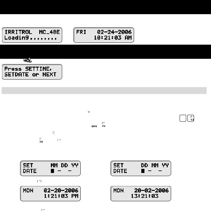
Initial Display |
Auto Run Mode Display |
|
System SETUP |
|
The SETUP |
function allows you to modify the following MC-E parameters: |
|
|
• Current Date |
• Current Time |
|
• Security Password |
• Event Days |
• Enable/Disable Master Valve
SETUP – Current Date
Set Current Date
Step 1 – Place the Function dial to the SETUP 

 position.
Step 2 – Set the date mode if necessary. To set the date to International format (Day/Month/Year), press 


 . To return to the default U.S. format, press
 .
.
 Press the
  button to clear any “Key Entry Error”. Step 3 – Press the
  or the
  button to access the date setup screen.
Step 4 – Enter the Month, Date and Year in MM DD YY format. If the MC-E is operating in International format, enter the Date first, the Month second and the year last (DD MM YY).
Example: For February 20, 2006, press the 022006 buttons.
U.S. format
Step 5 – Press the  button to accept the changes. The display will now reflect the new date.
U.S. format
 While in SET DATE mode, you can advance to the SET TIME mode by pressing the NEXT
  button.
Step 6 – Return the Function dial to AUTO/RUN  position to exit SETUP.
International format
International format

SETUP – Current Time
Set Current Time
Step 1 – Place the Function Dial to the SETUP 

 position.
Step 2 – Set the time mode if necessary. To set the time to International format (24-hour), press 


 . To return to the default U.S. format, press
 .
.
|
Press the |
button to clear any “Key Entry Error”. |
|
Step 3 – Press |
or press the |
button until the time setup screen is displayed. |
|
|
|
U.S. format |
International format |
Step 4 – Enter the Hour, Minutes and Seconds in H MM format. Enter the H MM  for PM time. International setting follows the 24-hour format.
Example: For 10:30am, enter 1030.
Step 5 – Press the  button to accept the changes. The display will now reflect the new time.
U.S. format |
International format |
 While in SET TIME mode, you can advance to the SET LANGUAGE screen by pressing the NEXT
 button or go back to SET DATE by pressing the BACK
  button. Step 6 – Return the Function dial to AUTO/RUN
  position to exit SETUP.

SETUP – Security Password
The MC-E can be secured with a security password to ensure that unauthorized users are not able to modify the programs.
Enable Security Password
Step 1 – Place the Function Dial to the SETUP 

 position.
Step 2 – Press the  button. The screen will display the following:
Step 3 – Enter a four-digit (0000–9999) security password and press the  button.
Once a security password is established, all menu functions will require you to enter the four-digit security password before gaining access. However, manual operations are allowed.
Once the security password is verified, the MC-E will allow access to the menu functions for one hour. Within that hour, you will be able to navigate through all the function dial positions without re-entering the security password. After the 1-hour time limit expires, you will need to re-enter the password to gain access to the menu functions.
In the event that you have forgotten the four-digit security password, press 
 ,
, 


 ,
, 


 and
and 


 to disable the password verification process. To reestablish password security to the controller, you must repeat Steps
1–3.
 Press the
  button to clear any “Key Entry Error”.
Step 4 – Return the Function dial to AUTO/RUN  position to exit SETUP.
10
SETUP – Event Days
The MC-E allows you to pre-program ten event days throughout the year. During an event day, the controller will suspend automatic watering. Event days will reoccur every year unless deleted.
Example: If July 4th is set as an event day, the controller will ignore watering every July 4th of each year until it is deleted from the Event Days.
Set Event Day:
Step 1 – Place the Function Dial to the SETUP 

 position.
Step 2 – Press the  button. The screen will display the following:
Press the  button to review the day off events or enter new events. The screen will display the following:
Use the |
or |
button to review the programmed events. Press the |
button to clear any “Key |
Entry Error”. |
|
|
|
Step 3 – Enter the Event number (1–10), then press the  button.
 MC-E will re-number the event day if the newly created event is deleted.
Step 4 – Enter the Month and Date (MM DD) of the event day being programmed and press the 


 button. When the controller is in International mode, enter the Date first before the Month (DD MM). The controller will increment the total event day and display the following:
Step 5 – Repeat Steps 2–3 for additional event days.
Step 6 – To delete an event, scroll through the event number to select it. Once the event is displayed, enter 


 and press the
  button to delete.
Step 7 – Return the Function dial to AUTO/RUN  position to exit SETUP.
11

SETUP – Master Valve
Set Master Valve
As factory default, the Master valve is Enabled for all stations. The master valve will activate whenever a station is activated.
 If flow sensing is to be activated, all stations must be set to “MV=ON”.
In situations that a station does not require the master valve to activate, use the following procedure to select the station and Disable or Enable the master valve.
Step 1 – Place the Function Dial to the SETUP 

 position.
Step 2 – Press the  button. The following display will be shown on the screen.
Step 3 – |
Press the |
or |
buttons to select the station number you want to edit. Use the |
or |
button to |
|
toggle MV (Master Valve) from ON or OFF. |
|
|
||
|
Press the |
button to clear any “Key Entry Error”. |
|
|
|
Step 4 – |
Repeat Step 3 for additional stations. |
|
|
||
Step 5 – Return the Function dial to AUTO/RUN  position to exit SETUP.
12
 Loading...