


 Get more doneTM
Junior Max (JR Max™)
Controller
stations
Operating Instructions

Thank you for purchasing this advanced, highly featured Irritrol Junior MAX controller. The Junior MAX is the latest addition to the Irritrol Junior Series.
The Junior Plus, Junior DC and now the Junior MAX make this the most versatile, highly featured and economical controller series on the market today.
The following pages will describe the features of the Junior MAX and give you clear directions for using them and getting the most out of your new controller.
We at Irritrol are confident that you will be impressed with the power of
the Junior MAX and pleased with its quality and value. If you have any suggestions for other control features that you’d like to see in one of our controllers or a future product, please write to us at Irritrol. We’d love to hear from you!
Irritrol Irrigation Systems |
|
|
International Product Manager |
|
|
5825 Jasmine Street |
|
|
Riverside, CA 92504 U.S.A. |
|
|
______________________________________________________ |
||
About the Junior MAX memory |
|
|
This controller is equipped with "on board" back up battery that will keep the program |
||
memory for a few years in case power is not available. If you wish to program the |
||
controller without connecting it to AC power, install the 9 volt alkaline battery. The 9 volt |
||
battery will turn on the display. To turn on the programming guide light, press one of the |
||
keys. (any key) The programming guide light will turn off after 10 seconds if no key is |
||
pressed. |
|
|
Automatic Circuit Breaker |
|
|
The Junior MAX controller is equipped with an automatic circuit breaker making fuse |
||
replacement a thing of the past. A short circuit in the field wiring or the valve solenoid |
||
will cause the automatic circuit breaker open and stop electrical output. The “24V” will |
||
flash and the red “AUTO” light will blink. If the fault isn’t corrected by the next start |
||
time, the controller will initiate another watering cycle and advance through the set |
||
stations until it encounters the station with the electrical fault. The program will again |
||
terminate and display the blinking “24V” icon and the blinking red “AUTO” light. To |
||
verify that there is a short circuit problem, go to the manual mode and start the station. If it |
||
doesn’t start or turns off before the set run time, troubleshoot the field wiring and valve |
||
solenoid. |
|
|
Power failure indication |
|
|
During a power failure the “24V” will start flashing, if a 9 volt battery is connected. |
||
"24V" will stop flashing as soon as power resumes. |
Station Output Power: |
|
Electrical Specifications: |
|
24 VAC |
Input power: |
|
6 VA (0.25 amps) |
120 VAC, 50/60 Hz (Plug-in transformer, CUL approved) |
per station maximum |
|
230 VAC, 50/60 Hz (Plug-in transformer, CE Mark) |
6 VA (0.25 amps) |
|
240 VAC, 50/60 Hz (Plug-in transformer, SAA) |
pump start/master valve |
|
18 W (0.75 amps) maximum |
2 |
12 VA (0.50 amps) total load |

INSTALLATION INSTRUCTIONS - INDOOR MODELS:
Su Mo Tu We Th Fr |
Sa |
AUTO |
|
|
|||
Year |
System off |
Set Time/Day |
|
Semi-Auto |
Run Times |
||
Month |
|||
Day |
|
|
|
Time |
Manual |
Water Days |
|
Station |
% Scaling |
Start Time |
|
Start |
|
Programming guide light
LCD INLAY -
To place or replace look at instruction inside the plastic bag.
9 volt
battery drawer
Reset electronic fuse
TRANSFORMER
RESET 
SENSOR |
install in a protected area.
Master
Valve
c o m m o n t o a l l v a l v e s
Remove the lower cover. Place the unit on the wall using the top screw slot. Level the controller, then insert screw into the lower screw hole under the terminal block.
Connect the solenoid wires to the terminal block. Connect one wire from the solenoid to its respective station number on the terminal block and the other wire to the C-common terminal. Connect the transformer wires to the 24 VAC terminal.
Note: A 9 VDC battery must be installed for proper operation of the controller. The 9 volt battery compartment is located on the right side of the case. It is marked “Push”. Push it to release the battery drawer. The 9 volt battery powers the LCD display in the absence of AC power and allows “Arm Chair Programming”. Program information is retained during power outages by an on-board lithium battery.
NOTE: Only after all the wiring is completed and checked should the transformer be
plugged into AC power. |
3 |
|
INSTALLATION INSTRUCTIONS - OUTDOOR MODELS:
Remove the lower cover of the Junior Max controller by sliding it down. Place the unit on the wall using the top keyhole screw slot. Level the controller and then insert screws into one or more of the three lower screws holes at the cabinet bottom. Drive the screws through the plastic flashing that keep the cabinet weather resistant. If installing the controller on drywall or masonry, install screw anchors to prevent the screws from loosening. Connect the solenoid wires to the terminal block through the 12mm (1/2”) hole in the right side of the cabinet bottom. If the solenoid wires are being installed in conduit, there is a knock-out on this hole that will accept a 24mm (1”) male conduit adapter. Connect the wires as shown for the indoor model. Next connect the power wires.
 Warning: AC power wiring must be installed and connected by qualified personnel only. All electrical components and installation procedures must comply with all local and national electrical codes. Some codes may require a means of disconnection from the AC power source installed in the fixed wiring and having a contact separation of at least 3mm (0.120”) in the line and neutral poles.
Make sure the power is OFF prior to connecting the controller.
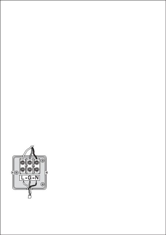
The hole on the left side of the cabinet bottom accepts a 12mm (1/2”) male conduit adapter. Route the power and equipment ground wires from the power source, through the conduit and into the transformer connector compartment. Note: The terminal block accepts wire size up to 4mm2 (12 AWG). Remove 10mm (3/8”) of insulation from the wire ends.
Using a small flat bladed screwdriver, secure the wires as follows: Line or Line 1 (L1) to L, Neutral or Line 2 (L2) to N and Equipment Ground to G. Install compartment cover. Apply power to the controller.
9 VDC Battery. The 9 volt battery compartment is located below the 24VAC terminals. The 9 volt battery powers the LCD display in the absence of AC power and allows programming without AC power. Program information is retained during power outages
by an on-board lithium battery.
4
 Loading...