


TM
Automatic Sprinkler System Controller
User’s Guide
KwikDial Features:
• Three Independent Watering Programs
•Watering Schedule by 7-Day Calendar, Day Interval or Odd/Even Days
•Three Start Times Per Program
• Multi-language Display Option
•24-hour Memory Back-up Without Battery
•Automatic Valve Testing Mode
•Rain Delay Mode
•Remote Control Ready
•Rain Sensor Ready
Outdoor Model
Indoor Model
ais Franç ol Españ English

Specifications
Dimensions - Indoor Models
6" W x 9" H x 3" D
(15.3 cm W x 22.9 cm H x 7.6 cm D)
Dimensions - Outdoor Models
6" W x 9" H x 4" D
(15.3 cm W x 22.9 cm H x 10.2 cm D)
Power Specifications: Indoor Models - Domestic
Plug-in Transformer, Class 2, UL Listed, CSA Certified (or equivalent)
•Input: 120 V a.c. 50/60 Hz, 0.5 Amps
•Output: 24 V a.c. 50/60 Hz, 20 VA
Outdoor Models - Domestic
Built-in Transformer, Class 2, UL Listed, CSA Certified (or equivalent)
•Input: 120 V a.c. 50/60 Hz, 0.5 Amps
•Output: 24 V a.c. 50/60 Hz, 20 VA
Indoor Models - Export
Plug-in Transformer, TUV Approved
•Input: 230 V a.c. 50 Hz, 0.1 Amps
•Output: 24 V a.c. 50 Hz, 20 VA
Outdoor Models - Export
Built-in Transformer, TUV Approved, SAA Approved
•Input: 230/240 V a.c. 50/60 Hz, 0.1 Amps
•Output: 24 V a.c. 50/60 Hz, 20 VA
Indoor Models - Australia
Plug-in Transformer, SAA Approved
i
• Input: 240 V a.c. 50 Hz, 0.1 Amps
• Output: 24 V a.c. 50 Hz, 20 VA
Maximum Load Per Station:
0.4 Amps @ 24 V a.c.
Maximum Load For Pump/Master Valve:
0.4 Amps @ 24 V a.c.
Total Maximum Output: One station plus pump, not to exceed 0.80 Amps @ 24 V a.c.
Temperature Limit Range:
Operating – 14°F to 140°F (-10°C to 60°C) Storage – -22°F to 149°F (-30°C to 65°C)

Table of Contents |
|
KwikDial Components..................................... |
2–3 |
Controller Installation ...................................... |
4–7 |
• Installing the Cabinet ........................................ |
4 |
• Connecting the Valves.................................. |
4–5 |
• Connecting a Pump Start Relay ....................... |
5 |
• Rain Switch Sensor Installation ....................... |
6 |
• Connecting the Power Source...................... |
6–7 |
Programming ................................................... |
8–13 |
• Setting the Date/Time....................................... |
8 |
• Planning Your Watering Schedule.................... |
8 |
• Watering Schedule Form............................ |
9–10 |
• About the KwikDial Memory ............................ |
11 |
• Setting a Calendar Day Schedule ................... |
11 |
• Setting an Odd or Even Day Schedule............ |
11 |
• Setting a Day Interval Schedule ...................... |
12 |
• Setting Program Start Time............................. |
12 |
• Setting Station Run Time Duration.................. |
13 |
Controller Operations ................................... |
13–15 |
• Automatic Operation ....................................... |
13 |
• Manual Operations.......................................... |
13 |
• True Manual Operation ................................... |
14 |
• Timed Manual Operation................................. |
14 |
• Manual Program Operation ....................... |
14–15 |
• Test Mode ....................................................... |
15 |
• Rain Delay Mode............................................. |
15 |
• Turning Off the KwikDial ................................. |
15 |
Special Functions.......................................... |
16–18 |
• Water Budget .................................................. |
16 |
• Station Run Time Duration Format ................. |
16 |
• Display Language Option................................ |
16 |
• Clock Time Format Option .............................. |
17 |
• Program Erase................................................ |
17 |
• Enable/Disable Expansion Port....................... |
17 |
Automatic Circuit Breaker ................................. |
17 |
Troubleshooting ................................................. |
18 |
Electromagnetic Compatibility.......................... |
18 |
For Technical Assistance .................................. |
18 |
ii
KwikDial Components
1 - LCD Display
2 - Control Dial - Select controller programming and operating functions.
Control Dial Positions:
|
Auto - Dial position for automatic operation. |
||
|
Date / Time |
- To set the current date and time. |
|
|
Water Days |
1 - To select individual days of the |
|
|
week for automatic watering. |
||
|
Odd/Even |
|
- To set an Odd or Even |
|
watering day (date) schedule. |
||
|
Interval |
- To set a Day Interval watering |
|
|
schedule. |
|
|
|
Start Times - To set start times(s) for automatic |
||
|
watering program. |
|
|
|
Stations - To set station run time duration. |
||
|
Manual Station(s) - To select station(s) for |
||
|
manual operation. |
|
|
|
Manual Programs |
- To select watering |
|
|
programs for manual operation. |
||
|
Special Functions - To select optional controller |
||
|
functions. |
|
|
|
Test - To run a test program to check station |
||
|
operation. |
|
|
|
OFF - Turns off and prevents all station operation. |
||
|
3 - Sensor Switch - Active/Bypass switch to control |
||
|
operation of an optional rain sensor. |
||
|
4 - Sensor Connection Terminals |
||
2 |
5A- Plug-in Transformer Connection Terminals |
||
|
(indoor models only). |
|
|
5BPower Connection Wires (outdoor domestic and Australian models only)
5CPower Connection Terminals (outdoor international models only).
6 -  and
and  Buttons - Press to increase or decrease display number values and various manual functions.
7 -  Button - Press to select program A, B or C. 8 -
  Button - Press to advance to next portion of
program information or next station when operating. 9 - Station Terminals - Connection terminals for valve
control wires, master valve or pump start relay wires. 10 - Plug-in Transformer (indoor models only) - Supplies
24 V a.c. power to the controller from a grounded wall plug outlet. (Domestic model shown.)
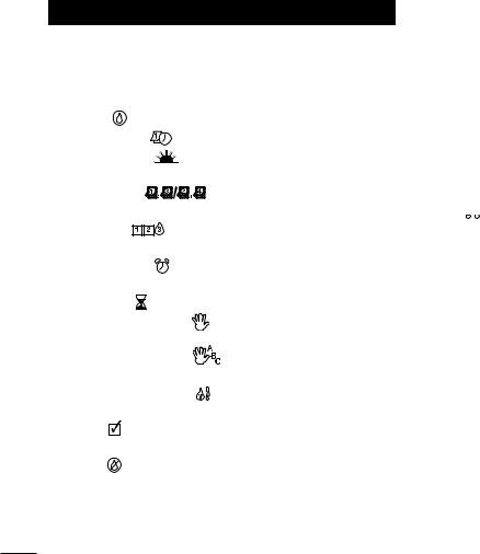
11 -  Symbol - Displayed when setting an automatic watering program start time.
12 -  Symbol - Displayed when watering is on or set. The
 symbol indicates no watering is set.
13 - Station Numbers - Displayed when setting program start time(s) and while a station is running.
14 -  Symbol - Displayed 30 seconds when charging back-up power to retain program memory.
15 - Today/ Symbol - Displayed when setting a Day Interval schedule. The
 symbol is shown when a language other than English is selected.
16 -  Symbol - Displayed when setting the station run time duration.
17 - % Symbol - Displayed when a Watering Budget run time duration adjustment is in use.
18 - Main Display - Shows various time values and controller information.
19 - A B C - Program letter identifiers displayed during programming and operation.
20 - Reset Contacts - Momentarily connect the contacts with a metal conductor such as the tip of a flat screwdriver to reset all programming parameters to the factory default settings.

13 |
|
14 |
|
6 |
|
|
|
15 |
7 |
|
|
|
1 |
|
12 |
|
|
8 |
|
|
|
|
||
|
|
|
16 |
|
|
|
|
|
|
11 |
|
|
2 |
(International Models) |
|
|
|
|
|
|
|
|
3 |
|
19 |
18 |
17 |
4 |
|
|
|
|
|
|
|
|
|
5A |
|
10
|
|
20 |
|
|
9 |
5B |
5C |
|
|
See Troubleshooting. |
|
|
|
Note: Power connection access |
|
cover removed for illustration. |
3 |
|

Controller Installation
|
|
Installing the Cabinet |
|
|
1. For safe, reliable operation, select an installation site |
||
|
|
which can ideally provide the following conditions: |
|
|
|
• For Indoor model controllers – Inside a garage or |
|
|
|
other structure which will provide protection from the |
|
|
|
weather. |
|
|
|
• For outdoor model controllers – Protection from |
|
|
|
irrigation spray, wind and snow. A shaded location is |
|
|
|
recommended. |
|
|
|
• Access to a grounded AC power source (within 4' |
|
|
|
[1.2 m] for indoor models) which is not controlled by |
|
|
|
a light switch or utilized by a high current load |
|
|
|
appliance, such as a refrigerator or air conditioner. |
|
|
|
• Access to the sprinkler control valve wiring and |
|
|
|
optional accessory wiring. |
|
|
2. Drive a wood screw (provided) into the wall at eye |
||
|
|
level (A). Leave the screw extended approximately 1⁄4" |
|
|
|
(6 mm) from the wall. See Figure 1. |
|
|
|
Note: If installing the controller on drywall or |
|
|
|
masonry, install screw anchors. Install the lower |
|
|
|
screw anchor 51⁄4" (133 mm) directly below the top |
|
|
|
screw anchor. |
|
|
3. Remove the lower cabinet access cover by squeezing |
||
|
|
it in on the sides and pulling it directly outward from |
|
|
|
the cabinet. |
|
|
4. Hang the cabinet on the screw using the keyhole slot |
||
|
|
on the back panel (B). Make sure the cabinet slides |
|
4 |
|
down securely on the screw. |
|
5. Install the lower mounting screw and tighten securely. |
|||
Figure 1 |
|
|
B |
A |
|
|
C |
D |
Note: Conduit and adapters are not provided. Install conduit as required by local electrical codes.
6.Remove the power wire access cover. Remove the conduit knockout according to the size of conduit being used. Install 1⁄2" (13 mm) conduit (C) for power/equipment ground wires (outdoor models only) and 3⁄4" (19 mm) or 1" (26 mm) conduit (D) for valve wires (all models).
Connecting the Valves
1.Route the valve wires or wire cable from the valves, into the controller cabinet.
Note: 18 AWG (1.0 mm2) multi-wire sprinkler valve connection cable can be used. This cable is insulated for direct burial and is color-coded to simplify installation. It can be routed directly into the controller through the access hole provided for valve wire conduit (if conduit is not used).
2.Attach the white color-coded wire from the cable to one wire from each valve solenoid. (Either solenoid

 Figure 2


MV |
Valve 1 |
Valve 2 |
Valve 3 |
Valve Common Wire
wire can be used for this connection.) This is called the “Valve Common” wire. SeeFigure 2.
3.Attach a separate cable wire to the remaining wire from each valve solenoid. Note the wire color code used for each valve and the watering station it controls. You will need to have this information when connecting the valve wires to the controller.
4.Secure all wire splices using wire nut connectors. To prevent corrosion and possible short circuits, always use an insulated wire nut, grease cap or similar waterproofing method.
5.At the controller end of the valve connection cable, strip back 1⁄4" (6 mm) of insulation from all cable wires
6.Secure the Valve Common wire to the terminal labeled COM / VC. Connect the individual valve wires to the appropriate station terminals. Connect the master valve wire (if applicable) to the terminal labeled MV.
Note: Connecting a master valve or pump start relay is optional and may not be required for your sprinkler system.
Connecting a Pump Start Relay
 CAUTION: To prevent controller damage, ensure the pump start relay current draw does not exceed 0.4 amps. Do not connect the pump motor starter directly to the controller.
1.Connect a wire pair to the 24 V a.c. pump start relay. Route the wires into the controller housing with the valve wires.
2.Connect one wire to the terminal labeled COM / VC. Connect the remaining wire to the terminal labeled MV. See Figure 3.
Figure 3
|
|
Jumper Wire |
|
Pump Start |
Valve 1 |
Valve 2 |
Valve 3 |
|
|
|
|
Relay |
|
|
|
Valve Common Wire |
|
||
 CAUTION: To prevent pump damage due to
“Dead-heading,” connect a jumper wire from any |
|
|
unused station terminal to a station terminal with a |
5 |
|
valve connected. See Figure 3. |
||
|

Rain Sensor Installation (optional)
A rain sensor can be connected directly to the KwikDial to automatically interrupt watering when it begins to rain. When the rain sensor absorbs rain water, it automatically signals the KwikDial to suspend all watering operations. The display will alternately show “SEN” (sensor) and the time of day until the rain sensor drys out and resets the controller for automatic operation.
1.Route the wire cable from the rain switch sensor into the controller along with the valve wires.
2.Remove the jumper wire from the sensor terminals.
3.Referring to the instructions provided with the rain sensor, connect two wires from the rain sensor designated for “Normally Closed” applications to the sensor terminals. See Figure 4.
4.Place the sensor switch to the ACTIVE position. To turn off the sensor circuit, place the switch in the
BYPASS position. See Figure 4.
Figure 4 |
Sensor |
|
|
|
Switch |
Rain Sensor |
Jumper |
|
Wire |
6 |
|
Connecting the Power Source
Indoor Models
1.Route 6" (15 cm) of the transformer wire cable into the controller through the small opening provided in the base of the cabinet.
2.Tie a knot in the cable just inside the cabinet to prevent the cable wires from pulling out. See Figure 5.
3.Connect the transformer cable red and black wires to the terminals labeled “24 VAC”. Connect the green or green/yellow wire to the ground terminal  .
.
See Figure 5.
4.Plug the transformer into the wall plug socket.
The  symbol will be displayed for 30 seconds while the program memory back-up power is being charged. During this time, the controller can not be operated.
This will only occur when the controller is initially powered up or after a power interruption.
When the controller is ready to operate, the  symbol will disappear and 4:00 PM will be displayed. See “Setting the Date/Time” on page 8 to set the current time and date. To quickly check the sprinkler system operation, refer to the “Test Mode” procedure provided on page 15.

Connecting the Power Source (continued)
Outdoor Models
 WARNING
AC power wiring must be installed and connected by qualified personnel only. All electrical components and installation procedures must comply with all applicable local and national electrical codes. Some codes may require a means of disconnection from the AC power source installed in the fixed wiring and having a contact separation of at least 0.120" (3mm) in the line and neutral poles.
Make sure the power source is OFF prior to connecting the controller.
1.Verify that the power is turned off at the source.
2.Remove the power connection access cover.
3.Route the power and equipment ground wires from the power source through conduit into the controller power connection compartment.
Note: The international model terminal block accepts wire size up to 4 mm2.
4.For domestic and Australian models, refer to Figure 6. Using the wire nuts provided, secure Line to the Black wire, Neutral to the White wire and Equipment Ground to the Green wire.
For international models, refer to Figure 7. Remove 3⁄8" (10 mm) insulation from the wire ends. Using a small flat blade screwdriver, secure Line or Line 1 to L, Neutral or Line 2 to N and Equipment Ground to the ground terminal .
.
Figure 6 |
Figure 7 |
5. Install and secure the power wire access cover.
6. Apply power to the controller. The  symbol will be displayed for 30 seconds while the program memory back-up power is being charged. During this time, the controller can not be operated. This will only occur when the controller is initially powered up or after a power interruption.
When the controller is ready to operate, the  symbol will disappear and 4:00 PM will be displayed. See “Setting the Date/Time” on page 8 to set the current time and date. To quickly check sprinkler system operation, refer to the “Test Mode” procedure
provided on page 15.
7

Programming
Note: To select an optional display language or clock format, refer to “Display Language Option” on page 16.
Setting the Date/Time
1.Turn the control dial to the Date / Time  position.
2.Adjust the clock to the current hour by pressing the  or
or  buttons.
Note: The display will change rapidly if either button is pressed for more than three consecutive seconds.
3.Press the  button to advance to the next field.
4.Adjust the display by pressing the  or
or  buttons.
5.Repeat steps 3–4 to adjust the remaining fields of the Date/Time display.
6.Return the control dial to the Auto position when finished.
Planning Your Watering Schedule
It is often helpful to plan your watering schedule on paper before beginning the programming steps. The information can then be transferred to the Quick Reference Card as a handy reference.
|
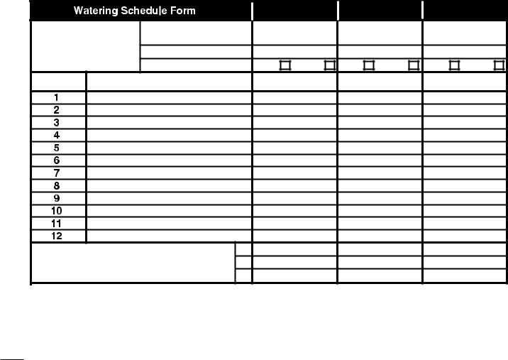
Filling out the Watering Schedule Form |
|
When filling out the form provided on page 10, use a |
|
pencil so changes can be easily made. |
|
Refer to the example shown on the opposite page and fill |
|
out your form in a similar manner. Include the following |
|
information: |
8 |
• Location - Identify the location of each watering |
station area and the type of plant being watered. |
Note: Enter the following information for each program. If the program is not needed, leave its information column blank.
•Watering Day Schedule - For a Calendar schedule, indicate which day(s) of the week watering is desired. For a Day Interval schedule indicate the desired Interval number (1–31). For Odd or Even day watering schedule, simply mark the appropriate box.
•Station Run Time Duration - Indicate the amount of run time (1 minute to 4 hours) for each station. Write “Off” for any station which you do not want to run in the program.
•Program Start Times - Indicate the time(s) of day to start the program. Each program can have up to three start times per watering day.
 Important: The KwikDial can run only one program watering cycle at a time. Therefore, when setting more than one start time for a program or when setting up more than one program, make sure that each program watering cycle will be able to run completely before the next start time occurs. This can be easily determined by totaling up the run time duration of all stations that will operate during the program, then selecting the next start time that can accommodate the completion of the initial watering program. If Water Budget is used to increase run time duration, this must also be considered in the total run time.
It is important to remember that a program start time which occurs while a watering cycle is in progress will be delayed (stacked) until the current watering cycle is finished. If this happens, it may appear that the sprinklers are not shutting off or that they are running at an unexpected time of day. Refer back to this information when setting program start times as described on page 12 and Water Budget on page16.
(Example) |
|
|
|
|
|
|
|
|
|
|
|
Program A |
Program B |
Program C |
|||
|
Calendar Days |
|
|
|
Tue & Fri |
|
|
|
Watering Day Schedule |
|
|
2-day |
|
|
|
3-day |
|
|
Day Interval |
|
|
|
|
|
||
|
Odd/Even |
|
Odd |
Even |
Odd |
Even |
Odd |
Even |
Station |
Location |
|
Run Time |
Run Time |
Run Time |
|||
|
Parkway Lawn |
|
10 min |
|
Off |
|
Off |
|
|
Front Lawn |
|
10 min |
|
Off |
|
Off |
|
|
Front Shrubs |
|
|
Off |
|
5 min |
|
Off |
|
Back Lawn |
|
25 min |
|
Off |
|
Off |
|
|
Garden |
|
|
Off |
|
Off |
|
1 hour |
|
|
1 |
5:00 AM |
4:00 AM |
6:00 AM |
|||
|
Program Start Times |
2 |
|
Off |
|
Off |
|
Off |
|
|
3 |
|
Off |
|
Off |
|
Off |
9
|
|
Program A |
Program B |
Program C |
|||
|
Calendar Days |
|
|
|
|
|
|
Watering Day Schedule |
|
|
|
|
|
|
|
|
Day Interval |
|
|
|
|
|
|
|
Odd/Even |
Odd |
Even |
Odd |
Even |
Odd |
Even |
Station |
Location |
Run Time |
Run Time |
Run Time |
|||
|
|
1 |
|
|
|
|
|
|
Program Start Times |
2 |
|
|
|
|
|
|
|
3 |
|
|
|
|
|
10

About the KwikDial Memory
The KwikDial retains a permanent watering schedule which enables the controller to run the sprinkler system automatically when first powered up or if a power outage lasting longer than 24 hours has erased the KwikDial’s programmable memory. This permanent memory feature enables your landscape to continue being watered if a prolonged power outage occurs while you are away. You may use the permanent schedule as is if it suits your landscape watering needs. Just set the current time and date and the KwikDial is ready to control your sprinkler system automatically.
The permanent schedule operates as follows:
The clock time is set to 4:00 PM, current day is Tuesday and the date is January 1, 2002. All stations will operate in sequence on Program A for 10 minutes. Programs B and C are off. Every day is active in the Calendar schedule, and one program start time occurs at 5:00 AM.
Setting A Calendar Day Schedule
The Calendar Day schedule enables you to set each day of the week as an active or inactive watering day. Each day can be active or inactive in each program (A, B and C).
1. Turn the control dial to the desired day position (Sun 1  , Mon
, Mon  2
2  , etc.).
2.Press the  button as needed to select the desired program. Program letter A, B or C will be displayed.
3.Press either the  or
or  button to make the day active (the watering symbol
  is displayed) or inactive
(the no-watering symbol  is displayed) for the selected program.
4.Repeat steps 1 and 3 for each day of the week.
5.Repeat steps 1–4 for each program as needed.
6.Turn the control dial to the Auto position when finished.
Setting An Odd Or Even Day Schedule
Using an Odd or Even Day watering schedule enables either odd numbered days (1st, 3rd, etc.) or even numbered days (2nd, 4th, etc.) to be selected to water.
1.Turn control dial to the Odd/Even

 position.
2.Press the  button as needed to select the desired program. Program letter A, B or C. will be displayed.
Note: If Int is displayed, a Day Interval watering schedule is already selected for the program and must first be made inactive before an Odd or Even day schedule can be selected. Refer to “Setting A Day Interval Schedule” on page 12 for this procedure.
3.Press the  or
or  button to display Odd or Even.
•To remove an Odd or Even Day schedule from the program, press the  or
or  button to display
-- -- -- (dashes).
4.Repeat steps 2 and 3 for each program as needed.
5.Turn control dial to the Auto position when finished.
Note: Since the first day of every month is an odd number, the last day of every month which is an odd number will not be active. This feature prevents two consecutive watering days from occurring.
Note: To prevent watering on specific days of the week, regardless of schedule type; i.e., never water on Saturday,
turn the control dial to that day and press the  or
or  11 button to display the no-watering symbol
 .
.

Setting A Day Interval Schedule
A Day Interval schedule enables watering days to be set without regard to the actual days of the week. For example, a 1-day interval will water every day, a 2-day interval will water every other day and so on up to a 31-day interval, which will water only once a month.
The active watering day is the last day of the Interval.
In order to establish a reference point for the beginning of the Day Interval, the current day within the interval is also entered. For example, if a 3-day interval is selected and “Today” is entered as day 2 of the interval, then watering will occur tomorrow (the last day of the interval).
1.Turn the control dial to the Interval 


 position.
2.Press the  button as needed to select the desired program. Program letter A, B or C will be displayed.
Note: If Odd or Even is displayed, an Odd/Even watering day schedule is already selected for the program and must first be made inactive before a Day Interval schedule can be used. Refer to “Setting An Odd/Even Day Schedule” on page 11 for this procedure.
3.Press the  or
or  button to select the desired interval number (01–31). The letters DY (day) are displayed to the right of the Day Interval number.
•To remove an Interval schedule from the program, press the  or
or  button to display -- -- -- (dashes).
4.Press the  button. TODAY or
 will be displayed.
5.Use the  or
or  button to select the Today number designation. DY (day) is displayed to the left of the Today number.
6.Repeat steps 2–5 for each program as needed.
12 |
7. Turn the control dial to Auto |
position when finished. |
|
Note: To prevent watering on specific days of the week, regardless of schedule type; i.e., never water on Saturday, turn the control dial to that day and press the  or
or  button to display the no-watering symbol
 .
.
Setting Program Start Time
The program start time is the time of day you select to begin an automatic watering program cycle. When a program starts, each station with a designated run time duration in the program will operate in numerical order, one station at a time. Sometimes it is necessary to run a watering program more than once per day. For example, when watering a new lawn. The KwikDial provides three independent start times per day for each program. Refer to page 8 for additional program start time information
1.Turn the control dial to Start Times 
 1, 2 or 3 position. All station numbers with a designated run
time in the selected program will be indicated at the top of the display. The start time symbol  will be displayed in the lower left corner.
2.Press the  button as needed to select the desired program. Program letter A, B or C will be displayed.
3.Set the start time by pressing the  or
or  button.
Note: The display will change rapidly if either button is pressed for more than three consecutive seconds.
•To remove a start time, press the  or
or  button to display -- -- -- (dashes). The dashes are shown as the clock display passes from 5:59 AM, 11:59 AM, 5:59 PM and 11:59 PM (05:59, 11:59, 17:59 and 23:59).
4.Repeat steps 1 and 3 for each additional start time.
5.Repeat steps 1–4 for each program as needed.
6.Turn the control dial to Auto position when finished.

Setting Station Run Time Duration
The station run time duration is the amount of time a station will operate once it has been started. A station is assigned to a program when it is given a designated run time duration ranging from 1 minute to 4 hours. Each station can have a different run time duration in each program.
Note: You have the option to view station run time duration in minutes only or in hours and minutes. By default, the run time will be displayed in the minutes format; i.e., 1 hour and 30 minutes is displayed as 90M (minutes). To select the alternate format, refer to “Station Run Time Duration Format Option” on page 16.
1.Turn the control dial to the desired Station  number position. The selected station number and the station run time duration symbol
  will be displayed.
Note: For KwikDial controllers with more than six stations, use the  button to switch from the inner labeled stations (1–6) to the outer labeled stations (7–9 or 7–12).
2.Press the  button as needed to select the desired program. Program letter A, B or C will be displayed.
3.Adjust the station run time duration by pressing the
 or
or  buttons.
•To remove the station from the program, decrease the run time duration to less than 1 minute to display -- -- -- (dashes).
4.Repeat steps 1 and 3 to set the run time duration for each station as needed for the selected program.
5.Repeat steps 1–4 for each program as needed.
6.Turn the control dial to Auto  position when finished.
Controller Operation
The KwikDial controller has five modes of operation: Automatic, Manual Station(s), Manual Programs, Test and Off. In the Automatic mode, the controller tracks the time and day and operates the automatic watering schedules as programmed. The Manual Station(s) mode enables an individual station or group of stations to be started and controlled manually. Manual Programs mode enables watering programs to be started manually. Test mode enables a quick, temporary program to be run to test the operation of each station control valve. The Off mode prevents all station operation.
Automatic Operation
Automatic operation will occur whenever the programmed start time and watering day matches the KwikDial’s internal clock and calendar.
The Auto  control dial position is the normal position for the dial when automatic operation is desired. However, the controller will operate automatically when the control dial is in any position other than Off
 . While an automatic watering program is running and the control dial is in the Auto
  position, pressing the
  button will manually advance from the activate station to the next displayed station number in sequence
Manual Operations
Manual controller operations will override all currently active automatic operation and sensor input. Any automatic program start time that occurs during a manual operation will be delayed until the manual
operation is terminated or concluded. Any automatic 13 program delayed past midnight will be postponed.

True Manual Operation
True manual operation allows a single station to be selected and run without regard to run time duration. Once started, the station will run until it is turned off or the controller clock time passes midnight.
1.Turn the control dial to Manual Station(s) position.
2.Press the  button until the desired station number is flashing and the display shows -- -- -- (dashes).
3.Press the  button once to activate the station. The station number and ON will be displayed along with the flashing watering symbol
  . Leave the dial in the Manual Station(s) position. The station will remain on until operation is terminated or until midnight.
•To terminate operation prior to midnight, turn the control dial to any other position.
4.Turn the control dial to Auto position when finished.
Timed Manual Operation
Timed manual operation enables any stations to be given a temporary station run time duration and operated in sequence.
1.Turn the control dial to Manual Station(s) position.
2.Press the  button until the desired station number is flashing and the display shows -- -- -- (dashes).
3.Press the  or
or  button to select a temporary station run time duration from 1 to 240 minutes.
Note: The temporary station run time will not affect the station’s run time within any automatic program.
4.Press the  button to select the station.
5.Repeat steps 2–4 to select additional stations.
14(These stations will not start immediately, but will operate in sequence.)
6.After all desired stations for timed manual operation
have been selected, turn control dial to the Auto  position.
• To manually advance through the station sequence,
press the  button (the control dial must be in the Auto
  position to use this feature).
•To terminate the timed manual operation, either skip
through the remaining station sequence with the  button, or turn control dial to the Off
  position
for at least three seconds.
Manual Program Operation
Manual program operation enables automatic watering programs to be manually started and operated in sequence.
1.Turn the control dial to the Manual Programs  position. The display will show MAN, the currently selected program letter and stations assigned to the program.
2.Press the  button as needed to display a program you wish to run. All stations which currently have a station run time duration assigned to the selected program will be shown at the top of the display.
3.Press the  button to start the program (or select an additional program). The program letter and the watering symbol
  will begin flashing.
4.Repeat steps 2 and 3 to select additional programs to operate in sequence.
5.Turn the control dial to the Auto position. The remaining run time duration for the currently operating station will be displayed. Station numbers and programs waiting to run will also be shown.

•To manually advance through the station sequence, for the program, press the  button. If more than one program was selected, continue pressing the
  button to advance to the next program in sequence.
•To terminate the manual program operation, either skip through the remaining stations and programs in
sequence with the  button, or turn the control dial to the Off
  position for at least three seconds.
Test Mode
Selecting this function enables you to run a quick, temporary watering program to test the operation of each watering station.
Note: To terminate the test mode at any time, turn the control dial to the Off  position for three seconds.
1.Turn the control dial to the Test 
 position. The display will show 2M for a 2-minute run time for each station.
2.Press the  or
or  button to change the run time from 1 to 9 minutes if desired.
Note: The run time used in the test program is temporary and will not alter the station run time set for automatic program operation.
3.Press the  button to start the test.
4.Turn the control dial to Auto position. The watering symbol
  and the operating station number will be flashing. The remaining station numbers to be tested will be displayed. As the test time is completed for each station, the station number disappears and the next station in sequence starts.
•By leaving the dial in the Auto position, the controller completes the test of each station then returns to the Automatic mode.
•To manually advance to the next station in
sequence, press the  button. Advancing past the last station will end the test program.
Rain Delay Mode
This feature enables all automatic watering operations to be delayed from 1 to 7 days. When the number of delay days elapses, the controller returns to automatic operation.
1.Turn the control dial to the Off  position.
2.Press the  or
or  button to select the desired number of rain delay days (1–7). The number will be displayed with OFF; i.e. OFF 2 for a 2-day delay.
3.Turn the control dial to the Auto position. The number of rain delay days remaining will be displayed alternately with the current time of day.
•To terminate the rain delay operation at any time, repeat steps 1–3 to display OFF.
Turning Off the KwikDial
When the control dial is turned to the Off  position, OFF will be displayed and will flash for three seconds. The three-second delay allows the control dial to be turned past the Off
  position momentarily without initiating the Off command. When OFF stops flashing, any watering operation currently in progress will be turned off and programmed automatic operation will be prevented.
For extended shutdown of the sprinkler system, leave the control dial in the Off  position. OFF will be displayed 15 until the control dial is turned to another position.

Special Functions
The Special Functions  dial position provides access to various control features and optional display formats. The special functions are: Water Budget, Station Run Time Duration Format Option, Display Language Option, Clock Time Format Option, Program Erase and Enable/Disable Expansion Port.
Water Budget
Water Budget enables you to conveniently decrease or increase the run time duration currently set for each station assigned to a selected program. The adjustment can be made in 10% increments from 0% (program Off) to 200% of the normal (100%) run time.
Note: Water Budget is applied to programs A, B and C independently. For example, applying Water Budget to program A will not alter the run time duration of any stations assigned to Program B or C.
1.Turn control dial to the Special Functions  position.
2.Press the  button as needed to select the desired program. The currently set percentage for the program will be displayed.
3.Press the  or
or  button to select the desired adjustment percentage; i.e., 90% equals a 10% reduction of station run time and 200% doubles the station run time.
4.To apply Water Budget to another program, repeat steps 2 and 3.
5.Turn control dial to the Auto  position when finished.
16Note: During operation, the display will show the adjusted run time for each station as it starts running.
As a reminder of Water Budget setting (other than 100%), the % symbol will be displayed with the current time.
See “Important” on page 8 for additional information.
Station Run Time Duration Format Option
The station run time duration can be displayed in either minutes or hours and minutes format. To change the current run time format, use the following procedure:
1.Turn the control dial to the Special Functions position.
2.Press the  button as needed to display MMM or
HH:MM.
3.Press the  or
or  button to select the desired format:
MMM = minutes; i.e., 1 hour and 30 minutes is displayed as 90M.
HH:MM = hours and minutes; i.e., 1 hour and 30 minutes is displayed as 1:30.
4. Turn control dial to the Auto position when finished.
Display Language Option
Various display information can be viewed in any of five languages: English, Spanish, French, German or Italian. To change the display language, use the following procedure:
1.Turn control dial to the Special Functions  position.
2.Press the  button as needed to display ENG.
3.Press the  or
or  button to select the desired language: ESP (Spanish), FRA (French), ITA (Italian) or DEU (German).
4.Turn the control dial to the Auto  position when finished.
 Loading...