


Wireless RainSensorTM
Models RS1000 and RFS1000 (+Freeze)
User’s Guide
Contents |
Page |
|
|
|
Component Overview . . . . . . . |
. . . |
. .2 |
|
|
Quick Start Installation Instructions . |
.3 |
|
|
|
Detailed Installation Instructions |
. . . .4 |
|
|
|
• Connecting the Receiver |
|
|
|
|
Control Wires . . . . . . . . . . . |
. . .4–5 |
|
|
|
• Connecting the Receiver |
|
|
|
|
Power Wires . . . . . . . . . . . . |
. . . . |
.6 |
|
|
• Initial Receiver Testing . . . . |
. . . . |
.6 |
|
|
• Rainfall Adjustment . . . . . . . . |
. . . |
.7 |
|
|
• Vent Ring Adjustment . . . . . . |
. . . |
.7 |
|
|
• Mounting the Sensor Transmitter |
.7 |
|
|
|
• Freeze Sensor Installation . . |
. . . |
.8 |
|
|
Wireless RainSensor Operation |
. . . .9 |
|
|
|
• Normal Operation . . . . . . . . . |
. . . |
.9 |
|
|
• Smart Bypass . . . . . . . . . . . . |
. . . |
.9 |
|
|
• Power Down . . . . . . . . . . . . . |
. . . |
.9 |
|
|
• Receiver Learn Mode . . . . . . |
. . . |
.9 |
|
|
• Attention Required . . . . . . . . . |
. . . |
.9 |
|
|
Battery Replacement . . . . . . . . . |
. . . |
10 |
|
|
Changing Sensor/Transmitter Code .10 |
|
|
||
Troubleshooting . . . . . . . . . . . . . |
. . . |
11 |
|
|
Specifications . . . . . . . . . . . . . . |
. . . |
12 |
Sensor/Transmitter |
Receiver |
Electromagnetic Compatibility |
|
12 |
||
. . . |
|
|
||
Technical Assistance Numbers |
. . . .12 |
|
|
|
Introduction
Congratulations on your purchase of the Irritrol Wireless RainSensor. The Wireless RainSensor components are designed for easy installation, so your sensor-controlled irrigation system will be up and running in minutes.
Before attempting the installation, please read through these instructions in their entirety, and refer to the installation instructions for your irrigation system controller/timer in regards to connecting a rain sensor or rain switch. The Wireless RainSensor is designed to work with either Normally Open or Normally Closed sensor circuits.
 Important: Please note the following information regarding installation and use of the Wireless RainSensor components:
•The RainSensor Receiver Module is designed to operate with 24 VAC power only. Connecting the receiver wiring to 120/240 VAC power will result in equipment damage and may void warranty.
•Installation methods must comply with all applicable national and local building codes. If you are unsure about proper wiring practices, have a qualified contractor perform the installation for you.
•The Receiver cover should always be used when the Receiver is installed outdoors.
•The Sensor/Transmitter should never be submerged in water or installed inside a rain gutter.

Component Overview |
Figure 1 |
2 |
Receiver (Figure 1) |
1 |
|
|
3 |
|
1 - Weather-resistant Cover: |
|
|
|
|
|
Slides upward to remove. Protects |
|
|
the receiver module when located |
|
4 |
outdoors. Keep the cover installed |
|
|
at all times other than when |
|
5 |
manually operating the receiver. |
|
|
2 - Antenna wire: |
|
6 |
Straighten vertically for the best |
|
|
|
|
|
reception. |
|
|
3 - Sensor Status Indicator: |
|
|
Steady light - Sensor is active |
|
|
(either rain or freeze). |
|
|
Blinking light - Indicates receiver |
|
7 |
has been bypassed for one rain |
|
|
cycle. Smart BypassTM button |
|
|
pressed once. Press again to exit |
|
|
bypass mode. |
|
|
4 - Signal Indicator: Indicates quality of last received signal. Steady light - good signal.
Blinking light - fair signal.
No light - poor signal (relocate Sensor Transmitter).
5 - Smart BypassTM Button:
Press to temporarily override the sensor when active. Press and hold for 5–7 seconds to turn off the receiver.
6 - Power Indicator:
Steady light - 24 VAC power is connected.
Blinking light - Sensor/Transmitter battery power low, or other communication problem.
No light - Unit is off or is disconnected from 24 VAC.
7 - Multi-wire Cable: 20" (50cm) color-coded wires provided for controller connections.
Sensor/Transmitter (Figure 2) |
Figure 2 |
1 |
||
1 |
- Spindle: Press down and hold to |
|
||
|
|
|||
|
manually test transmitter operation. |
|
2 |
|
2 |
- Rainfall Adjustment Cap: Adjusts the |
4 |
||
|
||||
|
Sensor/Transmitter to signal the |
|
3 |
|
|
receiver when the accumulated rainfall |
|
||
|
|
|
||
|
reaches 1/8" (3mm), 1/4" (6mm), 1/2" |
5 |
|
|
|
(12mm) or 3/4" (19mm). |
|
||
|
|
|
||
3 |
- Vent Ring: Adjust “dry-out” rate. |
|
|
|
4 |
- Universal Mounting Bracket with |
|
|
|
|
Quick-ClipTM: Simplifies installation on |
|
|
|
|
rain gutter, or roof eaves, fences, etc. |
|
|
|
|
Sensor/Transmitter adjusts easily to |
|
|
|
|
the vertical position. |
|
|
|
5 |
- Conduit Adapter: Alternative |
|
|
|
|
mounting option for conduit mount. |
|
|
|
6 |
- Antenna Wire: Straighten downward |
|
6 |
|
|
for maximum range. |
|
|
|
2
Quick Start Installation Instructions
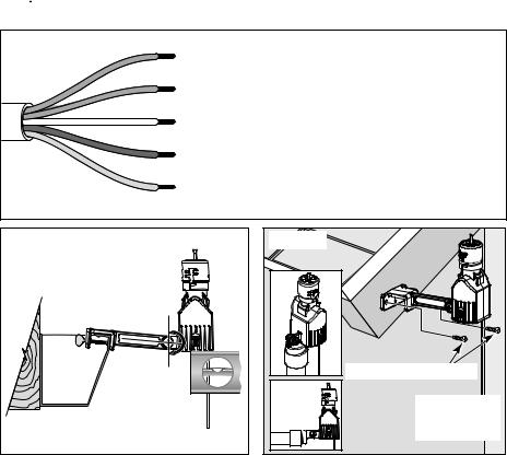
The following instructions are provided for the experienced installer. Refer to Figures 3–5 below.
Note: When installing Sensor/Transmitter model RFS1000 for freeze detection, refer to additional freeze sensor installation information on page 8.
1.Disconnect power to the irrigation system controller.
2.Always mount the Receiver FIRST, adjacent to the controller with either the provided stainless steel screws or double-sided foam tape.
3.Attach Receiver control wires to the sensor inputs OR to break the valve common:
a.Disconnect common valve wire and common pump/master valve wire (if present).
b.Attach White wire to common wire(s) with a wire connector.
c.Attach Brown wire (only) to common terminal on controller.
4.Connect the Red wires to the controller’s 24 VAC power source terminals.
5.Straighten the Receiver antenna wire upward and the Sensor/Transmitter antenna wire downward.
6.While holding the Sensor/Transmitter at close range to the Receiver, press and hold the spindle to test the wiring. The Power, Signal and Sensor Status indicators should be ON.
7.Adjust the Rainfall Adjustment Cap to the desired rainfall activation amount.
8.Adjust the Vent Ring to the desired dry-out rate.
9.Mount the Sensor/Transmitter in an unobstructed location away from sprinklers.
 Important: Reconfirm proper operation of the Sensor/Transmitter at the final mounting location.
Figure 3 |
Red |
|
|
|
Red |
|
White |
|
Brown |
|
Yellow |
To 24 VAC
To 24 VAC
To Sensor Terminal or to Break Valve Common
To Sensor Terminal (Normally Closed) or to Break Valve Common
To Sensor Terminal (Normally Open)
(For Normally Open sensor, see Detailed Instructions)
Figure 4 |
Press and hold |
Figure 5 |
|
|
down to test |
|
|
Do not over-tighten |
|
|
|
thumbscrew |
|
|
|
|
Antenna wire |
|
Stainless Steel |
|
Conduit |
|
|
|
extended |
|
|
|
Mount |
Antenna wire |
|
|
straight down |
||
|
|
extended |
|
|
|
|
|
Rain gutter (cross section view) |
|
straight down |
|
|
|
||
3
Detailed Installation Instructions
There are two main components of the Wireless RainSensor: the Receiver and the Sensor/Transmitter. The Receiver is installed adjacent to or within the cabinet of the irrigation system controller. The Sensor/Transmitter is installed outdoors where it is exposed to unobstructed rainfall.
Mounting the Receiver
1.Always mount the Receiver FIRST, adjacent to the controller with either the provided stainless steel screws or double-sided foam tape. The connection wire cable is 20" (50cm) long, so before attaching the Receiver, make sure the wires will easily reach the controller’s connection terminals.
Wiring the Receiver
There are two parts involved in wiring the Receiver:
Part 1: Attach the Receiver control wires (similar to hard-wired sensors). Part 2: Attach the low-voltage power wires to supply 24 VAC to the Receiver.
Part 1 - Control Wire Connection
The Receiver control wires are used to interrupt the common wire of the valves or they can be connected directly to the sensor input terminals of the controller (if provided).
1.Disconnect power to the controller.
2.Follow applicable wiring procedure A or B or C.
Note: The following diagrams are representations only and do not depict actual controller layouts. Refer to the installation instructions provided with your controller for specific wire connection information.
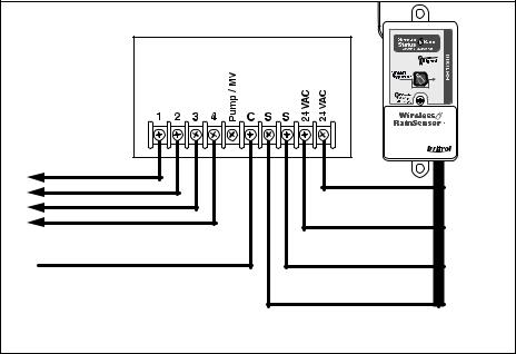
A. Controllers with sensor inputs (with or without pump/master valve):
Refer to Figure 6. Find the controller sensor terminals (generally marked “Sensor”, “SEN” or “S”) and directly connect the White and Brown* wires to these terminals in any order. There may be a jumper wire or tab connecting the terminals that must be removed and/or a sensor bypass/control switch that must be activated.
Figure 6
|
Irrigation System Controller |
|
||
To Valves |
White |
Brown |
Red |
Red |
|
|
|
|
|
|
|
* |
|
|
Common From Valves
*Note: Use Yellow wire in place of Brown if a Normally Open sensor is required.
4
 Loading...