

Page 1
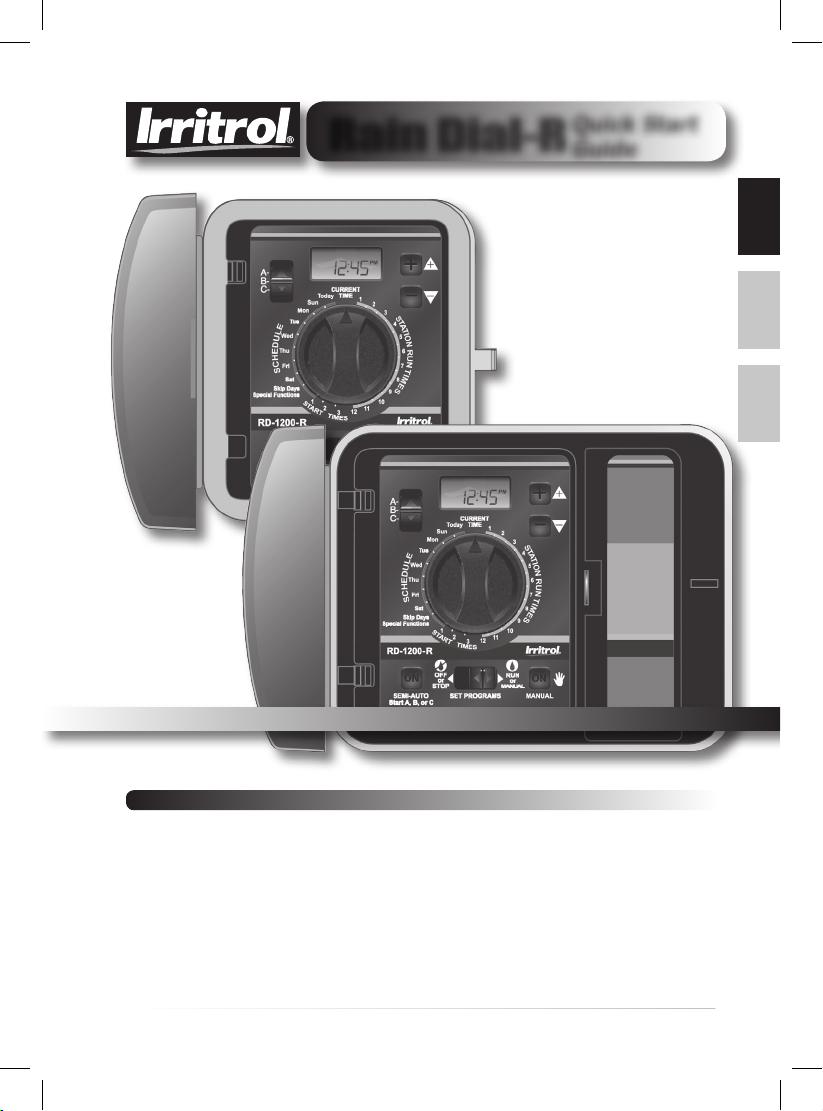
Rain Dial-R
Indoor and Outdoor 6, 9, and 12-station Models
Quick Start
Guide
EnglishEspañol
Français
Introduction
Thank you for purchasing the Rain Dial-R controller from Irritrol. The Rain Dial-R
controller has many easy-to-use and powerful features to help keep your landscaping
healthy and beautiful. And with a compatible rain or soil sensor, it is possible to save
money too.
This Quick Start guide presents basic information to get you started irrigating quickly.
For the complete user guide with advanced functionality and explanation, go to:
www.irritrol.com/controllers/controllers_raindial.html
.
1
Page 2

Table of Contents
Features 2
Control Module Interface 2
Battery Installation 3
Internal Controller Components 4
Controller Installation 5
Installing the Controller Cabinet 5
Connecting the
Valve Control Wiring 5
Connecting an
Earth Ground Device 6
Connecting the Power Source 6
Controller Station Test 8
Setting Up an Irrigation Schedule 8
Manual Operation 10
Contact Information 12
Specifications 12
Features
• Modular design. Permits easy access to connection terminals and battery. “Snap-out”
design allows the controller to be programmed from any location.
• Remote control ready
• Three independent watering programs
• Three start times per program
• Scheduling flexibility
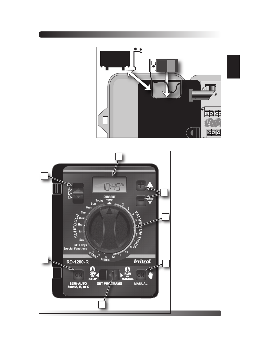
Control Module Interface (see opposite graphic)
1 - Program Switch
Three-position slide switch used to select Program A, B or C for setup, program review
and manual operation.
2 - LCD Display
High-contrast LCD panel displays all controller programming and operating information.
3 - Plus and Minus Buttons
Push buttons used to increase and decrease display values during controller setup,
programming and manual operations. Adjusts values incrementally (press and release) or
by rapid scrolling (press and hold).
4 - Dial
A 25-position rotary switch used to select stations, start times, watering days and special
functions for setup, programming and manual operations.
5 - Manual Button
Push button used to start and control manual operations by station. Also serves as
a “Next” button to step forward through various setup, programming and manual
operations.
6 - Function Switch
A three-position slide switch used to select one of three controller
function modes:
Off or Stop - Stops all current watering operations, and prevents all automatic
Set Programs - Enables automatic watering program setup values to be selected
Run or Manual - Normal switch position for all automatic and manual watering
7 - Semi-Auto Start Button
Push button used to manually start an automatic watering Program. Also used to initiate
the Station Test Run operation.
and manual operations.
and changed.
operations.
2
Page 3
Battery Installation
MV/
9 10 11 12
1 2 3 4 5 6
24 VAC
VC
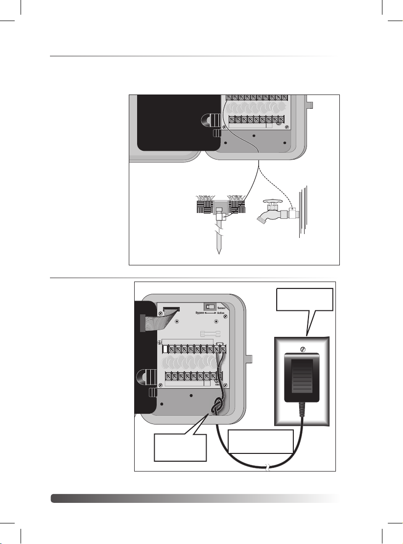
Install a 9V battery for two reasons:
1. Program the controller
from any location.
2. Maintain controller time
and date during power
outages.
Steps:
1. Open controller door.
2. Slide battery
compartment cover off.
3. Attach the battery clip
to a 9V battery.
4. Install battery into
compartment and
replace cover.
5. The display will begin
flashing 12:00 AM.
1
English
EARTH
GROUND
7 8
2
3
4
7
6
5
3
Page 4
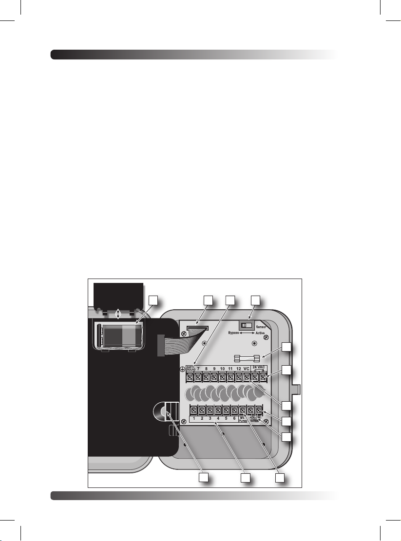
Internal Controller Components
1 - Battery Compartment
Snap-in cover provides easy access to 9V
alkaline battery.
2 - Control Module Ribbon Cable
Quick disconnect cable control module from
cabinet for Armchair Programming or service.
3 - Earth Ground Terminal
Wire connection terminal for earth ground
conductor.
4 - Sensor Bypass Switch
Switch controls (optional) rain/freeze sensor
input.
5 - Safety Fuse
2A Slow-blow fuse protects against shortcircuit overload on the 24 VAC input power.
6 - Power Transformer Connection
Terminals (24 VAC)
Wire connection terminals for 24 VAC
plug-in transformer and power connection
point for (optional) wireless rain or rain/
freeze sensors.
7 - Valve Common Terminal (VC)
Wire connection terminal for the valve (field)
common wire.
8 - Rain Sensor Terminals (Sensor)
Wire connection terminals for (optional)
Irritrol RainSensorTM model RS500, RS1000,
or RFS1000.
9 - Sensor Terminal Jumper
Sensor terminal jumper wire (removed
only when a rain or rain/freeze sensor is
connected).
10 - Master Valve/Pump Terminal (MV/Pump)
Wire connection terminal for (optional)
master valve or pump start relay.
11 - Valve Station Terminals
Valve connection terminals – one terminal for
each valve. (Terminal layout varies by model.
12-station model shown.)
12 - Handheld Remote Control Plug-in Port
Modular connector port required for the
Irritrol handheld remote control system
model R-100-KIT or CLIMATE LOGI weather
sensing system.
1 2
12
4
3
5
6
7
8
9
11
10
4
Page 5
Controller Installation
Installing the Controller Cabinet
Select a sheltered location for the indoor model Rain Dial-R such as a garage or service room,
preferably within 5’ (1.5m) of a grounded electrical outlet. For outdoor controllers, choose a location
that protects against direct exposure to sun and contact with irrigation spray, and is at least 5’ (1.5m)
away from any motorized equipment.
1. Drive the provided stainless steel screw into a wall stud at a eye-level, leaving 1/4” (6.4mm) of
the screw shaft exposed.
Note: Use screw anchors when installing on drywall or masonry.
2. Hang the controller on the screw using the keyhole-shaped slot.
3. To secure the controller, drive one or two screws through the lower mounting holes.
Note: The lower mounting holes in the Outdoor cabinet have a thin veneer that is easily pierced
when installing the mounting screw during installation.
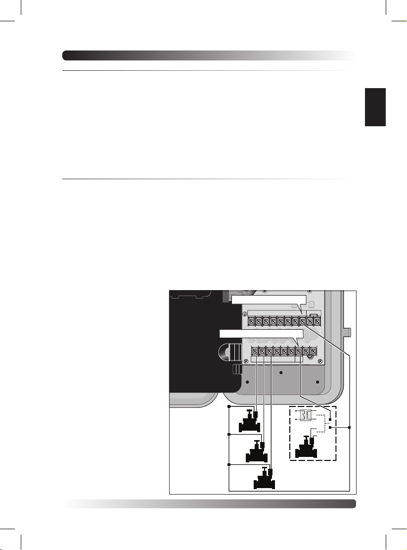
Connecting the Valve Control Wiring
For best results, use connection wire cable specifically designed for direct burial for automatic irrigation
systems. Use 18-AWG wire for connections up to 800’ from the controller, or heavier 14-AWG (2.0mm2 )
wire for connections up to 2000’. A separate wire for each valve (and relay) connection and at least one
common (return) wire is required.
Note: If control wire conduit is required, install it at this time. For conduit installation, use the 3/4”
(19mm) access hole in the indoor cabinet, or the threaded 1.25” NPT opening in the outdoor cabinet.
1. Route the control wire from the controller location to the valve(s).
2. Attach a separate control wire to either lead of each valve solenoid.
3. To provide a common (return) wire, attach the remaining lead of each valve solenoid to a single wire.
Note: To prevent corrosion and a possible short circuit, use waterproof wire connectors on all
external wire splices.
For reference at the controller, note the wire color used for each valve connection and its
corresponding watering zone.
4. Route the cable through the
largest opening in the base of
the controller cabinet or through
conduit if installed. Remove the
cable jacket to expose about 8”
of wires. Carefully remove 3/8” of
insulation from the end of each
wire to be connected.
5. Secure each valve wire to
numbered terminal in the
preferred operating sequence
order.
6. Connect the common wire to the
terminal labeled “VC.”
7. If applicable, connect one leg
of the master valve or pump
start relay control wire to the
terminal labeled “MV/PUMP”, and
the remaining leg to the valve
common wire.
Note: The controller does not
supply power to operate a pump.
The pump start relay must have
a nominal coil voltage of 24 VAC,
rated at 0.375A maximum.
Sprinkler
Control Valves
Valve Common Terminal
EARTH
789101112
GROUND
Master Valve/Pump Terminal
123456
1
2
Pump Start Relay
or Master Valve
3
24 VAC
VC
-
+
MV/
Sensor
Pump
24V Relay
MV
Common Wire
English
5
Page 6
Connecting an Earth Ground Device
EARTH
GROUND
MV/
Pump
Sensor
+
-
789101112
123456
24 VAC
VC
EARTH
GROUND
MV/
Pump
Sensor
+
-
789101112
123456
24 VAC
VC
Note: In order for the electrical surge components built into your Rain Dial-R to function
properly, the controller must be connected to an earth ground device, such as a copper-clad
ground rod or metal water pipe, using solid copper wire. This connection is especially important
when the controller is installed in a lightning-prone area.
1. Connect a 12–16
AWG ( 2mm2–
1.3mm2 ) solidcopper wire to
the ground device
and route into the
controller through
an access opening
in the base of the
cabinet.
2. Secure the ground
wire to the terminal
labeled “Earth
Ground.”
8' (2.4 m) Copper-clad
Ground Rod (in moist soil)
Metal Water Pipe
Connecting the Power Source - Indoor Model
1. Route the plug-in
transformer cable
through the small hole
provided in the bottom
of the cabinet.
2. Tie a knot in the cable
to provide a strain
relief, and connect the
wires to the terminals
labeled “24 VAC” (in
either order).
3. Close the control
module and plug the
transformer into a wall
outlet. The controller is
now ready to program
and operate.
Note: To immediately
test-run the Rain
Dial-R irrigation control
system, refer to the
“Controller Station Test
Feature” on page 8.
Strain-relief Knot
If there are 3 wires,
connect the green wire
to “Earth Ground”.
24 VAC, 30VA
Transformer
6
Page 7
Connecting the Power Source - Outdoor Models
+
MANUAL
Today
Sun
Mon
2
3
4
5
6
7
8
9
10
11
12
3
2
1
PM
S
T
A
R
T
T
I
M
E
S
V
A
L
V
E
R
U
N
T
I
M
E
S
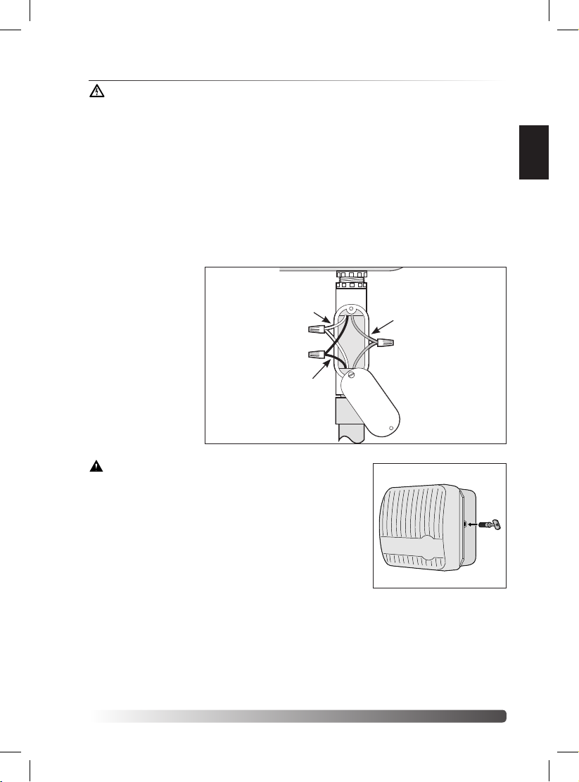
Warning: All electrical components and connection methods must comply with
all applicable national and local electrical codes including installation by qualified
personnel. These codes may require a junction box installed on controller’s 1/2”
(13mm) NPT nipple and a means in the fixed wiring of disconnecting AC power
having a contact separation of at least 0.120” (3mm) in the line and neutral poles.
The connection wire must have insulation rated @ 105° C min.
The controller must be connected to a grounded power source. Do not connect
to one phase of a 3-phase power supply used by a pump or other electrical
equipment.
Prior to connecting controller wiring, verify that power has been turned off at the
source by using an AC volt meter.
1. Install a 1/2” (13mm) NPT conduit body to the transformer threaded fitting. From the
conduit body, install electrical conduit routing to the AC power source (per electrical code).
2. Pull 14 AWG through the conduit into the conduit body.
3. Using twist-on wire
connectors, attach the
mating wires as shown
at right.
4. Close and secure the
conduit body cover.
Neutral or L1 to
White or Blue
Conduit Body
Equipment Ground to
Green or Green/Yellow
5. Apply power to the
controller and check
controller operation.
If the controller is not
operating, disconnect
Hot or L2 to
Black or Brown
the power at the
source and have a
qualified electrician
check for possible
Electrical Conduit
short circuit.
Caution: For maximum protection of the controller
electronic components when installed outdoors,
always keep the cabinet cover closed and locked
whenever possible. Store the cabinet keys in a safe,
convenient location.
Key
English
7
Page 8
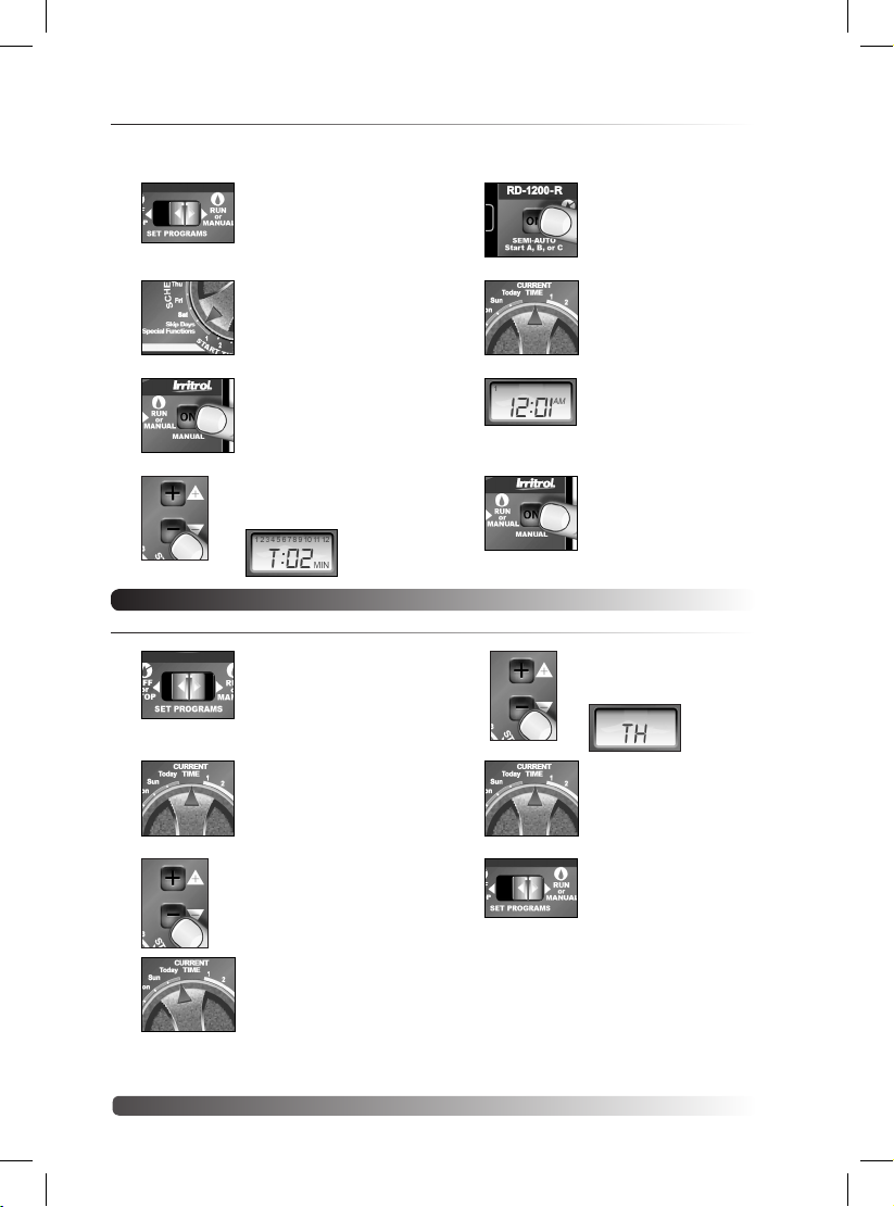
Controller Station Test Feature
Run a Station Test to check proper valve operation. The test cycle enables all valve stations
to operate in sequence, from 1–10 minutes.
1. Set Function switch to
Run.
5. Push Semi-Auto to
start watering cycle
(station 1).
2. Turn Dial to Skip Days. 6.
3. Push MANUAL button
4.
once.
Adjust run time.
A 2-minute test run is
set by default.
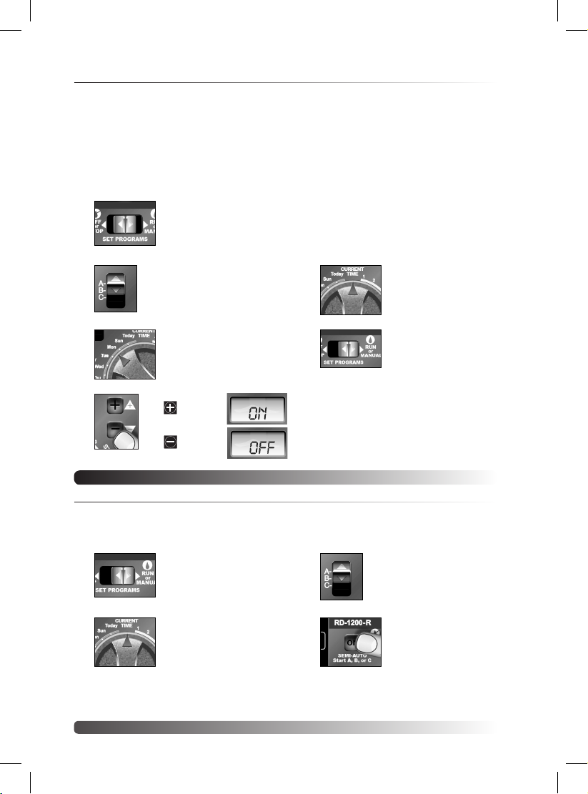
Setting Up an Irrigation Schedule
Setting the Current Time and Day
1. Function switch to Set
2. Turn Dial to Current
3. Set current time.
Programs.
Time.
Pay attention to “AM”
and “PM”.
Turn Dial to
Current Time.
7. Display shows current
8. Manual advances the
5.
6. Return Dial to Current
7. Function switch back
time and what station is
running.
station sequence.
Select the correct day*.
Display shows
day abbreviation.
Time.
to Run.
4. Turn Dial to Today.
*Note: If Odd/Even schedule or Monthly Water Budget is used,
the current day of the week is preset and cannot be changed.
8
Page 9
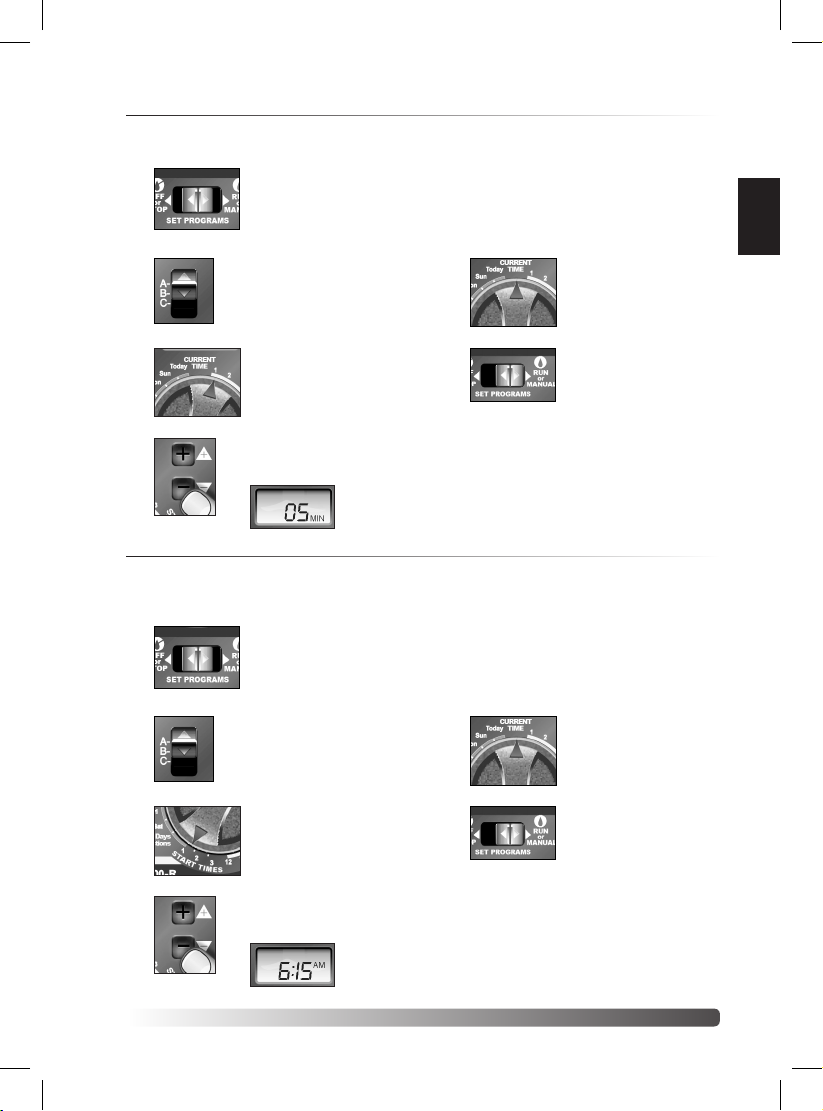
Setting the Valve Run Time Duration
Each valve station can have an individual run time assignment in each Program. Run time can
be set for 1–59 minutes (in 1-minute increments) or 1–5.9 hours (in 1/10-hour increments).
1. Function switch to Set
2. Select Program
Programs.
A, B, or C.
5. Repeat steps 3 and 4 for all valves.
Switch to a different Program. Repeat
steps 3 and 4 as needed.
6. Return Dial to
Current Time.
English
3. Turn Dial to desired
4.
Valve Number.
Set valve run time.
Display shows
valve run time.
7. Function switch back
to Run.
Setting the Program Cycle Start Time(s)
Each Program can have three separate start times. For mature landscapes, one start time per
Program is generally sufficient. For new lawns, two or three start times with short valve run
times can provide the additional irrigation required for grow-in.
1. Function switch to Set
2. Select Program
3. Turn Dial to Start Time
4.
Programs.
A, B, or C.
(Make sure to use
Program A and reset its
default values.)
1 (or 2 or 3).
Set start time.*
Display shows
start time.
5. Repeat steps 3 and 4 to set additional
start times.
Switch to a different Program. Repeat
steps 3 and 4 as needed.
6. Return Dial to
7. Function switch back
Current Time.
to Run.
*Note: To remove a start time, select
Off, displayed between 11:59–12:00 and
5:59–6:00 (AM and PM).
9
Page 10
Setting the Program Watering Day Schedule
Watering days can be scheduled for each Program using one of the following methods:
Weekdays Schedules watering for specific days of the week.
Skip Day Schedules watering days by
Odd/Even Date Schedules watering days based on Odd- or Even- numbered calender days.
To set a Weekdays Schedule:
1. Function switch to Set
other-day (02) etc. Skip Days is addressed in the online User Manual.
Odd/Even Date is addressed in the online User Manual.
Programs.
interval frequency
5. Repeat steps 3 and 4 to turn On and
Off days as needed.
Switch to a different Program. Repeat
steps 3 and 4 as needed.
; e.g., every day (01), every-
2. Select Program
3. Turn Dial to desired
4.
A, B, or C.
Weekday.
turns day
turns day
6. Return Dial to
7. Function switch back
Current Time.
to Run.
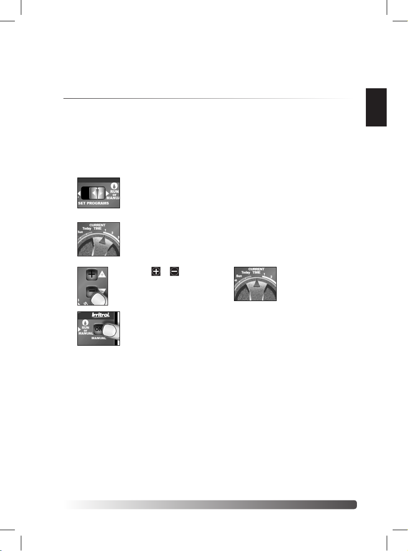
Manual Operations
Semi-Automatic Program Operation
Semi-Automatic Program operation enables an automatic Program watering cycle to be started
manually at any time. Once running, the manual advance feature enables you to step through
the programmed station sequence.
1. Place the Function
switch in the Run
position.
2. Turn the Dial to the
Current Time position.
3. Select Program
4. Press the Semi-Auto
A, B, or C.
button to start the
watering cycle.
Note: Once started, the station sequence can be manually advanced by placing the Dial
to Current Time and pressing the Manual button.
10
Page 11
Note: The Manual Advance feature applies to all Automatic, Semi-automatic and Station
Test watering operations for the selected Program.
Note: To terminate watering operations, place the Function switch momentarily in the
OFF or Stop position.
Manual Station Operation
Manual station operation provides manual control at the individual station level and provides
the following four control options:
• Station(s) can be operated for a one-time run duration without altering the station’s set
run time in an automatic Program.
• Operation can be limited to only one station running manually or set to allow three
stations to run at the same time.
• Works with the Manual Advance feature to move up through the station sequence.
1. Place the Function
switch in the Run
position.
5. If this is the only station to be run
manually, skip step 6 and
continue at step 7 below.
English
2. Turn the Dial to the
3.
4. Press the Manual
Station Number to be
manually operated.
Use the /
buttons to set a manual
operation run time
ranging from
1 minute to 5.9 hours.
button to start the
operation.
6. To add additional stations to the
manual run operation, repeat steps 2
through 4 as needed, then continue
at step 7.
7. Turn the Dial to the
Current Time position.
Note: Depending upon the Stack/Overlap setting, additional
stations selected (beyond the one or three option setting) will register as OFF when
entered with the Manual button. However, they will be placed (stacked) in the manual
sequence to run.
Note: Once started, the station sequence can be manually advanced
by pressing the Manual button.
Note: To terminate manual watering operations, place the Function switch momentarily
in the OFF or Stop position.
11
Page 12

Contact Information
Modelos para interiores y exteriores de 6, 9 y 12 estaciones
If you encounter problems during setup and/or operation of the Rain Dial-R controller, please
contact an authorized Irritrol product expert for assistance via phone or email.
U.S./Canada:
Phone: 1-800-634-8873 (7:30 am–4 pm,
M–F, PT)
E-mail: irrigationsupport@irritrol.com
Europe:
Phone: +39-076540191
E-mail: intlirrigationsupport@irritrol.com
Australia:
Phone: +61 8 8300 3633
E-mail: intlirrigationsupport@irritrol.com
Specications
Input Power
• Outdoor Model: 120 VAC 60 Hz, 30 VA (Domestic)
230/240 VAC, 50 Hz, 30VA
(International)
• Indoor Model: 24 VAC, 60 Hz, 30 VA (Domestic)
(from plug-in transformer) 24 VAC, 50 Hz, 30 VA
(International and Australian)
All Models:
• Station Output: 24 VAC at 0.5A, 1.0A (maximum total)
• Master Valve/Pump Start Relay Output: 24 VAC at 0.375A
• 2.0A Slow-blow Fuse
• Battery Back-up (time, day and date)
• Operating temperature range: 32˚F to 140˚F (0˚C to 60˚C)
Caution: The Rain Dial is designed to operate 24 VAC valve solenoids rated at 0.25A (6
VA). Total current load during operation must not exceed 1.0A. A maximum of two solenoids
per station terminal may be used if the total station load does not exceed 0.5A. No more than
three solenoids (plus MV/Pump circuit) should operate concurrently. In irrigation systems where
multiple controllers are used, each controller must utilize a separate valve common circuit.
FCC Rules
This equipment has been tested and found to comply with the limits for a Class B digital device, pursuant
to Subpart J of Part 15 of the FCC Rules. These limits are designed to provide reasonable protection against
harmful interference in a residential installation. This equipment generates, uses and can radiate radio
frequency energy and, if not installed and used in accordance with the instructions, may cause harmful
interference to radio communications. However, there is no guarantee that interference will not occur in a
particular installation. If this equipment does harmful interference to radio or television reception, which can
be determined by turning the equipment off and on, the user is encouraged to try to correct the interference
by one or more of the following measures:
1. Reorient or relocate the receiving antenna.
2. Increase the separation between the equipment and receiver.
3. Connect the equipment into an outlet on a circuit different from that to which the receiver is connected.
4. Consult the dealer or an experienced radio/TV technician for help.
The user may find the following booklet prepared by the Federal Communications Commission helpful:
“How To Identify and Resolve Radio-TV Interference Problems.” This booklet is available from the U.S.
Government Printing Office, Washington, DC 20402, stock # 004-000-00345-4.
International: This is a CISPR 22 Class B product.
© 2013 Irritrol www.irritrol.com Form Number 373-0799 Rev. A
12
Page 13

Rain Dial-R
Guía
Rápida
EnglishEspañol
Français
Modelos para interiores y exteriores de 6, 9 y 12 estaciones
Introducción
Gracias por comprar el Rain Dial-R controlador de Irritrol. El Rain Dial-R controlador
tiene muchas características fáciles de usar y de gran alcance para ayudar a
mantener su jardín saludable y hermoso. Y con un sensor compatible de lluvia o de
tierra, se puede ahorrar dinero también.
Esta Guía Rápida presenta información básica para empezar a regar rápidamente.
Para obtener la guía del usuario completa con funcionalidad avanzada y la
explicación, vaya a:
www.irritrol.com/controllers/controllers_raindial.html
.
13
Page 14

Tabla de contenidos
Características . . . . . . . . . . . . . . . . . . 14
Interfaz del módulo de control . . . . . . . 14
Instalación de la pila . . . . . . . . . . . . . 15
Componentes internos del controlador 16
Instalación del controlador . . . . . . . . . 17
Instalación del armario del Controlador 17
Conexión del cableado de control de las
válvulas . . . . . . . . . . . . . . . . . . . . . . 17
Conexión a una toma de tierra . . . . . . . 18
Conexión del suministro eléctrico . . . . . 18
Prueba de estaciones . . . . . . . . . . . . . 20
La Creación de un Programa Riego . . . . 20
Operaciones manuales . . . . . . . . . . . . 22
Información de contacto . . . . . . . . . . 24
Especificaciones . . . . . . . . . . . . . . . . 24
Características
• Diseño modular. Permite un fácil acceso a los terminales de conexión y la batería. “Snap-
out” diseño permite que el programador puede programar desde cualquier lugar.
• Preparado para el control remoto
• Tres programas de riego independientes
• Tres horas de arranque por programa
• Programación de flexibilidad
Interfaz del módulo de control (véase al lado gráco)
1 - Interruptor de Programa
Un interruptor deslizante de tres posiciones que se utiliza para seleccionar el programa A,
B o C para su configuración, repaso de programas u operación manual.
2 - Pantalla LCD
El panel LCD de alto contraste muestra toda la información sobre los programas y sobre el
funcionamiento del controlador.
3 - Teclas +/-
Estas teclas se utilizan para aumentar o reducir los valores mostrados en la pantalla durante
la configuración, la programación y las operaciones manuales. Los valores se ajustan de uno
en uno (pulsar y soltar) o en modo de avance rápido (pulsar y mantener pulsado).
4 - Dial
Un interruptor rotativo con 25 posiciones, utilizado para seleccionar estaciones, horas de
arranque, días de riego y funciones especiales durante la configuración, la programación y
las operaciones manuales.
5 - Tecla Manual
Se utiliza para iniciar y controlar la activación manual de las estaciones. También sirve como
tecla de avance durante diversas operaciones de configuración, programación y manuales.
6 - Interruptor de función
Un interruptor deslizante de tres posiciones utilizado para seleccionar entre los tres modos
de funcionamiento del controlador:
Off or Stop - Detiene todas las operaciones de riego actualmente en marcha, e
Set Programs - Permite seleccionar y modificar los valores de configuración de los
Run or Manual - La posición normal del interruptor para todas las operaciones de
7 - Tecla de arranque semiautomático
Se utiliza para arrancar manualmente un programa de riego automático. Se utiliza
también para iniciar la Prueba de funcionamiento de estaciones.
impide toda operación automática o manual.
programas de riego.
riego automáticas y manuales.
14
Page 15

Instalación de la pila
MV/
9 10 11 12
4 5 6
24 VAC
VC
La instalación de la pila de 9V (a
suministrar por el usuario) tiene
dos funciones importantes: primero,
permite completar la programación
de Rain Dial-R antes de su
instalación, y segundo, mantiene el
módulo de control sincronizado con
la fecha y hora actuales durante
posibles cortes de energía eléctrica
de más de 24 horas de duración.
1. Abra la puerta del controlador.
2. Abra el módulo de control
EARTH
GROUND
7 8
sujetándolo por el borde derecho
(en el modelo para exteriores,
presione la pestaña de liberación
del módulo).
1 2 3
3. Retire la tapa del compartimiento
de la pila presionando hacia abajo y hacia fuera en el borde superior de la misma.
4. Enchufe el conector en una pila alcalina de 9 V.
5. Coloque la pila en el compartimiento y vuelva a colocar la tapa.
6. La pantalla empezará a parpadear con el mensaje 12:00 AM (pulse cualquier tecla para
detenerla).
2
1
3
Español
4
7
5
6
15
Page 16

Componentes internos del controlador
1. Compartimiento de la pila
La tapa a presión ofrece un acceso fácil a
la pila alcalina de 9V.
2. Cable plano del módulo de control
Permite desconectar rápidamente el
módulo de control del armario para
facilitar la programación “desde casa” o el
mantenimiento.
3. Terminal de puesta a tierra
Terminal para la conexión de un cable de tierra.
4. Interruptor de anulación del sensor
Interruptor que controla la entrada del
sensor (opcional) de lluvia/heladas.
5. Fusible de seguridad
Un fusible de fundido lento de 2A que
protege el controlador contra sobrecargas
por cortocircuito en el suministro eléctrico
de 24 VCA.
6. Terminales de conexión del
transformador de corriente (24 VCA)
Terminales de conexión para los cables
del transformador de 24 VCA y punto de
conexión para la alimentación del control
remoto opcional CMR-KIT.
7. Terminal común de las válvulas (VC)
Terminal para la conexión del cable común
(campo) de las válvulas.
8. Terminales del sensor de lluvia (Sensor)
Terminales para la conexión de los cables del
RainSensorTM modelos RS500, RS1000, o
RFS1000 de Irritrol (opcionales).
9. Puente de los terminales del sensor
Puente de los terminales del sensor (Se retira
únicamente para conectar un sensor de lluvia
o de lluvia/heladas.)
10. Terminal de válvula maestra/bomba
(MV/PUMP)
Terminal para la conexión de los cables de la
Válvula maestra o Relé de arranque de bomba
(opcional). (El puente de los terminales del
sensor se retira únicamente para efectuar la
conexión del RainSensor.)
11. Terminales de válvulas
Terminales para la conexión de las válvulas –
Un terminal para cada válvula. (La disposición
de los terminales varía según el modelo – El
modelo ilustrado es el de 12 estaciones.)
12. Conector para el control remoto de mano
Control de conexión modular para el sistema
de control remoto de mano modelos CMR-KIT
o KSR-KIT-K de Irritrol.
16
1 2
12
4
3
5
6
7
8
9
11
10
Page 17

Instalación del controlador
Instalación del armario del Controlador
Seleccione un lugar protegido para la instalación del modelo para interiores del Rain Dial-R, como por
ejemplo un garaje o cuarto de máquinas, preferentemente a menos de 5’ (1,5 m) de una toma de
corriente eléctrica con toma de tierra. Para modelos de exteriores, seleccione un lugar que los proteja
contra la exposición directa a la luz solar y el contacto con el agua de riego pulverizada, que esté a
una distancia mínima de 5’ (1,5 m) de cualquier equipo con motor.
1. Atornille el tornillo de acero inoxidable suministrado en un montante de pared a una altura
cómoda, dejando expuesto aproximadamente 1/4” (6,4 mm) del tornillo.
Nota: Utilice anclajes de tornillo para la instalación sobre paredes de cartón-yeso o de obra.
2. Cuelgue el programador en el tornillo usando la ranura en forma de bocallave.
3. Sujete el programador con uno o dos tornillos colocados en los taladros de montaje inferiores.
Nota: Los taladros de montaje inferiores del armario para exteriores están obturados por una
lámina fina de plástico que se penetra fácilmente al instalar el tornillo de montaje.
Conexión del cableado de control de las válvulas
Para obtener los mejores resultados, utilice cable de conexión diseñado específicamente para sistemas
de riego automático. Utilice cable de 18 AWG para distancias de hasta 800’ del controlador, o cable más
grueso de 14 AWG (2,0 mm2) para distancias de hasta 2000’. Se requiere un cable individual para cada
válvula (y relé) y al menos un cable común (retorno).
Nota: Si es necesario instalar conductos para el cableado, instálelos ahora. Para la instalación de
conductos, utilice el taladro de acceso de 3/4” (19 mm) del armario para interiores, o el orificio roscado
de 1,25 “NPT del armario para exteriores.
1. Tienda el cable de control desde el controlador hasta las válvulas.
2. Conecte un cable de control individual a cualquiera de los cables del solenoide de cada válvula.
3. Conecte el otro cable del solenoide de cada válvula a un cable individual para formar un cable
común (de retorno).
Nota: Para evitar la corrosión y posibles cortocircuitos, utilice conectores de cable impermeables en
todos los empalmes exteriores.
Anote el color del hilo utilizado para cada válvula así como su zona de riego correspondiente para su
referencia al hacer las conexiones en el controlador.
4. Pase el cable al interior del programador a través de la abertura mayor de la base del armario del
controlador o a través del
conducto, si se instaló. Retire
la cubierta del cable para dejar
expuesto aproximadamente 8” de
los hilos. Retire cuidadosamente
3/8” de aislamiento del extremo de
cada hilo que se va a conectar.
5. Conecte el cable de cada válvula
al terminal numerado en el orden
secuencial preferido para su
operación.
6. Conecte el cable común al
terminal marcado “VC”.
7. En su caso, conecte un hilo del
cable de control de la válvula
maestra o del relé de arranque
de bomba al terminal marcado
“MV/PUMP”, y el otro hilo al cable
común de las válvulas.
Nota: El controlador no
suministra la potencia necesaria
para activar una bomba. El relé
de arranque de la bomba debe
tener una tensión de bobina
nominal de 24 VCA, con una
potencia máxima de 0,375 A.
The pump start relay must have
a nominal coil voltage of 24 VAC,
rated at 0.375A maximum.
Válvulas de control
de los aspersores
Terminal común de las válvulas
EARTH
789101112
GROUND
Terminal de válvula maestra/bomba
123456
1
2
Relé de arranque de
bomba o válvula maestra
3
Hilo común
24 VAC
VC
+
MV/
Sensor
Pump
Relé 24 V
MV
-
17
Español
Page 18

Conexión a una toma de tierra
EARTH
GROUND
MV/
Pump
Sensor
+
-
789101112
123456
24 VAC
VC
EARTH
GROUND
MV/
Pump
Sensor
+
-
789101112
123456
24 VAC
VC
Nota: Para que los componentes de protección contra sobrecargas de su Rain Dial-R funcionen
correctamente, el controlador debe conectarse a un dispositivo de tierra, como por ejemplo
una pica de tierra revestida de cobre o una tubería de agua metálica, usando cable de cobre
macizo. Esta conexión es especialmente importante cuando se instala el controlador en una
zona propensa a rayos.
1. Conecte un cable
de cobre macizo
de 12–16 AWG (2
mm2– 1,3 mm2)
al dispositivo de
tierra y llévelo
al controlador
a través de la
abertura de la base
del armario.
2. Conecte el cable
de tierra al
terminal marcado
“Earth Ground”.
Pica de tierra de 2,4 m
revestida de cobre
(en suelo húmedo)
Tubería de agua
metálica
Conexión del suministro eléctrico - Modelos interiores
1. Introduzca el cable
del transformador
externo a través del
taladro pequeño
provisto en la parte
inferior del armario.
2. Haga un nudo en el
cable para protegerlo
contra tirones, y
conecte los cables
a los terminales
marcados “24 VCA”
(en cualquier orden).
3. Cierre el módulo de
control y enchufe el
transformador en una
toma de corriente.
El controlador está
preparado para su
programacíón y uso.
Nudo de
seguridad
Transformador de
24 VCA, 30VA
18
Page 19

Nota: Para hacer una prueba inmediata del sistema de control de riego Rain Dial-R,
+
MANUAL
Today
Sun
Mon
2
3
4
5
6
7
8
9
10
11
12
3
2
1
PM
S
T
A
R
T
T
I
M
E
S
V
A
L
V
E
R
U
N
T
I
M
E
S
consulte “Prueba de funcionamiento de estaciones” en la página 20.
Modelos para exteriores
Advertencia: Todos los componentes eléctricos y métodos de conexión deben
cumplir la normativa nacional y local aplicable sobre instalaciones eléctricas,
incluyendo la instalación por personal cualificado. Estas normas pueden exigir
la instalación de una caja de empalmes en el conector NPT de 1/2” (13 mm) del
controlador y algún medio de desconectar el suministro eléctrico CA en el cableado
fijo, con una separación entre contactos de al menos 0,120” (3 mm) en los polos de
fase y neutro. El cable de conexión debe contar con aislamiento resistente a 105 °C
como mínimo.
El controlador debe conectarse a una toma de corriente con tierra. No lo conecte a una
fase de un suministro eléctrico trifásico usado por una bomba u otro equipo eléctrico.
Antes de conectar los cables del controlador, compruebe que la electricidad ha sido
desconectada en la toma de corriente, usando un voltímetro de corriente alterna.
1. Conecte un registro de conducto de 1/2” (13 mm) NPT al conector roscado del
transformador.
Desde el registro de
conducto, instale el
conducto eléctrico
hasta la toma de
corriente eléctrica
CA (de acuerdo
con la normativa
sobre instalaciones
eléctricas).
2. Pase cable de 14
AWG a través del
conducto hasta el
registro.
3. Usando conectores
de cable, conecte
los cables según
se muestra en la
Figura 9.
4. Cierre y afiance el registro del conducto.
5. Encienda el suministro eléctrico del controlador y compruebe el funcionamiento del
controlador. Si el controlador no funciona, desconecte el suministro eléctrico en su
origen y haga que un instalador eléctrico cualificado compruebe si hay algún posible
cortocircuito.
Cuidado: Para asegurar la máxima protección de los componentes electrónicos
del controlador cuando está instalado en el exterior, mantenga siempre cerrada
la cubierta del armario, con llave siempre que sea posible. Guarde las llaves del
Neutro o L1 a
Blanco o Azul
Fase o L2 a
Negro o Marrón
Conducto eléctrico
Registro de conducto
Tierra a Verde o
Verde/Amarillo
armario en un lugar seguro y de fácil acceso.
Español
19
Page 20

Prueba de estaciones
Ejecutar una prueba de estaciónes para comprobar el funcionamiento de la válvula. El ciclo de
prueba permite que todas las estaciones de válvulas para operar en secuencia, de 1-10 minutos.
1. Ponga el interruptor de
función a Run.
5. Empuje Semi-Auto
para iniciar el ciclo de
riego (estación 1).
2. Gire el dial a Skip
3. Oprime el botón
4.
Days.
MANUAL una vez.
Ajuste el tiempo de
ejecución.
Test de 2 minutos está
configurado de fabrica.
6.
7. La pantalla muestra
8. Botón Manual avanza
Gire el Dial a la
posición Current Time.
la hora actual y qué
estación está en
funcionamiento.
la secuencia de
estaciones.
La Creación de un Programa Riego
Ajuste de la fecha y la hora actuales
1. Ponga el interruptor
2. Gire el Dial a la
3. Ajustar la hora actual. 7. Gire el Dial a la
de función a Set
Programs.
posición Current Time
5. Oprime el botón
6.
MANUAL una vez.
Seleccione el día
correcto*.
Pantalla muestra
abreviatura de los días.
posición Current Time.
4. Gire el Dial a hoy
(Today).
8. Ponga el interruptor de
función a Run.
*Nota: Si se utiliza un calendario de días Pares/Impares o Ajuste porcentual mensual, el día
actual de la semana está preestablecido y no puede modificarse.
20
Page 21

Ajuste del tiempo de riego de las válvulas
Cada estación puede tener asignado un tiempo de riego individual en cada programa. El
tiempo de riego puede ajustarse de 1 – 59 minutos (en incrementos de 1 minuto), o de 1 –
5,9 horas (en incrementos de 1/10 de hora).
1. Ponga el interruptor
2. Seleccione Programa
de función a Set
Programs.
A, B, o C.
5. Repita los pasos 3 y 4 para todas las
válvulas.
Cambie a un programa diferente.
Repita los pasos 3 y 4, según sea
necesario.
6. Gire el Dial a la
posición Current Time.
3. Gire el dial a la válvula
4.
número deseado.
Establecer el tiempo de ejecución
de la válvula.
La pantalla muestra el tiempo de
funcionamiento de la válvula.
7. Ponga el interruptor de
función a Run.
Ajuste de las horas de arranque de los programas
Cada programa puede tener tres horas de arranque independientes. Para paisajes maduros,
una sola hora de arranque por programa suele ser suficiente. Si el césped es nuevo, el uso
de dos o tres horas de arranque con tiempos de riego cortos puede proporcionar el riego
adicional necesario para el arraigamiento.
1. Ponga el interruptor
2. Seleccione Programa
3. Gire el Dial a Start
4.
de función a Set
Programs.
A, B, o C.
Time 1 (hora de inicio
1) o 2 o 3.
Establecer la hora de inicio.*
La pantalla muestra la hora
de inicio.
5. Repita los pasos 3 y 4 para establecer
tiempos de arranque adicionales.
Cambie a un programa diferente.
Repita los pasos 3 y 4, según sea
necesario.
6. Gire el Dial a la
7. Ponga el interruptor de
posición Current Time.
función a Run.
*Nota: Para eliminar un tiempo de inicio,
seleccione Off (apagado), aparece entre
11.59–12.00 y 5.59 –6.00 (AM y PM).
Español
21
Page 22

Ajuste del calendario de días de riego
Pueden programarse días de riego para cada Programa, usando uno de los métodos siguientes:
Días de la semana Programa el riego en días específicos de la semana.
Saltar días Programa los días de riego por intervalos, por ejemplo cada día (01), días
Día Par/Impar Programa los días de riego en los días Pares o Impares. Consulte el Manual
Para establecer un calendario por Días de la semana:
1. Ponga el interruptor
2. Seleccione Programa
alternos (02), etc. Consulte el Manual del usuario en línea.
del usuario en línea.
de función a Set
Programs.
A, B, o C.
5. Repita los pasos 3 y 4 para activar On
y Off días según sea necesario.
Cambiar a un programa diferente.
Repita los pasos 3 y 4, según sea
necesario.
6. Cuando haya terminado,
gire el Dial a la
posición Current Time.
3. Gire el dial a día de la
4.
semana deseado.
enciende el día
enciende el día
7. Ponga el interruptor de
función a Run.
Operaciones manuales
Operación semiautomática de programas
La operación Semiautomática permite arrancar manualmente un ciclo de riego automático en
cualquier momento. Una vez en marcha, la función manual le permite avanzar paso a paso
por la secuencia de estaciones programadas.
1. Ponga el interruptor de
2. Gire el Dial a la
Nota: Una vez iniciada la secuencia, puede avanzar manualmente por las estaciones
poniendo el Dial en Current Time y pulsando la tecla Manual.
Nota: La función Avance Manual es aplicable a todas las operaciones de riego Automático,
Semiautomático y de Prueba de estaciones para el Programa seleccionado.
función a Run.
posición Current Time.
22
3. Seleccione Programa
4. Oprime el botón Semi-
A, B, o C.
Auto para iniciar el
ciclo de riego.
Page 23

Nota: Para terminar las operaciones de riego, ponga el interruptor de Función
momentáneamente en la posición OFF or Stop.
Operación manual de estaciones
La activación manual de las estaciones proporciona un control manual a nivel de estaciones
individuales, con las cuatro opciones de control siguientes:
• Es posible poner en marcha una o más estaciones sin modificar el tiempo de riego
establecido para dicha estación en un programa automático.
• Es posible limitar la operación a una sola estación bajo control manual, o a tres
estaciones al mismo tiempo.
• Se utiliza la función de Avance Manual para recorrer la secuencia de estaciones.
1. Ponga el interruptor de
función a Run.
5. Si esta es la única estación para ser
ejecutado manualmente, omita el paso
6 y continúe en el paso 7.
Español
2. Gire el selector hacia
la Estación Número de
accionar manualmente.
3. Utilice los botones
/ para fijar un
tiempo de ejecución de
la operación manual
desde 1 minuto hasta
5,9 horas.
4. Oprime el botón
Manual para iniciar la
operación.
6. Para agregar estaciones adicionales
para la operación de riego manual,
repita los pasos del 2 al 4 según sea
necesario, continúe con el paso 7.
7. Gire el Dial a la
posición Current Time.
Nota: Dependiendo del ajuste de Apilamiento/Solapamiento, las estaciones adicionales
seleccionadas (más allá de la selección de una o tres estaciones) se verán como
Desactivadas (OFF) al introducirse con la tecla Manual. No obstante, serán insertadas
(apiladas) en la secuencia de operación manual.
Nota: Una vez iniciada la secuencia, puede avanzar manualmente por las estaciones
pulsando la tecla Manual.
Nota: Para terminar las operaciones de riego manuales, ponga el interruptor de Función
momentáneamente en la posición OFF or Stop.
23
Page 24

Información de contacto
Modèles intérieurs et extérieurs - 6, 9, et 12 stations
Las soluciones ofrecidas pueden ayudarle a resolver algunos de los problemas que pueden
surgir durante la configuración y/o el uso del controlador Rain Dial-R.
Si el problema no aparece en la lista o si no se resuelve con las soluciones indicadas, solicite la
ayuda de un experto en productos Irritrol por teléfono o correo electrónico.
EE.UU./Canadá:
Teléfono: 1-800-634-8873
(7:30 am–4 pm, L–V, PT)
E-mail: irrigationsupport@irritrol.com
Europa:
Teléfono: +39-076540191
E-mail: intlirrigationsupport@irritrol.com
Australia:
Teléfono: +61 8 8300 3633
E-mail: intlirrigationsupport@irritrol.com
Especicaciones
Modelos para exteriores:
Entrada: 120 VCA 60 Hz, 30 VA (EE.UU.),
230/240 VCA, 50 Hz, 30VA (Internacional)
Modelos para interiores:
Consumo (transformador externo): 24 VCA, 60 Hz, 30 VA (EE.UU.),
24 VCA, 50 Hz, 30 VA (Internacional y Australia)
Todos los modelos:
• Salida a estaciones: 24 VCA a 0,5A, 1,0A (total máximo)
• Salida a válvula maestra/relé de arranque de bomba: 24 Vca, a 0,375A
• Fusible de 2,0A de fundido lento
• Pila de respaldo (hora, día y fecha)
• Intervalo de temperaturas de operación: 32°F a 140°F (0°C a 60°C)
Cuidado: El controlador Rain Dial está diseñado para accionar solenoides de válvula de
24 VCA de 0,25 A (6 VA). La carga de corriente total durante el uso no debe superar 1,0A.
Puede utilizarse un máximo de dos solenoides por terminal de estación, siempre que la carga
total por estación no supere 0,5 A. No deben estar activados más de tres solenoides (más el
circuito MV/Bomba) de forma simultánea. En sistemas de riego en los que se utilizan múltiples
controladores, cada controlador debe usar un circuito de válvula común independiente.
Normas FCC (EE.UU.)
Este equipo ha sido probado y se ha verificado que cumple los límites de un dispositivo digital de la Clase B,
conforme con la Parte 15 Apartado J de la normativa FCC. Estos límites están diseñados para proporcionar una
protección razonable contra interferencias dañinas en una instalación residencial. Este equipo genera, utiliza y
puede radiar energía de radiofrecuencia, y si no es instalado y utilizado con arreglo a las instrucciones, puede
causar interferencias dañinas para las radiocomunicaciones. Sin embargo, no podemos garantizar que no se
van a producir interferencias en una instalación determinada. Si este equipo produce interferencias dañinas
para la recepción de radio o televisión, lo cual puede determinarse apagando y encendiendo el equipo, se
recomienda al usuario que intente corregir la interferencia usando una o más de las siguientes medidas:
1. Reorientar o reubicar la antena receptora.
2. Aumentar la separación entre el equipo y el receptor.
3. Conectar el equipo a un circuito eléctrico diferente al del receptor.
4. Consultar al concesionario o a un técnico experto en radio/televisión.
El usuario puede encontrar útil el siguiente folleto preparado por la Federal Communications Commission:
“How To Identify and Resolve Radio-TV Interference Problems.” Este folleto puede obtenerse en la U.S.
Government Printing Office, Washington, DC 20402, EE.UU, pieza nº 004-000-00345-4.
Internacional: Éste es un producto CISPR 22 Clase B.
© 2013 Irritrol www.irritrol.com Form Number 373-0799 Rev. A
24
Page 25

Rain Dial-R
Modèles intérieurs et extérieurs - 6, 9, et 12 stations
Démarrage
Rapide Guide
EnglishEspañol
Français
Introduction
Merci d’avoir acheté le contrôleur Rain Dial-R de Irritrol. Le contrôleur Rain Dial-R
dispose de nombreuses fonctionnalités faciles à utiliser et puissant pour aider à
garder votre aménagement paysager sain et beau. Et avec la pluie ou le sol capteur
compatible, il est possible d’économiser de l’argent aussi.
Ce guide de démarrage rapide présente des informations de base pour vous
aider à démarrer irriguer rapidement. Pour le mode d’emploi complet avec des
fonctionnalités avancées et d’explication, aller à:
www.irritrol.com/controllers/controllers_raindial.html
.
25
Page 26

Table des matières
Caractéristiques 26
Éléments du programmateur 26
L’installation de la pile 27
Composants internes 28
Installation du programmateur 29
Installation du boîtier 29
Connexion du câblage 29
Un dispositif de mise à la terre 30
L’alimentation électrique 30 et 31
Fonction d’essai de voies 32
Procédures de programmation 32
Opérations manuelles 34
Information de Contact 36
Fiche technique 36
Caractéristiques
• Conception modulaire – Permet un accès facile aux bornes de câblage des vannes et au
logement de la pile. La conception détachable du module de commande permet de le
retirer facilement pour la programmation à distance.
• Adapté à la commande à distance
• Trois programmes d’arrosage indépendants
• Trois heures de démarrage par programme
• Échelonnement/chevauchement de programmes
Éléments du Programmateur (voir graphique opposé)
1 - Interrupteur de programme
Interrupteur à glissière à 3 positions servant à sélectionner le programme A, B ou C pour
la configuration, la révision et le fonctionnement manuel.
2 - Écran à cristaux liquides
L’écran à cristaux liquides à contraste élevé affiche toutes les informations de
programmation et de fonctionnement du programmateur.
3 - Touches “+” et “–”
Elles servent à augmenter ou diminuer les valeurs affichées pendant la configuration du
programmateur, la programmation et les opérations manuelles. Elles modifient les valeurs
progressivement (pressions brèves) ou rapidement (pression prolongée).
4 - Cadran
Cadran rotatif à 25 positions servant à sélectionner les voies, les heures de démarrage,
les jours d’arrosage et les fonctions spéciales pour la configuration, la programmation et
les opérations manuelles.
5 - Touche “Manual”
Touche servant à démarrer et commander les opérations manuelles par voie. Sert aussi
de touche “Suivant” pour avancer dans les diverses configurations, programmations et
opérations manuelles.
6 - Interrupteur de fonction
Interrupteur à glissière à trois positions servant à sélectionner l’un des trois modes de
fonctionnement du programmateur :
Off or Stop - Cette position interrompt toutes les opérations d’arrosage en cours
Set Programs - Cette position permet de sélectionner et de modifier les paramètres
Run or Manual - Position normale de l’interrupteur pour toutes les opérations
7 - Touche Semi-Auto Start
Touche utilisée pour démarrer manuellement un programme d’arrosage automatique.
Également utilisée pour lancer l’essai de voies.
26
et empêche toutes les opérations automatiques et manuelles.
des programmes d’arrosage automatiques.
d’arrosage automatiques et manuelles.
Page 27

L’installation de la pile
MV/
9 10 11 12
1 2 3 4 5 6
24 VAC
VC
Installez une pile 9V pour deux raisons :
1. Programmer le
programmateur de
n’import quel endroit.
2. Maintenir heure et date
du programmateur
pendant les coupures
électriques.
Étapes:
1. Ouvrez la porte du
programmateur.
2. Faites glisser
compartiment couvercle
des piles.
3. Fixez la pince de pile à
une pile alcaline de 9 V.
4. Placez la pile dans son
compartiment et remettez le couvercle en place.
5. 12:00 AM commencera à clignoter à l’écran.
1
EARTH
GROUND
7 8
Français
2
3
4
7
6
5
27
Page 28

Composants internes du programmateur
1 - Compartiment de la pile
Le couvercle à enclenchement permet l’accès
facile à la pile alcaline de 9 V.
2 - Câble plat du module de commande
Câble à débranchement rapide pour enlever
le module de commande du boîtier afin de
faciliter la programmation à distance ou les
entretiens.
3 - Borne de terre
Borne de connexion du fil de de terre.
4 - Interrupteur de dérivation de
pluviomètre
Commande l’entrée de capteur pluie/gel
(option).
5 - Fusible de sécurité
Le fusible à action retardée de 2 A protège
l’alimentation 24 V CA contre les surcharges
dues aux courts-circuits.
6 - Bornes de connexion du
transformateur (24 V CA)
Bornes de connexion pour transformateur
enfichable 24 V CA et point de connexion
d’alimentation pour système de commande à
distance CMR-KIT (option).
7 - Borne commune des vannes (VC)
Borne de connexion du fil commun des
vannes.
8 - Bornes de pluviomètre (Sensor)
Bornes de connexion pour Irritrol
RainSensorTM, modèle RS500, RS1000 ou
RFS1000 (option).
9 - Fil volant de capteur
Fil volant de borne de capteur (uniquement
enlevé quand un capteur de pluie ou pluie/
gel est connecté.).
10 -
Borne de vanne maîtresse/pompe
(MV/Pump)
Borne de connexion pour relais de vanne
maîtresse ou démarrage de pompe (option)
(Fil volant de borne de capteur uniquement
débranché pour connecter le RainSensor.).
11 - Bornes de connexion de vannes
Bornes de connexion de vannes – une borne
par vanne. (La disposition des bornes varie
d’un modèle à l’autre – modèle à 12 voies
montré.)
12 -
Port de connexion de
télécommande portable
Port de connexion modulaire requis pour le
système de télécommande portable Irritrol,
R-100-KIT ou CLIMATE LOGIC, le système de
capteur climatique sans fil.
28
1 2
12
4
3
5
6
7
8
9
11
10
Page 29

Installation du programmateur
Installation du boîtier du programmateur
Choisissez un emplacement abrité pour le modèle Rain Dial-R intérieur, comme un garage ou un local
technique, de préférence à 1,5 m (5’) ou moins d’une prise reliée à la terre. Pour les programmateurs
extérieurs, choisissez un emplacement à l’abri des rayons du soleil et de tout jet d’arrosage, et à 1,5
m (5’) au moins de tout équipement motorisé.
1. Vissez la vis en acier inoxydable fournie dans un montant de cloison, à une hauteur convenable,
en la laissant dépasser d’environ 6,4 mm (1/4”).
Remarque : Utilisez des chevilles si vous installez le programmateur sur une cloison sèche ou
en maçonnerie.
2. Accrochez le programmateur à la vis en utilisant la fente en forme de serrure.
3. Insérez une ou deux vis dans les trous de montage inférieurs pour fixer le programmateur.
Remarque : Les trous de montage inférieurs du boîtier extérieur sont recouverts d’une fine
couche facile à percer avec les vis de montage pendant l’installation.
Connexion du câblage de commande des vannes
Pour des résultats optimaux,
utilisez un câble de branchement
spécialement conçu pour les
systèmes d’arrosage automatiques.
Utilisez un câble de 18 AWG pour
les connexions jusqu’à 240 m (800’)
de distance du programmateur, ou
un câble plus épais de 14 AWG (2,0
mm2 ) pour les connexions jusqu’à
609 m (2000’). Un câble séparé
pour chaque connexion de vanne (et
relais) et au moins un câble commun
(retour) sont nécessaires.
Remarque : Si un conduit
électrique est requis, installez-le à
ce stade. Pour installer le conduit,
utilisez le trou d’accès de 19 mm
(3/4”) dans le boîtier intérieur, ou
l’ouverture filetée NPT 1,25” dans le
boîtier extérieur.
1. Acheminez le câble de
commande du programmateur
aux vannes.
2. Branchez un câble de commande
séparé à l’un des fils de chaque
solénoïde de vanne.
3. Pour fournir un câble commun
(retour), branchez l’autre fil de
chaque solénoïde à un câble simple.
Remarque : Pour prévenir la corrosion et un éventuel court-circuit, utilisez des connecteurs
étanches sur toutes les jonctions externes.
Comme référence au niveau du programmateur, notez la couleur des câbles utilisés pour chaque
branchement de vanne et la zone d’arrosage correspondante.
4. Faites passer le câble par la grande ouverture au bas du boîtier du programmateur ou par le
conduit s’il est installé. Dénudez le câble pour exposer environ 20 mm (8”) des conducteurs.
Dénudez environ 3/8” de l’extrémité de chaque fil à connecter.
Vannes de
commande
d’arroseur
5. Reliez chaque câble de vanne à la borne numérotée dans l’ordre de fonctionnement préféré.
6. Branchez le fil commun à la borne “VC”.
7. Le cas échéant, connectez un conducteur du câble de commande de relais de démarrage de pompe
ou de vanne maîtresse à la borne “MV/PUMP”, et l’autre conducteur au fil commun des vannes.
Remarque : Le programmateur ne fournit pas l’alimentation électrique de la pompe. Le relais
de démarrage de la pompe doit avoir une tension nominale de bobine de 24 V CA, à 0,375 A
maximum.
Borne commune de vanne
EARTH
789101112
GROUND
Borne vanne maîtresse/pompe
123456
1
2
Vanne maîtresse
ourelais de démarrage
de pompe
3
24 VAC
VC
-
+
MV/
Sensor
Pump
Relais 24 V
MV
Fil commun
29
Français
Page 30

Connexion d’un dispositif de mise à la terre
EARTH
GROUND
MV/
Pump
Sensor
+
-
789101112
123456
24 VAC
VC
EARTH
GROUND
MV/
Pump
Sensor
+
-
789101112
123456
24 VAC
VC
Remarque : Pour assurer le fonctionnement correct des composants de protection contre les
surtensions intégrés dans votre Rain Dial-R, le programmateur doit être relié à un dispositif de mise
à la terre, comme une tige de terre plaquée cuivre ou un tuyau d’eau en métal, au moyen d’un fil
de cuivre plein. Cela est d’autant plus important quand le programmateur est placé dans une zone
sujette à la foudre.
1. Connectez un fil de
cuivre plein de 12–16
AWG (2 mm2–1,3
mm2) au dispositif
de mise à la terre
et faites-le passer
par l’ouverture au
bas du boîtier du
programmateur.
2. Fixez le fil de terre
à la borne “Earth
Ground” (mise à la
terre).
Tige de terre plaquée
cuivre de 8’ (2,4 m)
(dans sol humide)
Tuyau d’eau
en métal
Connexion de l’alimentation électrique - Modèles intérieurs
1. Faites passer le câble
du transformateur
enfichable par le petit
trou situé au bas du
boîtier.
2. Faites un noeud dans
le câble pour réduire
la tension et branchez
les fils aux bornes “24
VAC” (l’ordre n’a pas
d’importance).
3. Fermez le module de
commande et branchez
le transformateur à
une prise murale. . Le
programmateur est
maintenant prêt à être
programmé et utilisé.
Remarque : Pour
tester immédiatement le
système de commande
d’arrosage Rain Dial-R,
reportez-vous à la
section “Fonction d’essai
de voies du programmateur”, page 32.
Noeud réducteur
de tension
S’il ya 3 ls, reliez le l
vert à la “Earth Ground”.
Transformateur de
24 V c.a., 30 VA
30
Page 31

Connexion de l’alimentation électrique - Modèles extérieurs
+
MANUAL
Today
Sun
Mon
2
3
4
5
6
7
8
9
10
11
12
3
2
1
PM
S
T
A
R
T
T
I
M
E
S
V
A
L
V
E
R
U
N
T
I
M
E
S
ATTENTION: Tous les composants électriques et toutes les méthodes de
connexion doivent être conformes aux codes électriques locaux et nationaux, ce qui
comprend l’installation par du personnel qualifié. Il se peut que ces codes exigent
l’installation d’une boîte de jonction montée sur le raccord NPT de 13 mm (1/2”) du
programmateur et qu’un dispositif de coupure d’alimentation c.a. présentant une
séparation des contacts d’au moins 3 mm (0,120”) sur les bornes de phase et de
neutre soit installé sur le câblage fixe. Le fil de connexion doit avoir une isolation
prévue pour 105° C min.
Le programmateur doit être branché à une source d’alimentation mise à la terre.
Ne le branchez pas à une phase d’une source d’alimentation triphasée desservant
une pompe ou tout autre équipement électrique.
Avant de procéder au branchement du câblage du programmateur, vérifiez que
l’alimentation secteur est coupée à l’aide d’un voltmètre alternatif.
1. Installez un
adaptateur à filetage
NPT de 13 mm (1/2”)
sur le raccord fileté
du transformateur. .
Installez un conduit
électrique allant
de l’adaptateur
à la source
d’alimentation secteur
(conformément au
code électrique).
2. Tirez le fil 14 AWG à
travers le conduit et
dans l’adaptateur.
3. A l’aide de
connecteurs
vissables, fixez les fils
correspondants comme montré à l’illustration.
4. Refermez et fixez le couvercle de l’adaptateur.
5. Mettez le programmateur sous tension et vérifiez son fonctionnement. S’il ne fonctionne
pas, coupez l’alimentation à la source et demandez à un électricien qualifié de vérifier s’il y
a des court-circuits.
ATTENTION: Pour garantir un maximum de protection aux composants
électroniques du programmateur lorsqu’il est installé à l’extérieur, gardez toujours
la porte du boîtier fermée et verrouillée, dans la mesure du possible Rangez les clés
du boîtier dans un lieu sûr et pratique d’accès.
Neutre ou L1 à
blanc ou bleu
Tension ou L2
à noir ou marron
Conduit électrique
Adaptateur
Terre de l’équipement
à vert ou vert/jaune
Français
31
Page 32

Fonction d’essai de voies du programmateur
Exécuter un test de station pour vérifier le fonctionnement de la vanne. Le cycle de test
permet à tous les stations de vannes de fonctionner en séquence, de 1 à 10 minutes.
1. Mettre l’interrupteur de
2. Tourner le cadran à Skip
3. Appuyez sur le bouton
fonction à RUN.
Days.
MANUAL une fois.
5. Appuyez
6.
7. L’écran affiche
SEMI-AUTO pour
démarrer le cycle
d’arrosage
(station 1).
Tourner le cadran à
Current Time.
l’heure actuelle et
ce poste est en
cours d’exécution.
4.
Réglez le temps d’exécution.
Une durée d’exécution de
test de 2 minutes est réglé
par défaut.
8. MANUAL avance
la séquence de la
station.
Procédures de programmation de base
Programmation de l’heure et du jour
1. Mettre l’interrupteur
2. Tourner le cadran à
3. Régler l’heure actuelle.
4. Tourner le cadran à
de fonction à Set
Programs.
Current Time.
Faites attention à «AM»
et «PM».
Today.
5.
6. Retour le cadran à
7. Mettre l’interrupteur de
*Note: If Odd/Even schedule or Monthly Water Budget is used, the current day of the week is
preset and cannot be changed.
32
Sélectionnez le jour
correct*. L’écran affiche
l’abréviation du jour.
Current Time.
fonction à RUN.
Page 33

Programmation de la durée de fonctionnement des vannes
Chaque voie peut être associée à un temps de fonctionnement individuel dans chaque
programme. Le temps de fonctionnement peut être réglé de 1 à 59 minutes (par paliers d’une
minute) ou de 1 à 5,9 heures (par paliers de 1/10 d’heure).
1. Mettre l’interrupteur de
2. Sélectionnez Programme
fonction à Set Programs.
A, B, or C.
5. Répétez les étapes 3 et 4 pour
toutes les voies à affecter au
programme sélectionné.
Sélectionner un autre programme.
Répétez les étapes 3 et 4, si
nécessaire.
6. Retour le cadran à
Current Time.
3. Tournez le cadran pour
4.
sélectionner le numéro de
vanne.
Réglez la durée de
fonctionnement de la vanne.
7. Mettre l’interrupteur
de fonction à RUN.
Programmation des heures de démarrage des cycles d’arrosage
Chaque programme peut avoir trois heures de démarrage séparées. Pour les jardins établis,
une heure de démarrage par programme est généralement suffisante. Dans le cas d’une
nouvelle pelouse, l’utilisation de deux ou trois heures de démarrage associée à des durées de
fonctionnement courtes peuvent offrir l’arrosage supplémentaire nécessaire pour la pousse.
1. Mettre l’interrupteur de
2. Sélectionnez Programme
3. Tourner le cadran à Start
4.
fonction à Set Programs.
A, B, or C.
(Utilisez le programme A et
réinitialiser les valeurs par
défaut.)
Time 1 (ou 2 ou 3).
Réglez l’heure de début.*
L’écran affiche l’heure de
début.
5. Répétez les étapes 3 et 4 pour
régler les heures de début
supplémentaires.
Sélectionner un autre programme.
Répétez les étapes 3 et 4, si
nécessaire.
6. Retour le cadran à
7. Mettre
*Remarque: Pour supprimer une
heure de démarrage, sélectionnez
OFF, affiché entre 11h59-12h00 et 05
heures 59-06h00 (AM et PM).
Current Time.
l’interrupteur de
fonction à RUN.
33
Français
Page 34

Programmation du calendrier des jours d’arrosage
Les jours d’arrosage de chaque programme peuvent être programmés selon l’une des méthodes
suivantes :
Jours de la semaine Programme l’arrosage pour des jours spécifiques de la semaine.
Saut de jours Programme les jours d’arrosage par fréquence, par ex., chaque jour (01),
Par jours pairs/ Programme l’arrosage les jours pairs ou impairs.
impairs
To set a Weekdays Schedule:
1. Mettre l’interrupteur
tous les deux jours (02), etc.
de fonction à Set
Programs.
5. Repeat steps 3 and 4 to turn On and
Off days as needed.
Switch to a different Program. Repeat
steps 3 and 4 as needed.
2. Sélectionnez Programme
3. Tourner le cadran à jour
4.
A, B, or C.
souhaitée.
tourne jour
tourne jour
6. Retour le cadran à
7. Mettre l’interrupteur de
Current Time.
fonction à RUN.
Opérations manuelles
Mode de programme semi-automatique
Le fonctionnement semi-automatique permet de démarrer un cycle d’arrosage automatique
manuellement à tout moment. Une fois le cycle entamé, la fonction d’avancement manuel
vous permet d’avancer dans l’ordre programmé des voies.
1. Placez l’interrupteur de
fonction à RUN.
2. Tourner le cadran à
Current Time.
Remarque : Une fois le cycle entamé, vous pouvez avancer manuellement d’une voie à la
suivante en tournant le cadran à la position Current Time et en appuyant sur la touche
Manual.
34
3. Sélectionnez Programme
4. Appuyez SEMI-AUTO
A, B, or C.
pour démarrer le cycle
d’arrosage
(station 1).
Page 35

Remarque : La fonction d’avancement manuel s’applique à toutes les opérations d’arrosage
automatiques, semi-automatiques et d’essai de voies du programme sélectionné.
Remarque : Pour arrêter les opérations d’arrosage, placez momentanément l’interrupteur
de fonction à la position OFF or Stop.
Mode de fonctionnement manuel des voies
Mode de fonctionnement manuel des voiesLe fonctionnement manuel des voies permet un
contrôle manuel au niveau des voies individuelles et offre les quatre options de commande
suivantes :
• Une ou plusieurs voies peu(ven)t être activée(s) manuellement sans que cela affecte la
durée de fonctionnement de la voie dans un programme automatique.
• Vous pouvez activer manuellement une seule voie ou trois voies en même temps.
• Cette fonction s’utilise avec la fonction d’avancement manuel pour avancer dans l’ordre de
fonctionnement des voies.
1. Mettre l’interrupteur de
2. Tournez le cadran jusqu’au
fonction à RUN.
numéro de voie à activer
manuellement.
5. S’il s’agit de la seule voie à activer
manuellement, sautez le point 6 et
passez au point 7 ci-dessous.
6. Pour ajouter des voies au cycle
d’arrosage manuel, répétez les
étapes 2 à 4 selon les besoins,
puis passez à l’étape 7.
Français
3.
4. Appuyez sur le bouton
Utilisez les touches /
pour régler une durée
de fonctionnement manuel
de 1 minute à 5,9 heures.
MANUAL pour démarrer
l’opération.
7. Retour le cadran à
Current Time.
Remarque : En fonction du réglage échelonnement/chevauchement, les voies
supplémentaires sélectionnées (au-delà de l’option 1 ou 3) seront enregistrées comme
désactivées lorsque vous utilisez la touche Manual. Elles seront cependant placées
(échelonnées) dans l’ordre d’arrosage manuel.
Remarque : Une fois le cycle d’arrosage commencé, vous pouvez avancer manuellement
d’une voie à la suivante en appuyant sur la touche Manual.
Remarque : Pour arrêter les cycles d’arrosage manuels, placez momentanément
l’interrupteur de fonction à la position OFF or Stop.
35
Page 36

Contact Information
Si vous rencontrez des problèmes lors de l’installation et / ou le fonctionnement du Rain Dial-R
programmateur, contactez un expert Irritrol agréé par téléphone ou courriel.
États-Unis/Canada: Téléphone: 1-800-634-8873 (7:30 am–4 pm, M–F, PT)
Courriel: irrigationsupport@irritrol.com
Europe: Téléphone: +39-076540191
Courriel: intlirrigationsupport@irritrol.com
Australie: Téléphone: +61 8 8300 3633
Courriel: intlirrigationsupport@irritrol.com
Fiche Technique
Modèles extérieurs :
• Alimentation : 120 V c.a. 60 Hz, 30 VA (national),
• 230/240 V c.a., 50 Hz, 30 VA (international)
Modèles intérieurs :
• Entrée (du transformateur enfichable) : 24 V c.a. 60 Hz, 30 VA (national), ou 24 V c.a.
50 Hz, 30 VA (international et Australie)
Tous modèles :
• Courant de sortie de voie : 24 V c.a. à 0,5 A, 1,0 A (total maximum)
• Courant de sortie de vanne maîtresse/relais de démarrage de pompe : 24 V c.a. à 0,375 A
• Fusible à action retardée de 2 A
• Pile de secours (heure, jour et date)
• Plage de température opérationnelle : 0°C à 60°C (32°F à 140°F)
Attention : Le Rain Dial est conçu pour faire fonctionner des solénoïdes de vannes de 24 V c.a. à 0,25
A (6 VA). La charge de courant totale en marche ne doit pas dépasser 1,0 A. Un maximum de deux solénoïdes
par borne de voie peut être utilisé si la charge totale de voie ne dépasse pas 0,5 A. Un maximum de trois
solénoïdes (plus circuit VM/pompe) doit fonctionner simultanément. Dans les systèmes d’arrosage utilisant
plusieurs programmateurs, chaque programmateur doit utiliser un circuit commun de vanne séparé.
Réglementation FCC - niveau national
Cet équipement a été testé et trouvé conforme aux restrictions imposées aux appareils numériques de
Classe B en vertu de la Sous-Section J de la Section 15 de la réglementation FCC. Ces restrictions ont été
établies pour assurer une protection raisonnable contre les interférences préjudiciables lorsque l’équipement
est utilisé dans une installation résidentielle. Cet équipement produit, utilise et peut émettre des fréquences
radioélectriques et, s’il n’est pas monté et utilisé conformément aux instructions, peut créer des interférences
préjudiciables aux radiocommunications. Il ne peut cependant être garanti qu’aucune interférence n’existera
dans une installation donnée. Si cet équipement produit des interférences préjudiciables à la réception
radio ou télé, ce qui peut être déterminé en allumant et en éteignant l’équipement, nous recommandons à
l’utilisateur d’essayer de corriger les interférences en prenant l’une des mesures suivantes :
1. Réorienter ou déplacer l’antenne réceptrice.
2. Augmenter la distance entre l’équipement et le récepteur.
3. Brancher l’équipement sur une prise située sur un circuit différent de celui auquel le récepteur est branché.
4. Consulter le distributeur ou un technicien radio/TV expérimenté.
5. Le livret ci-dessous, préparé par la Commission fédérale des communications (FCC), peut s’avérer utile
pour l’utilisateur :
“How To Identify and Resolve Radio-TV Interference Problems” (Comment identifier et résoudre les problèmes
d’interférences radio-TV). Cette brochure est disponible à l’adresse suivante : U.S. Government Printing Office,
Washington, DC 20402,
réf. 004-000-00345-4.
Niveau international :
Ce produit est conforme à la norme CISPR 22 (classe B).
© 2013 Irritrol www.irritrol.com Form Number 373-0502 Rev. B
36
 Loading...