

Page 1
™
®
PCW CONTROL
SYSTEM
User’s Guide
Page 2

PCW Control S Installation
2
Page 3

Table of Contents
Introduction – Getting Acquainted with the PCW Control System 2
Glossary 2
Chapter 1 - Getting Started 3
Chapter 2 - PCW Control Program Window Overview 5
The PCW Control Schedule Viewer 6
Calendar Control Panel 6
The Time Slot Editor 7
Operating Day Schedule 7
The Interval Schedule 8
The Even or Odd Date Schedule 9
The Weekday Schedule 9
The Zone Buttons 10
Adding Zones 10
Selecting Water Zone Properties 11
Selecting Lighting Zone Properties 12
Zone Control Options 13
The Scheduling AdvisorTM Panel 14
Advisor-Based Schedule 15
The Site Settings Panel 16
Manual Operations Panel 19
Multi-Zone Manual Program Setup 20
Chapter 3 – Hardware Features: PC-Remote and Controller Operations 21
Chapter 4 – Remote Master Valve / Pump Start Feature 22
Appendix 1 – Frequently Asked Questions 23
Appendix 2 – Advanced Adjustment Features 26
Global Seasonal Adjustment 26
Schedule Seasonal Adjustments
(Advanced Seasonal) 26
ET Adjustment 27
Appendix 3 – Transferring Irrigation Schedules 28
Troubleshooting Guide 30
FCC Part 15 Rule 31
PCW Control S Installation
1
Page 4

Introduction – Getting Acquainted with the PCW Control System
Irritrol’s PCW Control system brings simple, yet sophisticated control to your landscape’s automatic sprinkler
and lighting system, through the convenience of your personal computer and a wireless, hand-held PC Remote
transmitter.
Glossary
To start, take a moment to become familiar with the following list of terms used throughout the PCW Control
program software and user’s guide.
Active Schedule – The current schedule in use for the Site (also listed at the top of the program window). A
site can have any number of saved schedules such as Spring, Summer, and Fall schedules for a site labeled “My
House”.
Active Site – The current site in use (listed at the top of the screen). The average PCW Control application will
have only one site; the location of the yard or landscape controlled by the system. Professional irrigation installers may need multiple sites saved on their computers.
Controller – The electronic unit that stores the current operating program and controls the irrigation valves and/
or relays for lighting. As well as a Master Valve/Pump Start circuit and a sensor input, the controller provides connections for up to 12 zones, of which three can be lighting zones. The system can control up to four controllers.
Get Schedule – The function that retrieves and displays the current schedule in the controller.
Master Valve Circuit – A circuit that controls the valve that opens and closes the pipeline supplying the rest of
the valves on an irrigation system. The master valve electrical circuit opens the main line when the first valve
turns on and shuts off the mainline when the last valve turns off. The Master Valve is used as protection against
the continuous flow of an irrigation valve stuck open.
PC-Remote (PC-R) - A multi-function control unit that, connected via USB cord to the Windows-based PC, provides wireless communication with the controller. When disconnected, the handheld remote enables manual
operation of the system.
PIN – The 4-digit, personal identification number selectable for the system. The PCW Control software, PCRemote, and the controller all must have the same PIN. The user-selected PIN helps reduce the chance of unauthorized access to the system.
Pump Start Circuit – The same circuit for a Master Valve, however, instead of energizing a valve, the circuit closes and opens a relay for switching a pump on or off. One side of the relay is energized by 24VAC from the controller and closes a bigger relay between the pump’s power source and the pump motor.
Open Site – Clicking this button opens the list of saved sites.
Operating Day Schedule - The sequence of watering days and/or lighting nights selectable by zone.
Week Day – Operation on selected days of the week.
Odd/Even Date – Operation only on Odd or Even numbered dates.
Day Interval – Operation in repetitive days (every two days or every three days, etc.)
Remote Master Valve/Pump Start – The feature that allows a Master Valve or Pump Starter to be connected to
Controller #1 only. Other controllers in the system call #1 to activate the Master Valve or pump as needed.
Seasonal Adjust – A percentage increase or decrease in watering time to match seasonal watering needs of the
landscape.
Schedule - An automatic operating routine for the irrigation and/or lighting zones. Schedules can be selected,
created, edited, saved, and transmitted from the calendar screen.
Scheduling Advisor™ - A feature that allows the user to enter specific details about a watering zone into the
system and receive a recommended irrigation schedule. The user can elect to apply the schedule and can also
decide on automatic adjustments to the irrigation schedule based on weather updates.
Site - The location of an irrigation and/or lighting system under the PCW Control’s command. In most cases, only
one site is identified.
Station – Another term for zone (see Zone below).
Zone – A section of the landscape supplied by one irrigation valve (irrigation zone) or lit by one landscape light-
ing circuit (lighting zone). Irrigation systems are divided up into zones because water pressure and flow will not
allow watering all areas at one time and the wide variety of plant material, slope, soil type and sun exposure cre-
ate differing needs for water application.
PCW Control S Installation
2
Page 5
Chapter 1 - Getting Started
Irritrol’s PCW Control system brings simple yet sophisticated control to your automatic sprinkler and landscape
lighting system through the convenience of your personal computer.
The complete PCW Control system installation procedure is provided in the Installation and Setup Guide, form
number 373-0761. If you have already completed the
installation and setup procedures per the installation
guide, continue on to page 4.
Install and Launch the PCW Control Program.
1. Insert the installation CD into your disc drive.
In the “My Computer” window, double-click the
PCW Control icon.
2. Double-click on setup.exe. The PCW Control
program and required support software will be
installed automatically. Respond to the software
installation prompts as necessary.
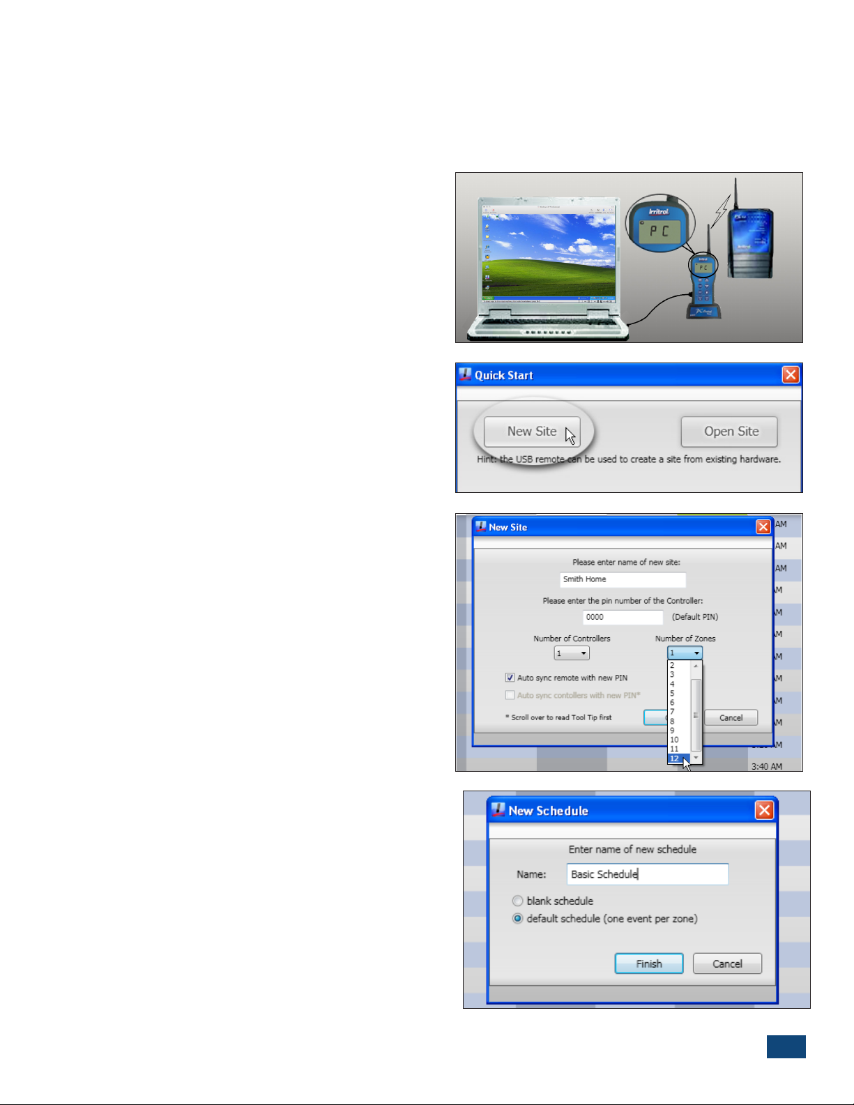
3. Using the provided USB cable, connect the PC-R to
the computer’s USB port.
The PC-R will display PC when the connection is
established (Figure 1.1).
4. From the Start menu, launch the PCW Control
program.
5. At the Quick Start dialog box, click the New Site
option button (Figure 1.2). The Open Site option is
used to open a previously saved site conguration
le.
Figure 1.1
Figure 1.2
Note: A “Site” le species how the PCW Control
system is congured. A Site requires a name, a PIN
code, the number of Controllers in use (1–4), and the
initial number of zones to be included in the operating schedule.
6. At the New Site dialog box (Figure 1.3), enter the
preferred site name.
7. In the PIN number eld, you may leave the default
0000 PIN code, or enter a preferred four-digit PIN.
(See Change PIN section, below).
8. The default number of controllers is one. If your
site utilizes more than one controller, select the applicable number from the drop-down list.
9. Select the number of zones to be scheduled. The
available zone count in the drop-down list will correlate with the number of controllers selected .
10. Click the OK button to save the Site le.
11. At the New Schedule dialog box (Figure 1.4), enter
your preferred Schedule name.
• A Schedule congures PCW Control system opera-
tion based on the active day(s), start time(s), and
Figure 1.3
Figure 1.4
PCW Control S Installation
3
Page 6
run time duration assigned to each zone.
• Any number of schedules can be dened and saved
to memory for later recall, however every schedule
must have a unique name assignment.
13. Select the Default Schedule option to open the
new schedule with a run time Blank Schedule to
start without presets.
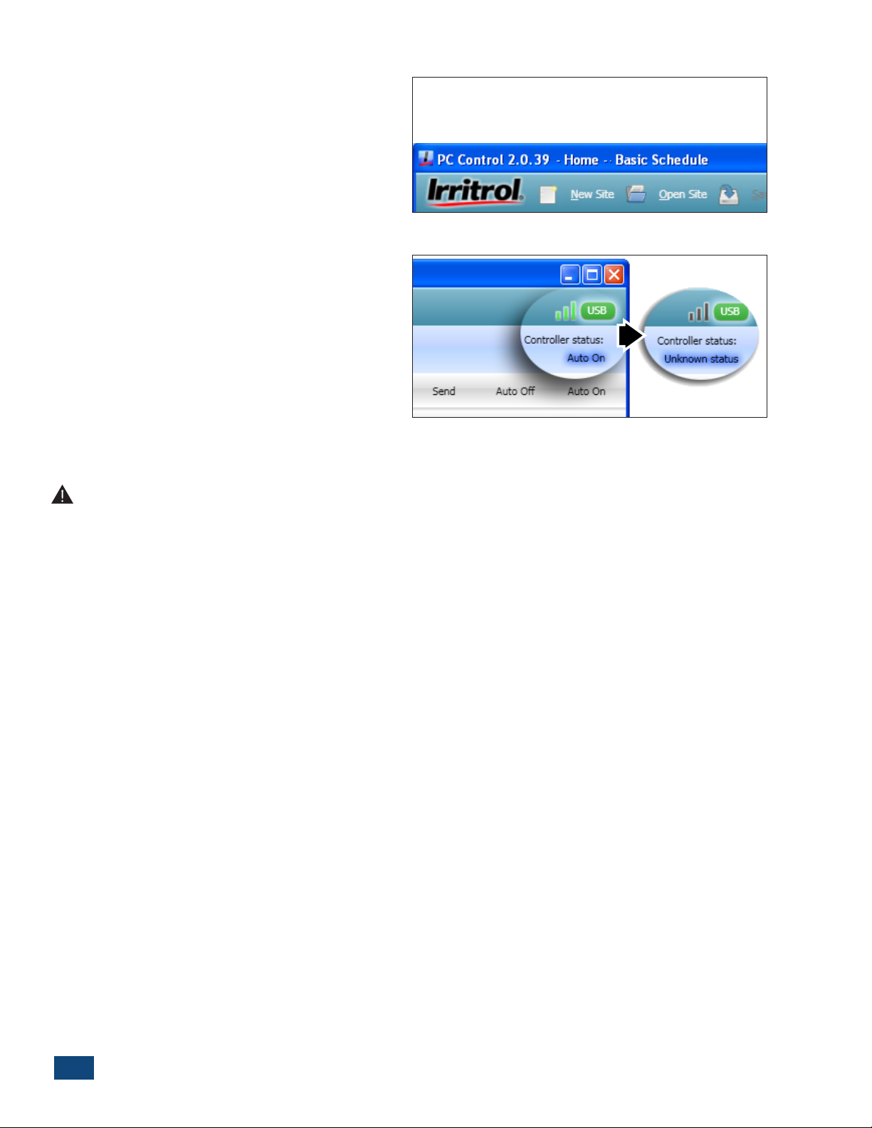
14. Click the Finish Button.
• The site and schedule name will be displayed at
the top of the program window (Figure 1.5).
The PCW Control program should begin communicating with the Controller(s) at this time and will activate
the control system; indicated by green signal bars and
the Auto On controller status. If a communication link
is not established, Unknown Status will be displayed.
(Figure 1.6) This condition is usually caused by a
mismatching PIN. Verify the PC-R and Controller have
a matching PIN and the Controller(s) can be operated
manually with the PC-R.
Change PIN
Figure 1.5
Figure 1.6
Important PIN Information: As a security measure, the PC-Remote (PC-R) and Controller utilize a
four-digit PIN code to enable wireless communication. Both units are initially set to 0000 by default. This
is an optional feature and can remain 0000 if desired. If you wish to change the PIN to prevent unintended
system operation, read this section.
Changing the system’s PIN can only be done from the computer when all the PINs are the same to begin with.
The parts of the system, computer, PC-R, and Controller all have to be communicating for “Change PIN” to
function. In the case of mismatched PINs (and in the case of multiple Controllers in the system), the PIN and
controller number need to be set manually in each controller. See the procedure below:
1. On the front of the Controller, press the “MANUAL” and “AUTO ON” buttons simultaneously to start the
“POWER” light blinking and illuminate one of the station lights.
2. With the station lights 1 thru 9 representing PIN digits 1-9 and with 10 representing “0”, use the “MANUAL”
button to advance to and illuminate the rst digit desired for the PIN.
3. Press “AUTO ON” to move the light down from “POWER” to illuminate “SIGNAL”. The “SIGNAL” light represents
the second PIN digit. Again, use the “MANUAL” button to move to and illuminate the second, desired PIN
number and then press “AUTO ON”.
4. Repeat the above steps to set the third and fourth PIN digits with “SENSOR” and “MASTER VALVE / PUMP”
illuminated respectively.
5. The last digit, represented by the “TEST” light, is for the controller or Controller number. If there is only one
controller in the system, set or leave the controller number at “1”. If setting up a second controller for the
system, use the “MANUAL” button to move to #2 in the “STATION” lights. The controller number selection
only goes up to four.
6. Hold down the “AUTO ON” button until the lights start a sequential display and then release the button. The
Controller will demonstrate what was set for each of the four PIN numbers and the controller number and
will then return to AUTO mode on its own.
PCW Control S Installation
4
Page 7
Chapter 2 - PCW Control Program Window Overview
The PCW Control program is designed for ease of scheduling, review and system operation. The
program window is organized so you can easily setup and review operating schedules, access the
weather data, fine-tune system operation, and manually operate the system as needed.
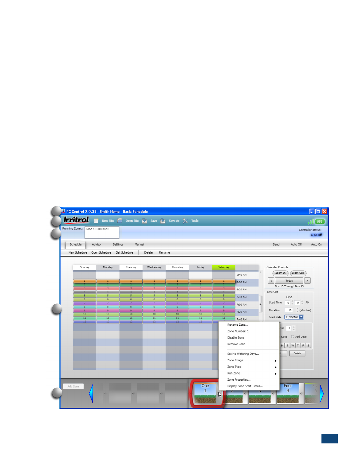
The program window is comprised of five main sections, shown below (Figure 2.1).
A – The dark blue title bar provides the PCW Control application version, currently open site and
schedule names, and the minimize/maximize/close window buttons.
B – Directly below is the turquoise Site Menu bar that provides direct access to the site resource
folders, save options and system tools. The PC-R remote USB connection and signal strength bars
are located on the far right.
C - The light blue section displays current Controller Status information including zone operation,
Auto On/Auto Off status, and system activity status.
D – The four main panel tabs of the light gray center section include the Schedule Viewer with Calendar Control center, schedule Advisor, Settings and Manual operation panel.
Located on the right are the Send, Auto Off and Auto On system control buttons. Below the Schedule tab are five schedule function buttons used to create a New schedule, Open a saved schedule,
Get Schedule (from Controller), and delete or rename a schedule.
E – The Zone Buttons are arranged across the bottom of the window. Each color-coded button is
linked to the corresponding colored/numbered zone segments in the Schedule Viewer. Modifications to individual zones are made through the Zone Button pop-up menu.
A
B
C
D
E
Figure 2.1
PCW Control S Installation
5
Page 8
The PCW Control Schedule Viewer
The Schedule Viewer (Figure 2.2) is the primary panel where the scheduled operation of each zone
is established. The Schedule Viewer is arranged in a 7-day calendar format that initially displays
the schedule for the number of zones specified in the New Site dialog box. Each zone has a specific
color and number assignment that corresponds to the Zone Buttons at the bottom of the window,
and to the field output terminals of the Controller. When the default schedule is selected in the
dialog box, each zone will be scheduled to run for 10 minutes, every day, beginning at 6:00 a.m.
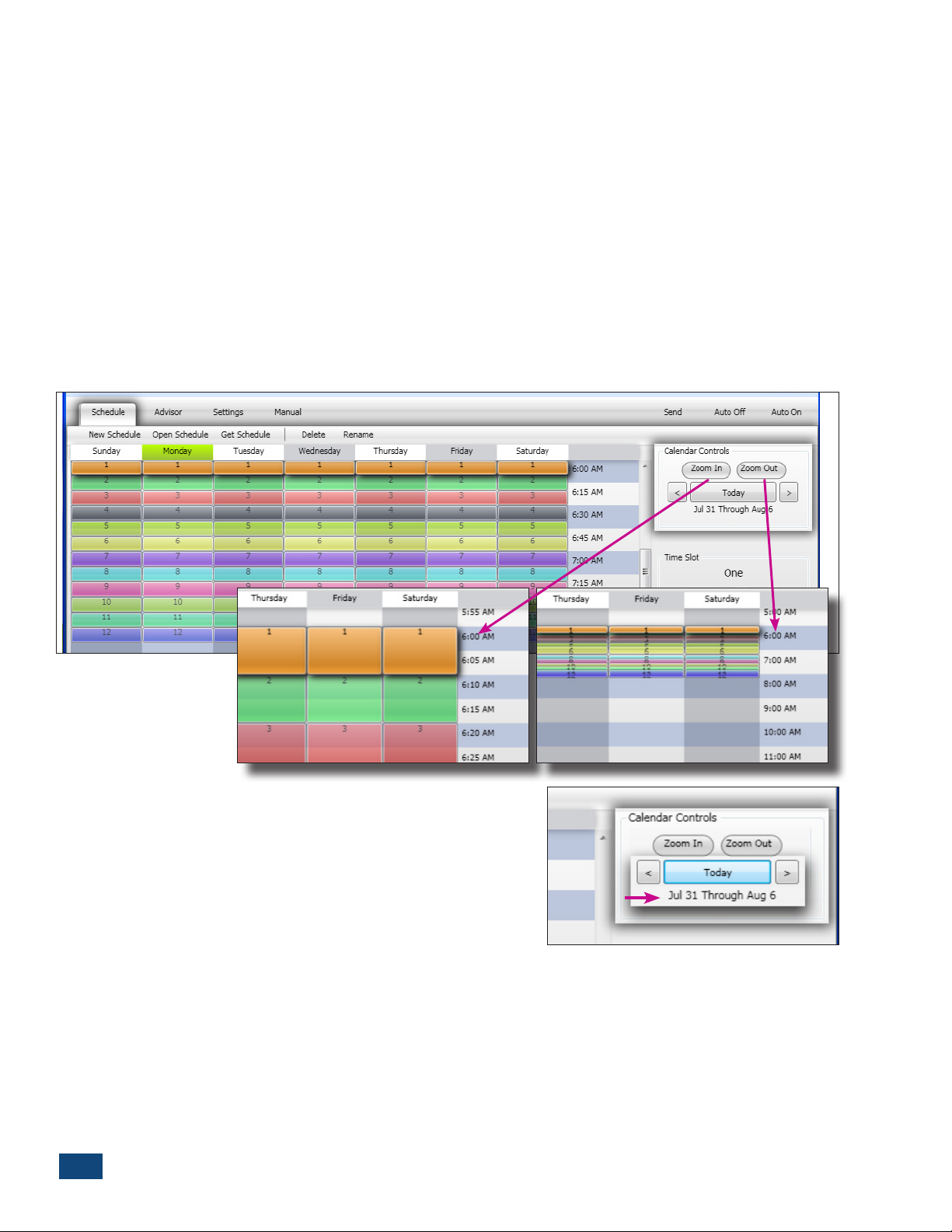
Calendar Control Panel
The Schedule Viewer is formatted with the days of the week arranged in columns starting on
Sunday, and Start Times arranged in rows, starting at 12:00 a.m. (Midnight). By default, start time is
displayed at a 30-minute increment resolution. The Zoom In and Zoom Out buttons enable the start
time resolution to be zoomed in to 5-minute increments, or zoomed out to a 1-hour increments.
Weekly
Figure 2.2
Calendar View
By default, the 7-day schedule will coincide with the current
date, verified by calendar dates displayed below the Today
button. The right and left arrow buttons are provided to
shift the schedule view forward and backward through the
calendar in 1-week increments. Selecting the Today button
resets the Schedule Viewer back to the current calendar week.
PCW Control S Installation
6
Page 9
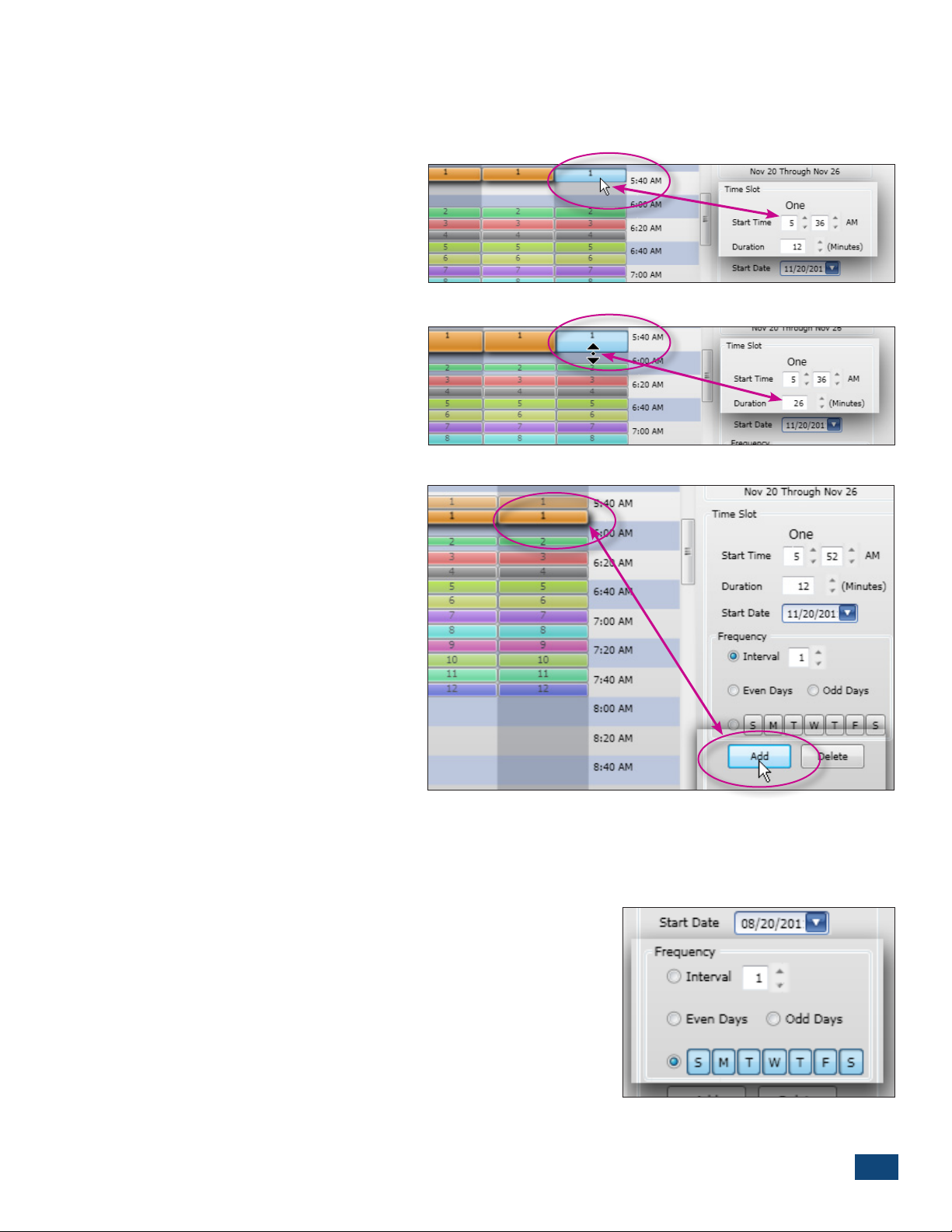
The Time Slot Editor
The zone Start Time and Run Time Duration can be configured directly within the Schedule Viewer,
or by selecting the desired values in the zone Time Slot editor.
To change a zone start time directly in
the Schedule Viewer, place the cursor over the desired zone segment to
highlight, then click and drag the segment to the desired start time (Figure
2.3).
To adjust the run time duration, place
the cursor on the bottom edge of the
segment, then Click and drag to adjust
the run time duration, (1–1400 minutes) (Figure 2.4).
To apply additional start times to a
zone, press the Add button (Figure
2.5). Each zone can have a maximum
of 10 start times. Remove a highlighted
start time by selecting the Delete button.
Note: By default, zone operation is limited
to one zone operating at any given
time. An Overlap Limit preference on
the Settings panel enables up to two
additional watering zones to operate
simultaneously.
See Site Settings Panel, p. 11, for
complete information.
Figure 2.3
Figure 2.4
Figure 2.5
Operating Day Schedule
The Operating Day schedule (Figure 2.6) determines which days a zone will be active. When the
default schedule is selected, all zones are scheduled to operate every day of the week, (based on a
1-day Interval schedule). Each zone operates independently and can be assigned to any one of the
following scheduling options:
•IntervalSchedule–Askip-dayfrequency,rangingfrom1–31;
where 1 equals every day, 2 equals every-other-day, etc., up
to one day every 31 days.
•Even- or Odd-Date Schedule – Schedules all even or odd cal-
endar dates as active watering days.
•Weekday Schedule – Schedules operation by days of the
week.
Note: Each zone can have only one operating day schedule. All
start times assigned to a zone are assigned to the same
operating day schedule.
PCW Control S Installation
Figure 2.6
7
Page 10
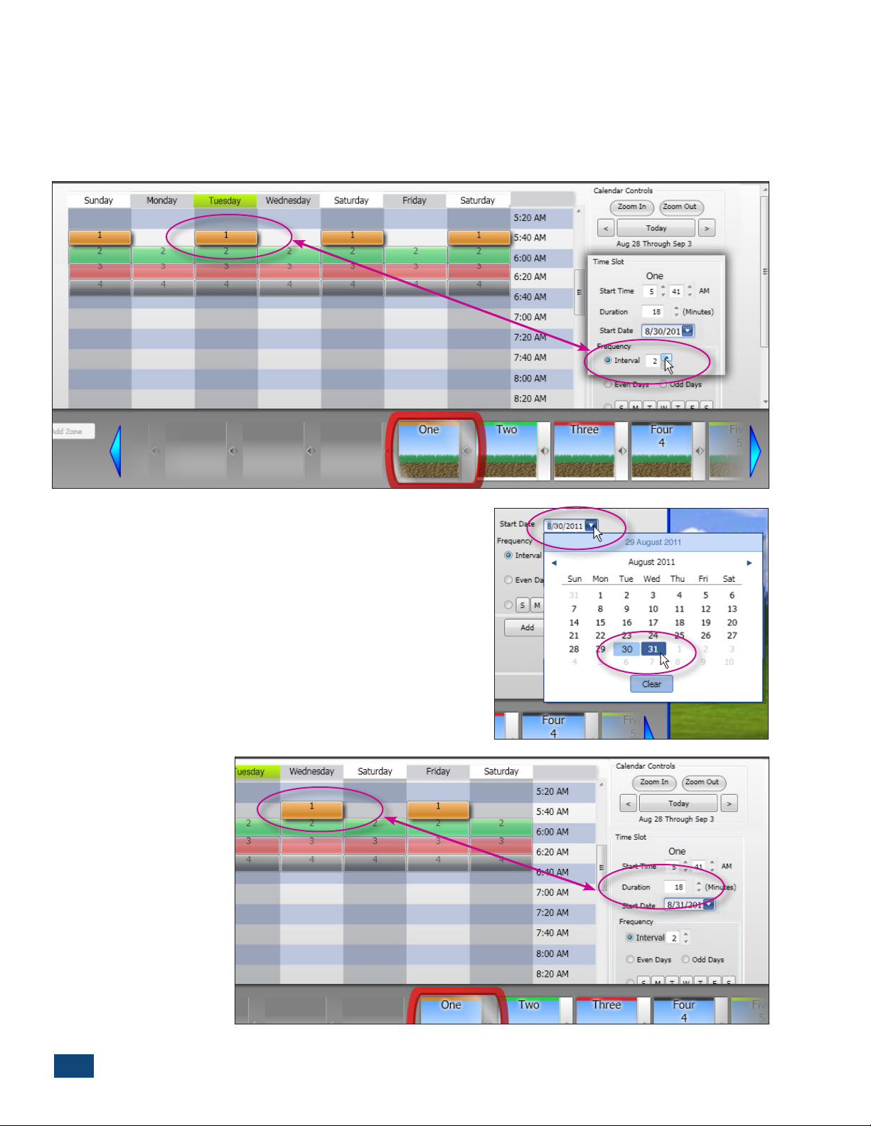
The Interval Schedule
To set an Interval schedule, highlight the zone by clicking on a segment bar, or on the corresponding Zone Button. Select the Interval option in the Time Slot editor. Use the up/down arrow scroll
box to select the preferred frequency (1–31) (Figure 2.7). Note the arrangement of the zone segment bars in the Schedule Viewer as the Interval frequency is changed.
Figure 2.7
To select an alternate Interval start day, click on the blue
down-arrow box to display the drop-down calendar. The
current Interval start date will be highlighted in dark blue.
Click on the preferred start date.
The new start date will be highlighted in dark blue and the
original start date will be highlighted in light blue (after the
calendar window is closed and reopened). Note the placement of the zone segment bars as the Interval start date is
changed. As shown in the screenshot (Figure 2.8) the start
date of the 2-day Interval has been changed from Tuesday
to Wednesday (Figure 2.9).
Figure 2.8
PCW Control S Installation
8
Figure 2.9
Page 11

The Even or Odd Date Schedule
Setting an Even- or Odd-date schedule is done in the same manner as setting an Interval schedule.
Simply select the corresponding button to choose the frequency schedule (Figure 2.10).
Note that in this Odd-day schedule, Wednesday and Thursday will be active. This circumstance will
occur at the end of all months with 31 days.
Figure 2.10
The Weekday Schedule
The Weekday schedule enables any day of the week to be selected as active. When initially selected
with the weekday button, all days are active. Click on the days of the week to remove them from the
schedule.
Figure 2.11
In the example above, a Weekday schedule has been selected for Zone 1 with Sunday and Friday as
non-operating days (Figure 2.11).
PCW Control S Installation
9
Page 12

The Zone Buttons
The individual Zone Buttons, located in the tray below the Schedule Viewer, are linked to the corresponding Zone Schedule bar segments. In addition, the zone configuration properties are accessed
through the Zone Button pop-up menus.
A zone must first be selected to enable it to be edited. Clicking on a
Zone Segment or the corresponding
Zone Button will position the Zone
Button into the Edit Frame. If a Zone
Button is not visible in the tray, clicking on the left or right blue arrow
buttons will scroll the Zone Buttons
into view. (Figure 2.12)
Figure 2.12
Adding Zones
Each site can schedule up to 12 zones.
If the site currently has less than 12
zones, selecting the Add Zone button
will open the Add New Zone dialog
box (Figure 2.13). All of the basic zone
setup properties can be applied to
the new zone through the dialog box.
The next zone in numeric sequence
will be added.
The default zone setup properties can
be changed as desired, including the
zone name, number, type (Water or
Lighting) and the Zone Box image
(Figure 2.14).
Click OK and the new zone will be
added to the Zone Box tray
(Figure 2.15).
Note: Refer to Time Slot Editor on page
2 to add a zone start time.
Figure 2.13
Figure 2.14
Figure 2.15
10
PCW Control S Installation
Page 13

Selecting Water Zone Properties
The Zone Properties configuration
menu is accessed by double-clicking
the preferred Zone Box. A specific set
of properties is provided for watering
and lighting applications. By default,
3
2
4
5
6
the zone property menu for watering
application will be displayed
1
(Figure 2.16).
(1)
Type – All zones are designated for
irrigation by default. To designate the
zone for landscape lighting, select the
Light button in the Type option box.
7
Note: For additional Lighting zone
setup options, continue at “Selecting
Lighting Zone Properties” on the
following page.
(2)
Zone Number – Enables the default
Figure 2.16
zone number to be reassigned to any currently unused zone number. The drop
down menu will list all currently available zone numbers.
Note: The default zone numbers corespond to the station output terminals in the controller
regardless of Zone Box content.
(3)
Name – Enables the zone to be labeled as preferred.
Note: Changes in the Zone Properties menu will not be reflected in the program until the
OK button has been selected.
(4)
Master Valve / Rain Sensor – Enable / disable the Master Valve / Pump circuit and/or
Rain Sensor for the zone as preferred.
(5)
No-Watering Days – Enables zone operation
to be restricted on specific days of the week. The
restricted days will be represented in the Schedule
Figure 2.17
Viewer with a striped segment (Figure 2.17).
(6)
Seasonal Adjustment – Changes the individual
zone run time duration (as indicated in the
Schedule Viewer) by a percentage value ranging
from 100% (unadjusted value) up to 200%, or
down to 10% in 5% increments.
(7)
Change Image – Enables the Zone Button
background image to be changed as desired. An
alternate image can be selected from the dropdown menu, or imported directly from your
computer by selecting the Custom option (Figure
2.18). The “My Pictures” folder opens when the
Custom button is clicked.
Figure 2.18
PCW Control S Installation
11
Page 14

Selecting Lighting Zone Properties
The Zone Properties configuration
menu is accessed by double-clicking
the preferred Zone Box. A specific set of
properties is provided for watering and
lighting applications. By default the zone
property menu for watering application
will be displayed (Figure 2.19).
(1)
Type – To designate the zone for a
lighting, select the Light button in the
Type option box.
(2)
Zone Number – Enables the default
zone number to be reassigned to any
currently unused zone number. The
drop down menu will list all currently
available zone numbers.
(3)
Name – Enables the zone name
label to be changed as preferred.
Note: Local ZIP code must be entered in
the Advisor Panel to enable the Sunset/
Sunrise lighting zone option. See “The
Scheduling Advisor Panel” on page 9 for
details.
3
2
4
5
1
Figure 2.19
(4)
Use Sunset Time to Start – Select this option to automatically begin lighting zone
operation at sunset (based on local ZIP code).
(5)
End Time – Select the Use Sunrise button to automatically end lighting zone operation
at sunrise. Select the Custom button to enter a
preferred end time.
(6)
Change Image – Enables the Zone Button
background image to be changed as desired. An
optional image can be selected from the dropdown menu (Figure 2.20), or imported directly
from your computer (“My Pictures” folder) by
selecting the Custom option. Simply double-click
the desired image from “My Pictures” and click
“OK” twice.
Note: The following image file formats can be
imported: jpg, jpeg, png, bmp, and gif.
Figure 2.20
12
PCW Control S Installation
Page 15

Zone Control Options
The Zone Control Options menu is accessed by
clicking on the gray bar, located on the right
side of the Zone button.
The Zone Control Options menu provides
an alternate selection path to access
specific zone property options. Additional
Zone Control options provided on this
menu included: Disable Zone, Remove
Zone, Run Zone, and Display Zone Start
Times (Figure 2.21).
Disable Zone: Select this option to disable
the zone from operation. Toggles the zone
off and on as needed, without deleting
the zone setup. The corresponding zone
segment will be grayed out and the control frame labeled nonoperation as illustrated at right.
Figure 2.21
Note: The Zone Properties menu is only
accessible through the Zone Control Options
menu when the zone is in the disabled mode.
Remove Zone: Removes the Zone Button
and all information for the zone from the
Schedule.
Important: When a zone is removed
from the schedule, it can be added back in,
but will be last in the Zone Button tray.
Run Zone: Enables the zone to be operated
manually for a selected or specified run
time duration (Figure 2.22).
Note: Once the zone has been started
manually, it can run to completion or can be
terminated at any time by selecting
Auto Off>Auto On or Manual>Stop.
Display Zone Start Times: Provides
an overview of the current start time
assignments for the selected zone. To edit a
start time, click the start time to highlight,
select Edit to display the Zone Start Time
edit box. Enter the preferred start time and
click OK (Figure 2.23).
Figure 2.22
Important: Zones assigned to the
Scheduling Advisor cannot be edited under
“Display Zone Start Times”.
Figure 2.23
PCW Control S Installation
13
Page 16

The Scheduling AdvisorTM Panel
The Scheduling Advisor is a powerful setup tool that automatically creates an effective watering
schedule based on specific sprinkler system and landscape parameters, in addition to local weather
factors retrieved from the internet.
The upper half of the Advisor panel provides convenient drop-down menus to select five specific
watering zone properties. Located to the right of the menus is the Advisor ET Adjustment slider, and
Earliest Advisor Start Time setting (Figure 2.24).
1
4
3
2
5
Figure 2.24
(1) Select the appropriate Advisor setting for each of the following characteristics:
• Sun Exposure – Full Sun, Part Sun, Part Shade, Full Shade or Custom (by % of exposure)
• Sprinkler Type – Single-Stream Rotor, Multiple-Stream Rotor, Fixed Spray, Drip, Bubbler, Microspray,
or Custom (by precipitation rate).
• Plant Type – Grass, Planter, Shrubs, Trees, or Custom (by plant root depth)
• Ground Slope – None, Low, Medium, or High
• Soil Type – Sand, Loam, or Clay
(2) Use Advisor check box must be selected to apply the Advisor-defined zone schedule.
(3) Advisor ET Adjustment: Use the adjustment slider to increase/decrease overall watering applica-
tion rate of an Advisor-based schedule.
(4) Earliest Advisor Start Time: Restricts the Advisor from scheduling a watering operation before a
specified time of day. By default, the earliest start time is set at 6:00 a.m.
(5) Weather – The specific weather information required by the Scheduling Advisor is entered in the
lower half of the panel. The local ZIP Code or City name is entered, and the current weather information is retrieved by selecting the Get Forecast button. If multiple site locations are to be used,
select the Add to Favorite Locations option. The selected locations will be retained in the Favorite
Locations drop-down list, and can be reinstated or removed as preferred. The Update Schedule
option enables the watering schedule to be automatically updated via the internet on a daily,
weekly, monthly or seasonal basis, with or without prior notification. Click the “Get Forecast” button
at the time of day you want the system to retrieve the weather data from then on (set for a time of
day that your computer is usually on).
14
PCW Control S Installation
Page 17

Advisor-Based Schedule
The watering schedule created by the Advisor is described on the Advisor panel and depicted in the
Schedule Viewer (Figure 2.25).
Figure 2.25
Note: The “Advisor” icon will be displayed in the lower corner of a Zone Button when the Scheduling
Advisor is controlling the zone watering schedule. The Use Advisor option must be unchecked to remove
or modify the Advisor-based zone schedule.
PCW Control S Installation
15
Page 18

The Site Settings Panel
The Site Settings panel provides an array of control options specific to the site configuration
(Figure 2.26).
Note: In order for any site configuration change to take effect, the Apply button and Send tab must be
selected. You will be prompted to save the site change(s) during the Send process.
Figure 2.26
Selecting Site Configuration Options
(1) Change PIN – The current PIN code can be changed as preferred using the Change
PIN option. The current PIN code assigned to the site will be indicated in the Change PIN dialog box
when opened (Figure 2.27). Type in a different four-digit PIN and select either of the following PIN
Options as preferred:
• Remote and Controller: (PINs must already
match to use this option.) This is the most
common selection when changing the PIN
code. Choosing this option changes the PIN
code in both the PC-Remote and the Controller
– ensuring that communication between the
components will not be lost.
• Remote Only: This selection changes the PIN
code in the PC-Remote only, and is generally
used by contractors when access to multiple
PC-Control irrigation systems is required.
(2) Hardware Information – Click to review
current controller hardware information
Figure 2.27
including firmware and hardware version,
model number and serial number.
16
PCW Control S Installation
Page 19

(3) Site Settings: Add/Remove Controller –
Manage multiple controller operation and
rain sensor input within this section of the
Settings panel. A check box is provided to
1
enable/disable up to four controllers per
site. Each additional controller increases
the displayed zone count in Controller 1
up to 12 zones, for a maximum a total of 48
3
2
zones.
• Rain Sensor Options – Also included
in this panel section are the Rain Sensor
configuration options. To utilize an auxiliary rain sensor with Controller 1, the Use
Rain Sensor box must be selected and the
rain sensor hardware must be connected to
the controller.
4
5
Note: When the rain sensor option is selected,
all zones will be assigned to the rain sensor
control, as indicated by RS in the lower right
corner of each Zone Box (Figure 2.28)
Figure 2.28
To isolate a zone from rain sensor operation,
such as watering areas not exposed to rainfall, deselect the rain sensor option within the individual
Zone Properties menu.
In systems where multiple controllers are utilized, the rain sensor connected to Controller 1 can be
linked electronically to each additional controller by selecting the Remote option. If an additional
controller has a dedicated rain sensor connection, select the Local option for that controller.
Note: The Rain Sensor option is selectable by zone within the Zone Properties menu, but must first be
enabled in the Site Settings panel to become available within the individual zone setup menu.
Note: Some of the selections in the Settings panel must be
saved and uploaded to the controller site to become effective. Selecting the Apply button followed by the Save and/
or Send button is required each time a selection is made.
(4) Overlap Limit – By default, the controller is restricted to operate one zone at a time, regardless
of the watering schedule. If the irrigation supply source is capable of providing sufficient capacity
to operate more than one watering zone at a time, the Overlap Limit can be set to enable up to two
additional zones to operate simultaneously. “0” equals no overlap, one zone at a time.
Caution: The maximum field output is 24 VAC, 0.4A per station, with a combined total not to
exceed 1.0A (including a master valve or pump start relay and zones designated for lighting).
Exceeding this limit will activate the controller’s automatic circuit breaker to restrict field
output.
(5) Rain Delay – Automatic controller operation can be manually set to prevent watering from 1 to
7 days by moving the sliding pointer to the right. Automatic operation will resume at the end of the
delay period, or can be reinstated at any time by moving the slider back to the left stop. (Not for use
with a rain sensor.)
PCW Control S Installation
17
Page 20

Note: The PCW Control program offers a variety of seasonal adjustment options that can be applied
globally to the Site and/or Schedule and/or individually to each zone. The percent adjustment for
seasonal changes are for systems not using Scheduling Advisor. Refer to Appendix 2– Advanced
Adjustment Features for detailed information
regarding Seasonal Adjustment options.
6 8
(6) Global Seasonal Adjustment is used to
apply a seasonal adjustment % factor globally to
any Schedule opened within the Site.
A % adjustment value, ranging from 100%
(unadjusted value) up to 200% or down to 10%
in 5% increments, can be applied globally to all
months of the year or to each month individually
as preferred. For individual months, select the
9
month’s radio button, then adjust the slider to
the % value as preferred. (Figure 2.29)
Each month selected will retain its corresponding adjustment % value after the selections have been applied, saved and sent to the
7
controller.
Note: When the All 12 Months option is selected,
the adjustment value will change to 10% (by
default) for all months. Be sure to set the adjustment slider to the preferred % value.
(7) Advanced Seasonal Adjustments enable
seasonal adjustment factors to be applied to
specified controllers (in multiple-controller
applications), to all zones or individual zones
within a schedule.
Note: A seasonal % value adjustment applied to
a zone within the Zone Properties configuration
menu will be reflected in the Advanced Season
Adjust Settings menu and vice-versa.
(8) Global No-Watering Days – Enables individual days of the week to be restricted from
operation for any schedule opened within
the site to comply with local water restrictions.
(9) Water Restriction Time – Enables a specific
window of time to be established that will
restrict all automatic watering operation. By
Figure 2.29
selecting the Use Restriction Window option,
the restriction window Start Time and End Time
can be established.
Note: When setting the Start Time and End Time, make sure the appropriate AM/PM reference is
displayed.
18
PCW Control S Installation
Page 21

Manual Operations Panel
1
3
2 4
Figure 2.30
Multiple-zone manual watering program are formatted and controlled in the Manual Operation Panel
(Figure 2.30).
(1) Multi-Manual Presets – Preset manual watering programs that the user creates are listed by
name in the drop-down menu for easy access and operation. The New and Delete buttons are used
to add and delete preset programs as preferred.
(2) Multi-Manual Zone List – The Zone Button in the red Edit Frame will be added to the program
list by selecting the Add button. The order in which Zones are added and listed determines the
zone operating sequence.
(3)Duration – Each zone is assigned a manual run time duration of 1 minute by default, with an
adjustment range of 1 minute to 99 hours.
(4) Start/Stop Buttons – The Start and Stop buttons are used to initiate the preset watering
program. To terminate the watering program at any time prior to automatic time-out, press the
Stop button.
Note: The Stop button is also used to terminate a single zone manual watering operation initiated in
the Zone Control Options menu.
PCW Control S Installation
19
Page 22

Multi-Zone Manual Program Setup
• SelecttheNew button to open the Manual Preset Name
dialog box (Figure 2.31).
• Enteraprogramname,thenclickOK(Figure2.32).
• ThemanualprogramnamewillbeenteredintheMulti-
Manual Presets drop-down menu (Figure 2.33).
• SelecttheZoneButtonfollowedbytheAddbuttonto
format the manual watering program list. The zone order
selected will be the order of operation during the watering
program. Continue to add as many zones to the list as
preferred (Figure 2.34).
Figure 2.31
Figure 2.32
Figure 2.33
• Clickonthezonenumber/nametohighlight.Selectthe
amount of zone run time using the scroll arrows. Repeat
to assign a run time duration for each zone on the list (as
required) (Figure 2.35)
• Aftersetup,themanualprogramcanbeaccessedbyname
at any time and started.
20
PCW Control S Installation
Figure 2.34
Figure 2.35
Page 23

Chapter 3 – Hardware Features: PC-Remote and Controller Operations
The system’s handheld remote (Figure 3.1) is the primary way to manually send
commands to the irrigation controller. The remote has several uses
and features.
1. When connected to the computer, the remote relays the schedule changes and
manual commands, wirelessly, to the Controller.
2. When handheld and disconnected from the computer, the device can
remotely perform the following:
a. Turn any zone or station ON or OFF (irrigation or lighting zones)
b. Turn the entire system to automatic mode or to system OFF mode
c. Turn on all landscape lighting zones (up to three zones maximum
at a time)
d. Indicate Rain OFF mode because of a wet rain sensor (rain cloud icon)
e. Indicate signal strength with the antenna icon
f. To preserve battery life, the remote turns itself off after a few seconds
of button inactivity (or just hold down STOP until “OFF” appears).
To use the remote, unplug the cord’s USB mini-connector from the side
of the handheld unit and reinsert the captive plug to help prevent
water entry.
1. Wake up the remote by pressing any button for one second. All
elements of the display will illuminate for a moment and the then
“AUTO” should be displayed (if the controller it found with the
same PIN is in automatic mode) or “OFF” for off mode.
Figure 3.1
2. Turn any station ON by selecting it with the UP or DOWN button
and pressing START. Press STOP to stop the station. To advance or change from one running station or zone to start another, use the UP or DOWN arrow button to move from the current station
and select a new station number. The previous station or zone will turn off and the selected station will start. Remote or Manual starts override a wet rain sensor and irrigate.
3. A remotely started station has a 10- minute default run time. To change the run, press the SHUTTLE button (arrows pointing both right and left) to start the “10 Min” blinking and then reset the
time from 1 to 59 minutes (in 1-minute increments) or from 1 to 4 hours (in 0.1-hour increments).
The operating countdown starts immediately for the selected station.
4. A lightning bolt icon in the display indicates a short circuit on one of the zones. The shorted zone
light will be blinking on the front of the Controller. The cause of the short must be corrected, then
run the station remotely or manually to clear the short indicator.
5. To turn on all landscape lighting zones (3 stations max.) wake the remote and let it find the controller and then press the light bulb button. The lighting zones will turn on for a default time of 1
hour or pressing the light bulb button again will shut them off.
6. To set the remote’s PIN, wake the remote and then hold down the two, top buttons for 3 seconds
simultaneously. Four digits will appear. Use the UP or DOWN arrow button to set the first digit in
the PIN. Then use the shuttle button to move to the next digit to the right. Repeat the steps to set
the rest of the 4-digit PIN. Then press START. When the remote finds the Controller with the same
PIN, “PIN OK” will appear in the display, then “AUTO” or “OFF” depending upon the Controller’s
mode.
PCW Control S Installation
21
Page 24

Chapter 4 – Remote Master Valve / Pump Start Feature
The Remote Master Valve / Pump Start Feature is only for systems with more than one controller.
A Master Valve (MV) is an automatic valve that shuts off the water supply pipe when the irrigation
system is idle. The master valve reduces the chance of flooding from a zone valve that leaks or has
failed while open. The controller turns on the MV when it turns on the first valve in a program and
turns off the MV when the last valve has timed out.
A Pump Start circuit is a circuit designed to energize a Master Valve or to operate a pump start
relay(24-volt AC). It allows a power source (120 VAC, 220 VAC, etc.) to connect to a pump motor. Like it
does for a master valve, the controller switches the pump on with the first station and off again once
the last valve closes.
For irrigation systems with one main supply line and multiple controllers, the Remote MV / Pump
Start feature allows the other controllers to use the master valve / pump start circuit on Controller
Number 1. This saves wire and trenching for multiple pump start circuits. In the system, each
controller (2, 3, or 4) is provided the choice of using itw own pump start circuit or that of controller
#1. In the same way, if controller #1 has a rain sensor, clicking the “Remote” radio button in controller
#2’s “Rain Sensor” box tells controller #2 to use controller #1’s rain sensor.
Below, the installer has set Controller #2 to use the master valve of Controller #1 and its rain sensor.
22
Figure 4.1
PCW Control S Installation
Page 25

Appendix 1 – Frequently Asked Questions
Q: What is the AdvisorTM?
A: The Advisor is a unique PCW Control program feature that will automatically formulates a zone watering
schedule based on specic parameters including, sun exposure, sprinkler type, plant type, terrain slope, and
soil type. Observed weather factors, including, temperature, humidity and wind condition can be entered as
well, or the local 9–10-day weather forecast, based on city name or ZIP code, is retrieved from weather.com
and factored into the schedule. The formulated schedule is then transferred to the Schedule Viewer panel.
Q: What weather data is used by the Advisor?
A: This version of the PCW Control software accesses data from a proprietary weather service. You can choose
to automatically update the weather data daily, weekly, monthly, seasonally, or never.
Q: Will the system shut o during rainfall?
A: The Controller is sensor-ready and compatible with most auxiliary rain or rain/freeze sensors. Irritrol rain
sensors are recommend and are available in three models: RS1000 - wireless rain sensor,
RFS1000 - wireless rain/freeze sensor, and RS500 - wired rain sensor. (Use of a sensor is recommended.)
Q: Can the system save water?
A: Yes, there are several ways the system can save water:
•Thesystemcanbeshutdownforthewintermonthsfromtheconvenienceofyourcomputer.(Infreezing
climates, this does not replace “winterizing” the system with compressed air blow-out.)
•TheschedulingAdvisor™willsavewaterbyadjustingtheirrigationscheduleperweatherconditions.
•Anoptimalrainsensorwillshutoirrigationduringadownpour.
Q: What PCW Control system components can be added or replaced?
A: The following PCW Control system components are available from your Irritrol distributor:
12-Station Indoor Controller w/Remote and Software Model# PCW-12 INT-PAK
12-Station Add-on Indoor Controller Model# PCW-12 ADD-INT
12-Station Outdoor Controller w/Remote and Software Model# PCW-12 EXT-PAK
12-Station Add-on Outdoor Controller Model# PCW-12 ADD-EXT
PC-Remote w/Stand, USB Cable and Software Model# PCW-R
The following service parts are also available:
Kit, Service Panel, Lower P/N 102-4973
Transformer, External, 115-120V, Outdoor Controller P/N 102-4788
Transformer, Internal, 115-120V, Indoor Controller P/N 363-4574
Kit, Service Door, Outdoor Controller P/N 102-4974
Q: Can I access my PCW Control irrigation from work or while traveling?
A: You can use a remote-access application, such as, GoToMy PC
computer from any other Internet-connected computer. As long as the PC-Remote is connected to your home
computer, you will have complete access to your PCW Control system.
®
that enables you to access your home
PCW Control S Installation
23
Page 26

Q: What’s the best way to get technical support?
A: Contact Irritrol Customer Support by phone at 1-800-634-8873, weekdays 7:30 a.m.–4:00 p.m., PST, or via
e-mail at: pccontrolsupport@irritrol.com. Visit the Irritrol Systems website at www.irritrol.com/pccontrol for
product support information.
Q: Why does it matter if a zone is designated for water or lighting?
A: When a zone is designated for lighting control, the optional watering control features; such as, rain sensor,
master valve/pump start, and scheduling Advisor options, are not factored into the zone operation. In addition, the PC- Remote handheld provides separate operating controls for watering and lighting zones.
Q: Do I set up a water feature as water zone or a lighting zone?
A: A fountain or water feature should be designated as a lighting zone, since the optional control features provided for irrigation would not be applicable. Make sure the controller station output is not connected directly
to the water pump. A 24 VAC relay rated at 0.4A maximum must be used. The Irritrol SR-1 relay unit is designed
for this type of application.
Q: How does the contractor change the homeowner’s PIN? Does it require a PC or can it be
done using just the remote?
A: To change the PIN, the contractor must know the old PIN and use his laptop with the PC remote to change
the PIN.
Q: How do I know what software version I have?
A: The software version is shown in the top left corner of the program window. You can also access the system
information by selecting Tools>About from the main menu.
Q: How do I know if I have the latest version of the software?
A: If you have registered your PCW Control system with Irritrol, you will receive a notice when an updated ver-
sion of the software is available.
Q: How many schedules can you have in the program? If you’re a contractor, how many
customer schedules can you save?
A: Currently there is no limit on how many schedules you can have at one time.
Q: Can you schedule a “no” irrigation day?
A: Yes, you have the option to prevent watering on any days of the week. (See No-Watering Days on page 18.)
Q: What happens if you have overlapping zone schedules
A: An overlap option is provided in the Settings panel that will enable you to schedule up to three zones to
run simultaneously. The defaut for this option is 0 overlap. Unless it is changed, a prompt will appear if you
attempt to schedule two or more zones to run at the same time. The overlap option is generally used to allow
lighting and irrigation zones to operate simultaneously.
Q: What is the maximum run time per station?
A: Each zone can be scheduled to run for 1 minute to 24 hours, in 1-minute increments.
Q: Does the controller supply power to the landscape lights?
A: No, the controller provides switching control for a 24 VAC relay with a maximum output of 0.4A per station.
The Irritrol SR-1 relay unit is designed to operate a pump starter or outdoor lighting control box from an irrigation system controller.
24
PCW Control S Installation
Page 27

Q: What if there is a power outage? Would everything still get watered?
A: The Controller will not operate the zones without 115/120 VAC. The “ash memory” in the Controller will
retain the current operating schedule indenitely in the absence of AC power. A fresh 9V battery will maintain
the current time/date for 48 continuous hours. Therefore, it’s recommended to change the battery at least
once a year–especially if the area is prone to frequent power outages. If the battery is dead (or is not installed),
the Controller time/date will be synchronized when contacted by the PCW Control computer program.
Q: If my computer goes down, can I still use the remote?
A: The last schedule uploaded to the Controller will reside indenitely in memory without being connected to
the computer. The system can be operated manually at any time using the hand-held Remote when disconnected from the computer.
Q: What if there is a power surge?
A: The Controller has built-in surge protection designed to divert strong electrical surges to earth ground.
Q: How do I know if there are any electrical short circuits?
A: A built-in electronic circuit breaker will shut down any eld output(s) when an over-current condition is
detected–generallycausedbyafaultyvalvesolenoidorashortedsolenoidwireconnection.Theoending
zone number(s) will be identied on the Controller with a ashing LED. The remaining zones will continue to
operate as scheduled.
Q: Can my system be reprogrammed even if my PC is down?
A: If you have your PCW Control system PIN, a professional irrigation contractor equipped with a laptop PC,
the remote, and the PCW Control program software can upload schedule changes to your control system.
Q: Can I transfer the PCW Control system setup to a new computer?
A: Yes. Install the software for the PCW Control system in your new computer, download your entire program
from the older computer to a CD or thumb drive, and upload that program (on the CD or thumb drive) to the
new computer. Use the current PIN to access your controller.
Q: How do I transfer my schedule information from an old computer to a new computer?
A: This is actually quite a lengthy process. See Appendix III for a detailed answer.
Q: I cannot change the PIN in my controller from my computer. The remote changed OK.
What should I do?
A: Unless all components (PC, Remote, and Controller) have the same PIN, the PIN in the controller cannot be
updated from the computer. (See the note at the end of Chapter 1.)
Q: Where do I nd an electronic version of the User’s Guide?
A: Click “Tools” and select “Help Manual”.
PCW Control S Installation
25
Page 28

Appendix 2 – Advanced Adjustment Features
There are multiple adjustment settings in the software.
1) Seasonal Adjustment, which can be individually set for each month (NOT if using Scheduling
Advisor)
2) Schedule Seasonal Adjustment, which adjusts all station runtimes on the current schedule
2) ET Adjustment, which adjusts the ET value used in scheduling calculations
4) Zone Seasonal Adjustment, which adjusts the selected zone’s runtimes
This appendix will discuss each setting in detail.
Global Seasonal Adjustment
The Global Seasonal Adjustment (Figure A2.1) will adjust all runtimes
in the system. The adjustment value is downloaded and stored in the
controller. The adjustment values for each month are independent
of the others. Once the calendar day rolls over to the next month the
controller will automatically start using the current month’s seasonal
adjustment value.
If you check the box “All 12 Months” the seasonal adjustment value will
drop to 10% (minimum value) to reflect that the user wants to set all
the months’ season adjustments. If you select an individual month then
the adjustment value will reflect the current seasonal adjustment on
that month.
Figure A2.1
Figure 2
Schedule Seasonal Adjustments
(Advanced Seasonal)
The Advanced Seasonal Adjust Settings allows the user
to modify a whole schedule or specific stations.
The Schedule Seasonal Adjustment (Figure A2.2)
affects all stations that have at least one event on the
current schedule. The adjusted runtime is a simple
multiplication of the percentage with respect to the
station’s runtime.
The Zone Seasonal Adjust affects all events for the
selected station. The adjusted runtime is a simple
multiplication of the percentage with respect to the
station’s runtime. The seasonal adjustment for each
station can be accessed through the Zone Properties
(Figure A2.3).
If there is more than one controller in the system,
change the “Select Controller” option to display the
selected controller’s stations.
26
Figure A2.2
PCW Control S Installation
Page 29

ET Adjustment*
The Advisor ET Adjustment (Figure A2.3) allows the user
to adjust the watering recommendations provided by the
scheduling advisor. The ET adjustment is NOT a simple
multiplication of the runtime. Instead, the adjustment
changes the ET value used to create the watering suggestions so a change of 10% in the adjustment might reflect
the advisor suggesting an increase of 20% to your runtime,
not a 10% increase.
If the Global Seasonal Adjustment is not at 100% the
Advisor will inform the user so that they can make more
accurate decisions when adjusting the ET value.
*(NOT compatible with Scheduling Advisor)
Working with Different Adjustments:
The user can affect the runtimes in various ways using
the different adjustment settings. In the example
below, each zone has a single watering event set
to run for ten minutes, and the global seasonal
adjustment set to 100%.
Figure A2.3
Figure A2.4
By changing the Schedule Seasonal Adjustment to
120% (Figure A2.4) the new runtimes for the stations
are twelve minutes.
Notice, that zone five is set to 115% for the Zone
Seasonal Adjustment. When viewing the schedule
zone five has a runtime of seventeen minutes, whereas
all the other stations have a twelve minute runtime
(Figure A2.5). This is consistent with the multiple
seasonal adjustments interacting with each other.
Figure A2.5
PCW Control S Installation
27
Page 30

Appendix 3 – Transferring Irrigation Schedules
It is possible to transfer irrigation schedule files from one computer to another. Irrigation schedule
files are XML files stored in a hidden folder on the hard drive of the host machine. If rights have not
been set to view hidden files and folders, that is the first step. Below are directions for Windows 7.
1. Set up View options to view hidden files and folders.
a. Double-click any folder icon to open a
Windows 7 window.
b. On the now visible window, click on the
Organize button (top left) (Figure A3.1).
c. Select “Folder and search options...”
d. Click the View tab.
e. In the Advanced Settings area, select
“Show hidden files, folders, and drives”
radio-button (Figure A3.2).
f. Click OK.
Figure A3.1
2. The default location for the XML file
installation is C:\Users\[login name]\
AppData. Navigate there.
If the AppData folder is not visible, go back
to step 1.
28
Figure A3.2
PCW Control S Installation
Page 31

3. Double-click the AppData folder, then
the Roaming folder, then the Irritrol
folder.
There is the default irrigation schedule
location.
4. Sweep all files in that window with your
mouse (Figure A3.3), copy (Ctrl-C), then
paste (Ctrl-V) them into a thumb drive
window.
5. Put the thumb drive into the new
computer.
6. Navigate to the same location on
this computer. C:\Users\[login name]\
AppData\Roaming\Irritrol.
If the AppData folder is not visible for this
computer, follow Step 1 for this computer.
7. Paste all files from the thumb drive into
this new window. “Copy and Replace” if
prompted.
Figure A3.3
8. Launch the PCW Control software and
click on “Open Site”.
9. All files should be present and ready to
use (Figure A3.4).
Figure A3.4
PCW Control S Installation
29
Page 32

Troubleshooting Guide
Symptom Possible Cause Solution
I have a new computer, or, I lost the
CD. Where do I get the software?
N/A Download the latest software at http://
www.pc-controller.com/PCW_Control.zip
How do I uninstall version 1.1.56 or
earlier?
My remote indicates there is no
communication when I turn it on.
All three signal bars in the software
are gray.
My remote displays “NO SIGNAL”
and “NOT ACCEPTED”.
The remote will not communicate
with additional controllers.
The remote displays “E1”. Most likely caused by a defective IC
The uninstall for versions 1.1.56 and
earlier does not work.
If the controllers are turned on
and match the PIN in the remote,
then most likely the cause is from
rmware.
Communication between the
software, remote, and controller(s)
is not working. Most likely the PIN
values do not match.
Controllerandremotehavedierent PIN codes.
Most likely caused by not manually
setting the additional controller’s
PIN and controller number.
in the remote.
Download our uninstall utility at http://
www.pc-controller.com/uninstall.exe.
When the remote is turned on, press the
top two buttons, side-to-side arrows and
the up arrow buttons. When your PIN is
displayed press the Start button. Your communication should be working now.
Check each hardware device and the PIN
value in the software to conrm that they
are the same.
See the Change PIN section in this User’s
Guide .
Check each controller and set the correct
PIN and controller number. All controllers
come from the factory set with PIN 0000
and as controller #1.
Please contact Irritrol Support for warranty
replacement.
Under “Display Zone Start Times”, I
highlight the start time but my edit
won’t change on the calendar.
The remote only displays 12 stations for a system that contains
multiple controllers and more than
12 stations.
Software displays “Invalid Data
Array” message when updating the
controllers.
The software displays “time out”
when sending a schedule or updating the controller(s).
Zones assigned to the Scheduling
Advisor cannot be edited in this
mode.
The main controller (controller #1)
has not been updated with the
additional controllers and station
information. This is the master controller of the system.
Possible invalid characters sent or
received from the controller(s).
Bad radio frequency interference in your environment, or the
controller(s) are too far away. The
range for communication is 1000
feet using line of sight. This will vary
depending on your environment.
Click on the Advisor tab, click on the zone
in question and then uncheck “Use Advisor”. Zone is now editable.
Open the XML le that you are using for
the multiple controller system, and after
establishing communication, update the
controllers by pressing the “Send” button.
Try pressing the “Send” button again. If the
message is still displayed contact Irritrol
Support so that you can send your XML le
for review.
If you have a laptop, move around your
property and see if you can establish a
more consistent connection. If you are using a desktop you can unplug the remote
anduseasimple“AutoOn/O”testby
walking around your property and conrming the communications are received by
the controller(s).
30
PCW Control S Installation
Page 33

Troubleshooting Guide (continued)
Symptom Possible Cause Solution
Where are my schedules and/or
les located?
The schedules are contained in the
XML les. Each XML le can contain
numerous schedules. You can save
these les to any directory, such as
My Documents.
Windows 7 - C:\Users\USER_ACCOUNT\AppData\Roaming\Irritrol
The software crashes or does not
respond when I open a le or when
using a default site.
The irrigation does not come on
according to the schedule shown
in the software.
I cannot click and hold the bottom edge of the zone segment to
change the watering duration.
I have most of my zones on the
Scheduling Advisor, and I have
checked “Update schedule changes without prompting”, but I do not
see scheduling changes with the
weather changes.
My system is using the Scheduling
Advisor, but keeps on watering
even when it’s raining.
Either the le you are trying to open
or the default le the software is
trying to open is missing some
information.
Most likely the controller(s)’ date
andtimeareo.
The zone is assigned to the Scheduling Advisor.
Thecomputeristurnedoatthe
time of day the system was told to
check the weather on the internet.
The internet weather is unaware of
local showers.
Open the le using MS Word or any other
text editor and see if there are any Schedules that are missing the <Events> tags. If
these schedules are present, then remove
them and save the le. If this does not work
then please contact Irritrol Support so that
they can review your le.
Under Tools->Preferences, click the option
to synchronize controller(s)’ time. Next, hit
the “Send” button in the software to update
the date and time in the controller(s).
To customize the zone, click on the ADVISOR tab, when the zone is highlighted,
uncheck “Use Advisor”.
Click on “Get Forecast” at the time you want
the system to regularly retrieve the weather
information. Make sure it is a time of day
your computer is on and connected to the
internet.
For the most water savings based on the
weather, we recommend the addition of an
Irritrol rain or rain/freeze sensor.
FCC Part 15 Rule
This equipment has been tested and found to comply with the limits for a Class B digital device, pursuant to Part
15 of the FCC Rules. These limits are designed to provide reasonable protection against harmful interference
in a residential installation. This equipment generates, uses and can radiate radio frequency energy and, if not
installed and used in accordance with the instructions, may cause harmful interference to radio communications.
However, there is no guarantee that interference will not occur in a particular installation.
If this equipment causes interference to radio or television reception, which can be determined by turning the
equipment on and off, the user is encouraged to try to correct the interference by one or more of the following
measures:
1. Reorient or relocate the receiving antenna.
2. Increase the separation between the equipment and receiver.
3. Connect the equipment into an outlet on a circuit different from that to which the receiver is connected.
4. Consult the dealer or an experienced radio/TV technician for help.
The user may find the following booklet prepared by the Federal Communications Commission helpful: “How
To Identify and Resolve Radio-TV Interference Problems”. This booklet is available from the U.S. Government
Printing Office, Washington, DC 20402. Stock No. 004-000-00345-4 s.
© 2012 Irritrol • www.irritrol.com • 1-800-634-8873 Form Number 373-0762 Rev. A
PCW Control S Installation
31
 Loading...