

Page 1
VALVE
COMMON
VALVE
COMMON
VALVE
COMMON
MASTER
VALVE
YEL RED
VALVE
COMMON
GND
1 3 5 7 9 11 13 15 17 19 21 23 25 27 29 31 33 35 37 39 41
2 4 6 8 10 12 14 16 18 20 22 24 26 28 30 32 34 36 38 40 42
1 3 5 7 9 11 13 15 17 19 21 23 25 27 29 31 33 35 37 39 41 43 45 47
2 4 6 8 10 12 14 16 18 20 22 24 26 28 30 32 34 36 38 40 42 44 46 48
M C-E
Installation Instructions & Programming Guide
For Controller Models: MC-4E, MC-6E, MC-8E, MC-12E, MC-18E,
MC-24E, MC-30E, MC-36E, MC-42E & MC-48E
English Español Français
Page 2

Table of Contents
Introduction -- -- -- -- -- -- -- -- -- -- -- -- -- -- -- -- -- -- -- -- -- -- -- -- -- -- -- -Pg. 3
Parts Diagram -- -- -- -- -- -- -- -- -- -- -- -- -- -- -- -- -- -- -- -- -- -- -- -- -- -- -Pg. 3
Cabinet Installation - -- -- -- -- -- -- -- -- -- -- -- -- -- -- -- -- -- -- -- -- -- -- -- Pg. 4
Electrical Conduits Installation - -- -- -- -- -- -- -- -- -- -- -- -- -- -- -- -- -- -- Pg. 4
Control Wires Installation -- -- -- -- -- -- -- -- -- -- -- -- -- -- -- -- -- -- -- -- -- Pg. 5
Rain Sensor Installation (Purchased Separately) -- -- -- -- -- -- -- -- -- -- -- Pg. 6
Start Sensor Installation (Purchased Separately) -- -- -- -- -- -- -- -- -- -- -- Pg. 6
Power Source Installation -- -- -- -- -- -- -- -- -- -- -- -- -- -- -- -- -- -- -- -- -- Pg. 7
Circuit Breaker Diagnostic System -- -- -- -- -- -- -- -- -- -- -- -- -- -- -- -- -- Pg. 7
Power On / Reset Mode - -- -- -- -- -- -- -- -- -- -- -- -- -- -- -- -- -- -- -- -- -- Pg. 8
System SETUP
Current Date - -- -- -- -- -- -- -- -- -- -- -- -- -- -- -- -- -- -- -- -- -- -- -- -- Pg. 8
Current Time -- -- -- -- -- -- -- -- -- -- -- -- -- -- -- -- -- -- -- -- -- -- -- -- Pg. 9
Security Password -- -- -- -- -- -- -- -- -- -- -- -- -- -- -- -- -- -- -- -- -- - Pg. 10
Event Days -- -- -- -- -- -- -- -- -- -- -- -- -- -- -- -- -- -- -- -- -- -- -- -- - Pg. 11
Set Master Valve -- -- -- -- -- -- -- -- -- -- -- -- -- -- -- -- -- -- -- -- -- -- - Pg. 12
Program SETUP
Assign Station & Runtime to a Program - -- -- -- -- -- -- -- -- -- - Pgs. 13–14
Program Start Time - -- -- -- -- -- -- -- -- -- -- -- -- -- -- -- -- -- -- --Pgs. 15–16
Station Delay Time - -- -- -- -- -- -- -- -- -- -- -- -- -- -- -- -- -- -- -- -- - Pg. 17
Looping Start Time - -- -- -- -- -- -- -- -- -- -- -- -- -- -- -- -- -- -- - Pgs. 18–19
Watering Day Schedule -- -- -- -- -- -- -- -- -- -- -- -- -- -- -- -- -- - Pgs. 20–23
Monthly Adjust / Watering Budget -- -- -- -- -- -- -- -- -- -- -- -- -- -- - Pgs. 24–25
Program Review -- -- -- -- -- -- -- -- -- -- -- -- -- -- -- -- -- -- -- -- -- -- -- -- - Pg. 26
Program Erase
Single Program -- -- -- -- -- -- -- -- -- -- -- -- -- -- -- -- -- -- -- -- -- -- - Pg. 27
Complete Program Reset -- -- -- -- -- -- -- -- -- -- -- -- -- -- -- -- -- -- - Pg. 28
Complete Controller Reset - -- -- -- -- -- -- -- -- -- -- -- -- -- -- -- -- -- - Pg. 28
Station Test -- -- -- -- -- -- -- -- -- -- -- -- -- -- -- -- -- -- -- -- -- -- -- -- -- -- - Pg. 29
Options
Options 1–8 -- -- -- -- -- -- -- -- -- -- -- -- -- -- -- -- -- -- -- -- -- -- -- -- - Pg. 30
Option 9 - -- -- -- -- -- -- -- -- -- -- -- -- -- -- -- -- -- -- -- -- -- -- -- -- -- -- Pg. 30
Option 10 -- -- -- -- -- -- -- -- -- -- -- -- -- -- -- -- -- -- -- -- -- -- -- -- -- - Pg. 31
Option 11 -- -- -- -- -- -- -- -- -- -- -- -- -- -- -- -- -- -- -- -- -- -- -- -- -- - Pg. 31
Rain Off -- -- -- -- -- -- -- -- -- -- -- -- -- -- -- -- -- -- -- -- -- -- -- -- -- -- -- - Pg. 32
Semi-Auto Operation -- -- -- -- -- -- -- -- -- -- -- -- -- -- -- -- -- -- -- -- -- -- - Pg. 32
Manual Operation -- -- -- -- -- -- -- -- -- -- -- -- -- -- -- -- -- -- -- -- -- -- -- - Pg. 33
Remote Control (Purchased Separately) -- -- -- -- -- -- -- -- -- -- -- -- -- -- - Pg. 34
Flow Sensor -- -- -- -- -- -- -- -- -- -- -- -- -- -- -- -- -- -- -- -- -- -- -- -- - Pgs. 35–39
Specications -- -- -- -- -- -- -- -- -- -- -- -- -- -- -- -- -- -- -- -- -- -- -- Back Cover
Electromagnetic Compatibility - -- -- -- -- -- -- -- -- -- -- -- -- -- -- -- Back Cover
2
Page 3
Introduction
MANUAL
STATION
TEST
AUTO RUN
FLOW SENSING
SETUP
PROGRAM
REVIEW
SET
PROGRAM
REMOTE
CONTROL
PROGRAM
ERASE
RAIN OFF
MONTHLY
ADJUST
OPTIONS
POWER
MASTER
VALVE
FLOW
ALARM
BACK
LEFT
NEXT
RIGHT DOWNUP
MC-12E
12
1110987654
CYCLE
START
DAY
ON
WATER
TIME
ENTER
CLEAR
DAY
OFF
9
6
FRI
3
TUE
PM
%
0
8
5
THU
2
MON
SET
DATE
ON/OFF
MANUAL
7
SAT
4
WED
1
SUN
SET
TIME
LIGHT
BACK
STATIONS
3
2
1
1
2
3
4 5 6 7
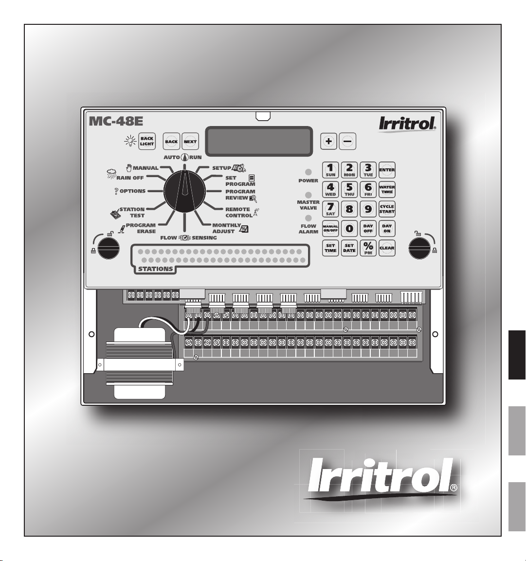
Thank you for purchasing the MC-E controller by Irritrol. The MC-E controller is a solid-state irrigation controller,
capable of storing eight independent programs designed to meet the needs of commercial and contractor applications. The
MC-E is an enhancement to the existing MC controller with many more functions and display features. The new MC-E is
designed to be compatible with the previous MC Plus B cabinets and wiring connections.
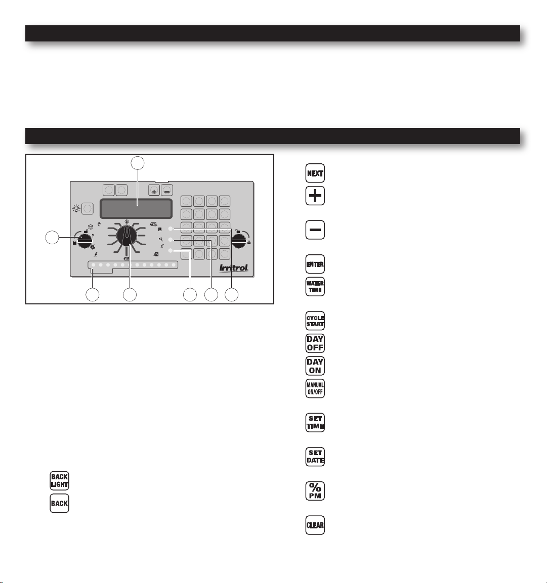
Parts Diagram
- Use to navigate through the menu options
- Use to navigate through the menu selections
or options
- Use to navigate through the menu selections
or options
- Finalize and save entered parameters
- SETUP - Assigns Station and Station
Runtime to a program
1 - 32-Character Dot Matrix LCD
2 - Timing Mechanism Quick Release
3 - Active Station Indicator Display
4 - Function Dial
5 - Flow Alarm Indicator LED
6 - Master Valve Active Indicator LED
7 - Power Supply Indicator LED
- Activates the LCD Display Backlight
- Use to navigate through the menu options
- SETUP - Assign Start Times to a program
- SETUP - Assign Event Days
- SETUP - Remove Event Days
- MANUAL - Activate stations or programs
manually
- SETUP / SET PROGRAM - Modify the
current time
- SETUP / SET PROGRAM - Modify current
date
- MONTHLY ADJUST - Adjust water budget
percentage.
- Clear / Delete selection / Revert back to the
main menu of the current dial position
3
Page 4
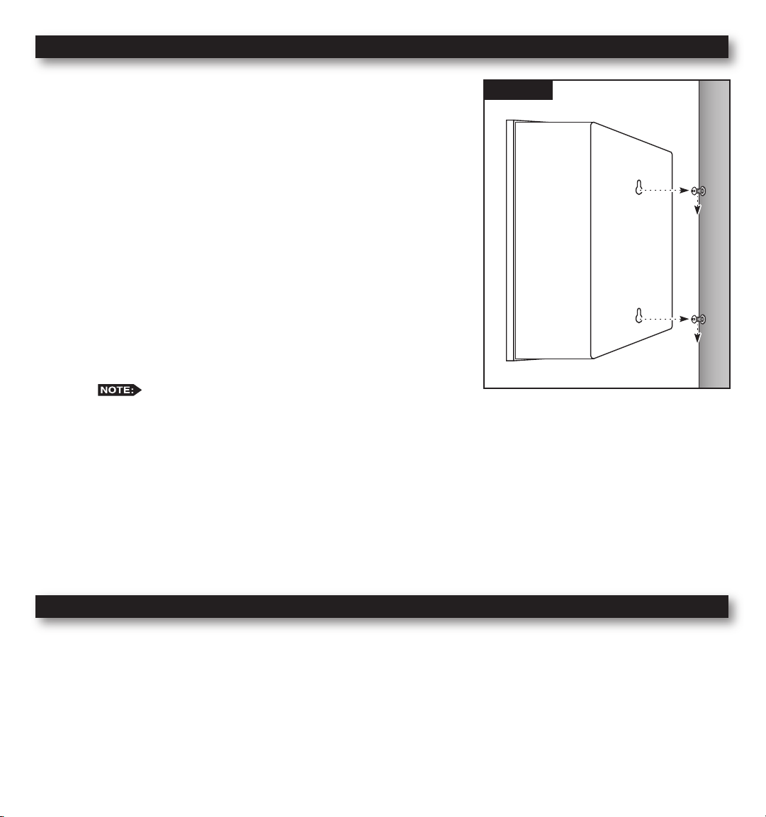
Cabinet Installation
Step 1 – Selecting the proper installation site for the MC-E controller is
essential to safe and reliable operation. The controller features
a weather resistant cabinet designed for indoor and outdoor
installation. The controller should be installed on a vertical wall
or other sturdy structure near a grounded power source. Select a
location that provides as much protection from direct sunlight,
rain, snow and irrigation spray as possible.
Step 2 – Drive a wood screw (provided) into the wall at eye level.
(For Large Cabinet Unit - 18 Stations or more) Drive another
wood screw 8” (20.3 cm) directly below the rst screw.
(For Small Cabinet Unit - 12 Stations or less) Drive another wood
screw 5 3/4” (14.5 cm) directly below the rst screw.
Leave approximately 1/4” (6.5 mm) of the screw extended from
the wall to accommodate the cabinet.
For drywall and masonry installation, use proper screw
anchors to prevent the screws from loosening.
Step 3 – Place the controller cabinet on the screws using the keyhole slots on the back panel. Ensure that the cabinet is
installed securely on the screws. See Figure 1.
Step 4 – Open the controller door and remove the bottom panel door. Locate the bottom screw and tighten it securely.
Figure 1
The MC-E series has two available lockable, weather and vandal resistant steel pedestals for free standing applications.
For MC-E controllers with 12 stations or less, use the Irritrol P-2B pedestal. For MC-E controllers with 18 stations or
more, use the Irritrol P-6B pedestal. Follow the installation and mounting instructions that are provided with the pedestal.
Electrical Conduit Installation
Electrical conduit and adapters are not supplied with the controller but may be required for installations in your area.
Check with your local electrical codes and install conduit according to requirements.
For power wires, install a 1/2” (13 mm) NPT threaded conduit access body to the transformer assembly threaded nipple.
From the access body, install conduit to the power source.
For station valve wiring, install a 2” (5 cm) conduit adapter and conduit.
4
Page 5
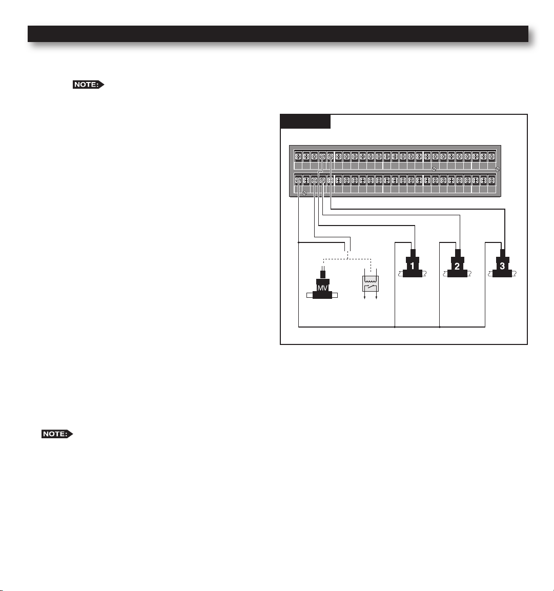
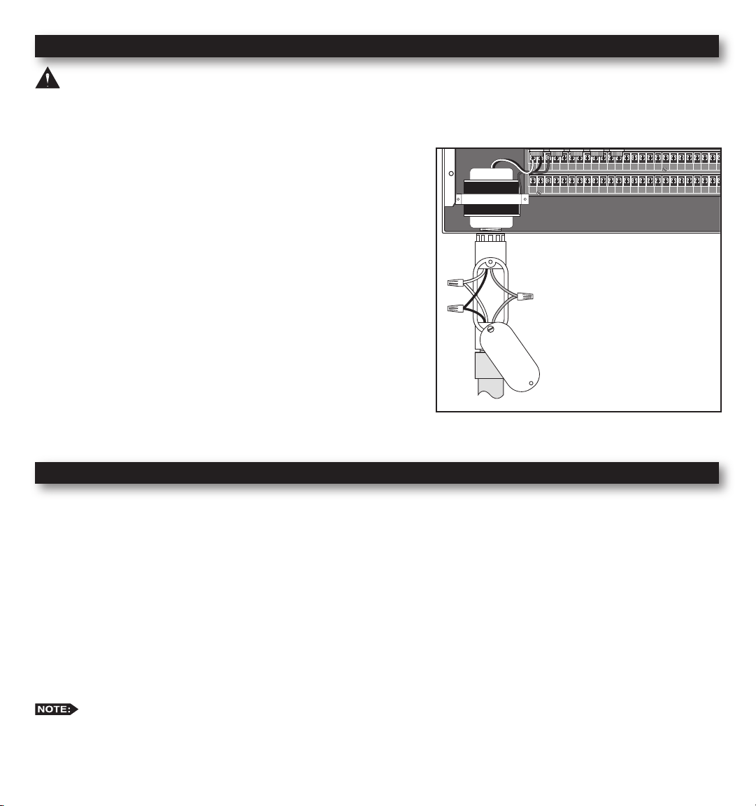
Control Wires Installation
VALVE
COMMON
VALVE
COMMON
VALVE
COMMON
MASTER
VALVE
YEL RED
VALVE
COMMON
GND
1 3 5 7 9 11 13 15 17 19 21 23 25 27 29 31 33 35 37 39 41
2 4 6 8 10 12 14 16 18 20 22 24 26 28 30 32 34 36 38 40 42
Step 1 – Route the valve control wires between the valves and the MC-E controller.
For wire runs up to 1000’ between the controller and the valves, it is recommended to use an 18 AWG
(1.0 mm2) multi-wire sprinkler valve connection cable. This cable is insulated for direct burial and is color
coded to simplify installation.
Step 2 – Attach one wire from each valve solenoid to
the white color-coded wire from the cable.
(Since the valve solenoid has no polarity, either
wire can be used for this connection.) Designate
this connection as the Valve Common.
Step 3 – Attach a separate cable wire to each of the
remaining valve solenoid wire. Take note of the
wire color being used for each valve as well
as the watering zone/area it is designated. This
information will be important when connecting
the valve wires to the controller’s station
terminals.
Step 4 – Use wire nut fasteners to secure the valve
solenoid wire connection. Waterproof all
connections with grease caps or similar
insulation method.
Figure 2
Wiring for standard (non-ow sensing) system
Master
*
Valve
Station 1
Pump Start
Relay
*Station 2
Station 3
Step 5 – Route the other end of the control wires into the
provided conduit hole at the bottom of the cabinet. Leave about 8” of cable remaining in the cabinet. Expose
about 3/8” of bare wire from the station and the valve common wires.
Step 6 – Secure the valve common wire to one of the three terminals labeled “VALVE COMMON” and each valve wire
* For ow monitoring, with a ow sensor installed, Station #2 is programmed and used as activation circuit for
to its appropriate station terminal designation.
a normally-open master valve instead of a regular station valve. (See page 36 “Install Critical Flow Shut Off
Master Valve”.)
5
Page 6

Rain Sensor Installation (Purchased Separately)
VALVE
COMMON
VALVE
COMMON
VALVE
COMMON
MASTER
VALVE
YEL RED
VALVE
COMMON
GND
1 3 5 7 9 11 13 15 17 19 21 23 25 27 29 31 33 35 37 39 41
2 4 6 8 10 12 14 16 18 20 22 24 26 28 30 32 34 36 38 40 42
1 3 5 7 9 11 13 15 17 19 21 23 25 27 29 31 33 35 37 39 41 43 45 47
2 4 6 8 10 12 14 16 18 20 22 24 26 28 30 32 34 36 38 40 42 44 46 48
INHIBIT SENSOR START SENSOR FLOW SENSOR
VALVE
COMMON
VALVE
COMMON
VALVE
COMMON
MASTER
VALVE
YEL RED
VALVE
COMMON
GND
1 3 5 7 9 11 13 15 17 19 21 23 25 27 29 31 33 35 37 39 41
2 4 6 8 10 12 14 16 18 20 22 24 26 28 30 32 34 36 38 40 42
1 3 5 7 9 11 13 15 17 19 21 23 25 27 29 31 33 35 37 39 41 43 45 47
2 4 6 8 10 12 14 16 18 20 22 24 26 28 30 32 34 36 38 40 42 44 46 48
INHIBIT SENSOR START SENSOR FLOW SENSOR
IMPORTANT! The INHIBIT SENSOR is designed for a
normally closed rain sensor. The wire jumper must be present at the
terminals if a sensor is not connected.
Step 1 – Route the rain sensor cable into the controller terminals.
Step 2 – Remove the wire jumper from the INHIBIT and SENSOR
terminals for the 18 stations or more models and
INHIB.SEN and SEN.COM for the 12 stations or less
models. Refer to the provided rain sensor installation
guide for wiring instructions and connect accordingly.
The INHIBIT SENSOR will operate on any
Function Dial position settings.
Start Sensor Installation (Purchased Separately)
IMPORTANT! The START SENSOR input is designed for
a normally open sensor and works in conjunction with Options 9
and 10. When the start sensor is activated, the MC-E controller will
immediately activate Program 1 providing Option 10 is activated.
Program 1 will continue to repeat the cycle until the start sensor is
deactivated. The activation of the start sensor will not affect any
other programs. Option 9 works similarly by turning ON program 8,
however all other programs are turned OFF.
Step 1 – Route the sensor connection cable through the bottom of
the controller cabinet and into the controller terminals.
Step 2 – Refer to the provided sensor installation guide for wiring
instructions.
The START SENSOR will operate on any
Function Dial position except for RAIN OFF.
6
SEN.COM START SEN.
Models with 12 Stations or Less
START SENSOR
Models with 18 Stations or More
Page 7
Power Source Installation
VALVE
COMMON
VALVE
COMMON
VALVE
COMMON
MASTER
VALVE
YEL RED
VALVE
COMMON
GND
1 3 5 7 9 11 13 15 17 19 21 23 25 27 29 31 33 35 37 39 41
2 4 6 8 10 12 14 16 18 20 22 24 26 28 30 32 34 36 38 40 42
1 3 5 7 9 11 13 15 17 19 21 23 25 27 29 31 33 35 37 39 41 43 45 47
2 4 6 8 10 12 14 16 18 20 22 24 26 28 30 32 34 36 38 40 42 44 46 48
WARNING: All electrical components and installation practices must meet applicable national and local electrical
codes including installation by a qualied personnel. These codes may require an external junction box mounted on the
cabinet and a circuit breaker in the main wiring having a contact separation of at least 0.120” in the line and neutral poles.
The 120 VAC power source must be turned OFF prior to servicing. The power cable used for connection to the controller
must have an insulation rating of 221° F minimum.
Step 1 – For power source connection, install a 1/2” electrical
conduit from the 120 VAC power source to the MC-E
controller cabinet.
Step 2 – Install an electrical junction box at the transformer to
allow access for future servicing.
Step 3 – Conrm that power has been disconnected at the power
source using a volt meter or voltage detector.
Step 4 – Route 14-AWG insulated solid copper wires for Power
(Black), Neutral (White) and Equipment Ground (Green)
through the conduit and into the junction box.
Step 5 – Strip back 3/8” of insulation from each wire. Using wire
connectors, connect the wires with similar colors together
(Black with Black, White with White, etc.).
Step 6 – Tuck the wires inside the junction box and replace the
cover.
Step 7 – Apply power to the controller.
Power Wire = Black
Neutral Wire = White
Equipment Ground = Green
Circuit Breaker Diagnostic System
The controller’s system for managing an electrical short circuit is designed to isolate the station with the problem and
continue to water operable stations. The sequence the controller follows is listed below.
1. The controller reaches a station with a short circuit.
2. The controller shuts off the problem station and skips to the next station in the same program and continues operation.
3. The controller displays “Fuse Alarm on __” and the problem station’s number as well as the other station in operation.
4. In between programs, when the controller is idle, it will display the Fuse Alarm station alternating with the display of
Day/Date/Time.
5. The next time the controller is supposed to run the station, it will try again. If the cause of the short has been repaired,
the Fuse Alarm will disappear from the display and the station will run normally. You can also use the CLEAR button
to clear the Fuse Alarm from the display. This does not x the shorted circuit, but only clears its display.
The controller has fractions of a second to detect and shutoff the problem station before the short circuit causes
damage. On occasion, with multiple programs and stations running, the controller shuts off and displays two stations as
having shorts. You can test each station in MANUAL mode or with STATION TEST to nd the shorted one.
7
Page 8
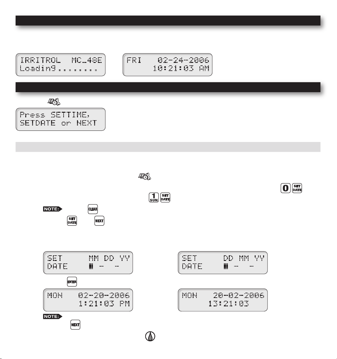
Power On / Reset Mode
MC-E will initiate the operating system and reload all saved data in the memory for stable operation every time the
controller is powered up. Place the Function Dial in the Auto/Run position for normal operation.
Initial Display Auto Run Mode Display
System SETUP
The SETUP function allows you to modify the following MC-E parameters:
• Current Date • Current Time
• Security Password • Event Days
• Enable/Disable Master Valve
SETUP – Current Date
Set Current Date
Step 1 – Place the Function dial to the SETUP position.
Step 2 – Set the date mode if necessary. To set the date to International format (Day/Month/Year), press .
To return to the default U.S. format, press .
Step 3 – Press the or the button to access the date setup screen.
Step 4 – Enter the Month, Date and Year in MM DD YY format. If the MC-E is operating in International format, enter
the Date rst, the Month second and the year last (DD MM YY).
Example: For February 20, 2006, press the 022006 buttons.
Step 5 – Press the button to accept the changes. The display will now reect the new date.
the NEXT button.
Step 6 – Return the Function dial to AUTO/RUN position to exit SETUP.
Press the
While in SET DATE mode, you can advance to the SET TIME mode by pressing
button to clear any “Key Entry Error”.
U.S. format
U.S. format
8
International format
International format
Page 9

SETUP – Current Time
Set Current Time
Step 1 – Place the Function Dial to the SETUP position.
Step 2 – Set the time mode if necessary. To set the time to International format (24-hour), press .
To return to the default U.S. format, press .
Step 3 – Press or press the button until the time setup screen is displayed.
Step 4 – Enter the Hour, Minutes and Seconds in H MM format. Enter the H MM for PM time.
International setting follows the 24-hour format.
Example: For 10:30am, enter 1030.
Step 5 – Press the button to accept the changes. The display will now reect the new time.
Step 6 – Return the Function dial to AUTO/RUN position to exit SETUP.
Press the
While in SET TIME mode, you can advance to the SET LANGUAGE screen by pressing the NEXT
button or go back to SET DATE by pressing the BACK button.
button to clear any “Key Entry Error”.
U.S. format
U.S. format
International format
International format
9
Page 10
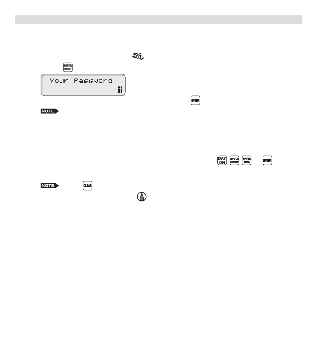
SETUP – Security Password
The MC-E can be secured with a security password to ensure that unauthorized users are not able to modify the programs.
Enable Security Password
Step 1 – Place the Function Dial to the SETUP position.
Step 2 – Press the button. The screen will display the following:
Step 3 – Enter a four-digit (0000–9999) security password and press the button.
security password before gaining access. However, manual operations are allowed.
Once the security password is veried, the MC-E will allow access to the menu functions for one hour. Within
that hour, you will be able to navigate through all the function dial positions without re-entering the security
password. After the 1-hour time limit expires, you will need to re-enter the password to gain access to the
menu functions.
In the event that you have forgotten the four-digit security password, press , , and to disable
the password verication process. To reestablish password security to the controller, you must repeat Steps
1–3.
Step 4 – Return the Function dial to AUTO/RUN position to exit SETUP.
Once a security password is established, all menu functions will require you to enter the four-digit
Press the
button to clear any “Key Entry Error”.
10
Page 11
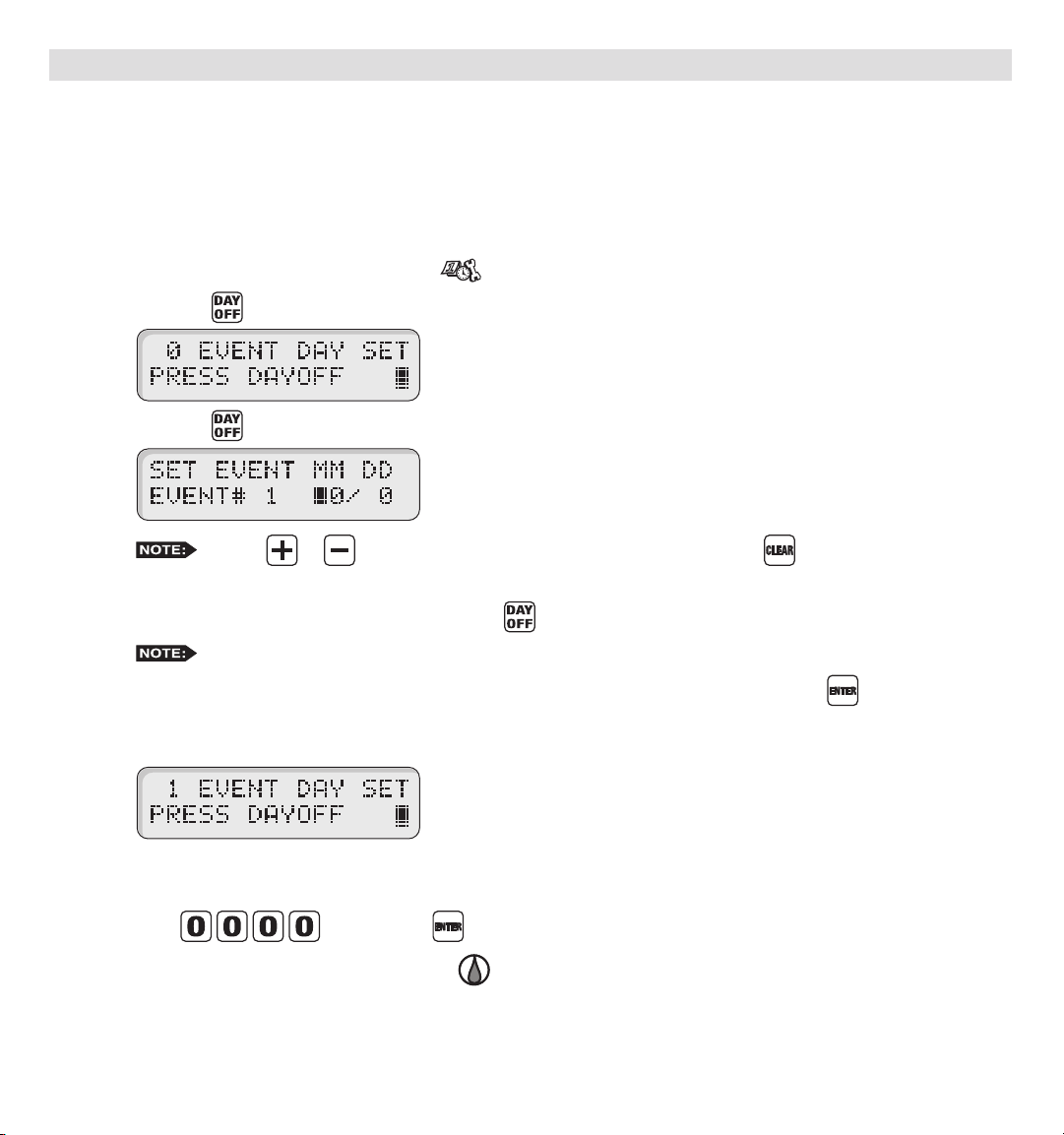
SETUP – Event Days
The MC-E allows you to pre-program ten event days throughout the year. During an event day, the controller will suspend
automatic watering. Event days will reoccur every year unless deleted.
Example: If July 4th is set as an event day, the controller will ignore watering every July 4th of each year until it is
deleted from the Event Days.
Set Event Day:
Step 1 – Place the Function Dial to the SETUP position.
Step 2 – Press the button. The screen will display the following:
Press the button to review the day off events or enter new events. The screen will display the following:
Entry Error”.
Step 3 – Enter the Event number (1–10), then press the button.
Step 4 – Enter the Month and Date (MM DD) of the event day being programmed and press the button. When
the controller is in International mode, enter the Date rst before the Month (DD MM). The controller will
increment the total event day and display the following:
Step 5 – Repeat Steps 2–3 for additional event days.
Step 6 – To delete an event, scroll through the event number to select it. Once the event is displayed,
enter
Step 7 – Return the Function dial to AUTO/RUN position to exit SETUP.
Use the or button to review the programmed events.
MC-E will re-number the event day if the newly created event is deleted.
and press the button to delete.
11
Press the
button to clear any “Key
Page 12
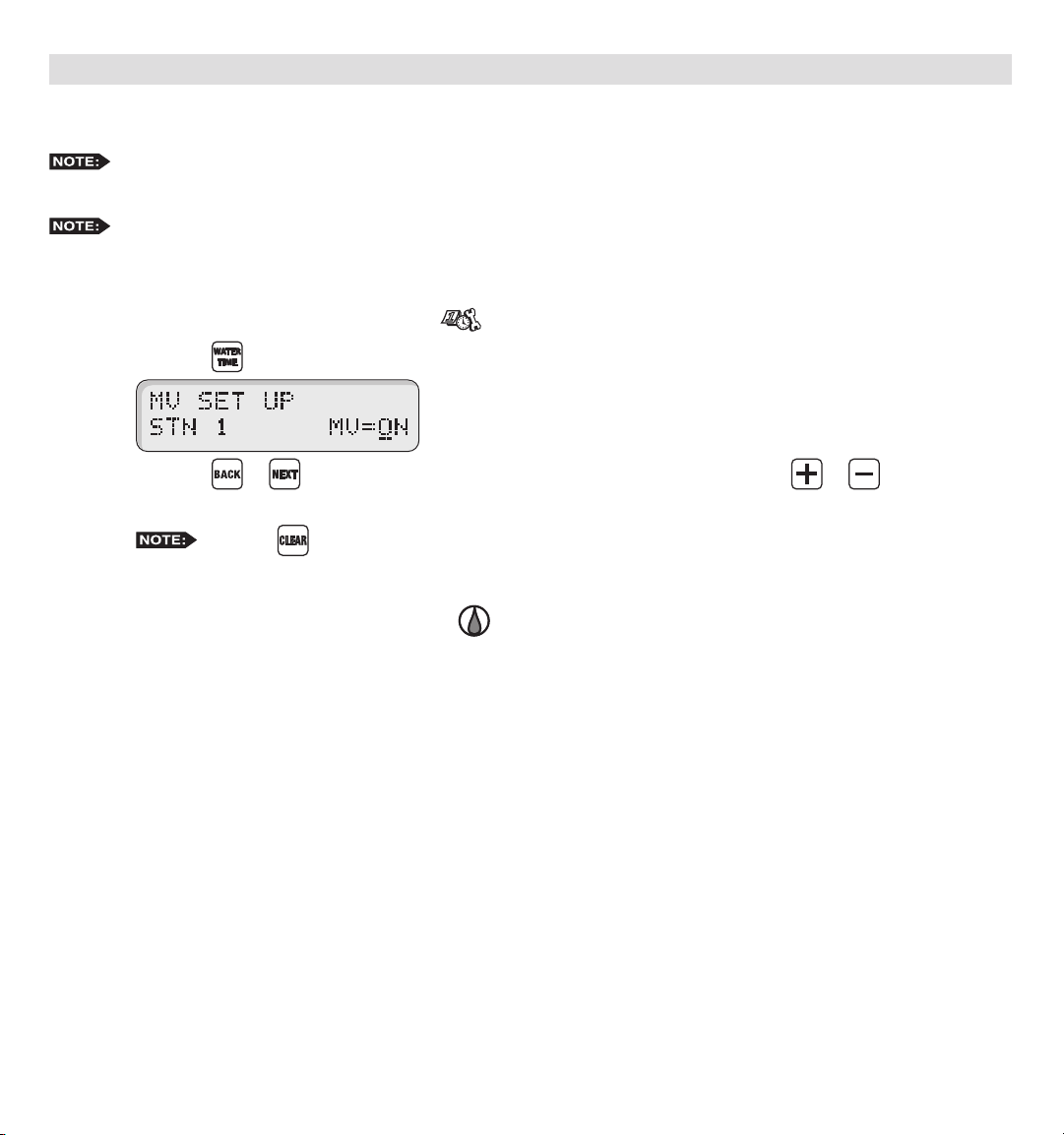
SETUP – Master Valve
Set Master Valve
As factory default, the Master valve is Enabled for all stations. The master valve will activate whenever a station
is activated.
If ow sensing is to be activated, all stations must be set to “MV=ON”.
In situations that a station does not require the master valve to activate, use the following procedure to select the station
and Disable or Enable the master valve.
Step 1 – Place the Function Dial to the SETUP position.
Step 2 – Press the button. The following display will be shown on the screen.
Step 3 – Press the or buttons to select the station number you want to edit. Use the or button to
toggle MV (Master Valve) from ON or OFF.
Step 4 – Repeat Step 3 for additional stations.
Step 5 – Return the Function dial to AUTO/RUN position to exit SETUP.
Press the
button to clear any “Key Entry Error”.
12
Page 13

Program SETUP
For a watering program to operate properly, it must have a station(s) with a runtime and a specic date and time to
activate. The following program parameters can be dened and/or modied in the SET PROGRAM function:
• Assign Station and Runtime to a Program • Assign Watering Day Schedule
• Assign Station Delay Time - Exclusion Day
• Assign Program Start Time - Odd Day
• Assign Looping Start Time - Even Day
• Assign Water Budget - Interval Day
Set Program – Assign Station and Runtime to a Program
Assign Station and Runtime to a Program
Step 1 – Place the Function Dial to the SET PROGRAM position.
Step 2 – Enter the program number (1–8) you want to create or modify. Press to activate your selection.
Step 3 – Enter the station number being added or modied in the program and press the button.
Press the
Step 4 – Enter the station runtime in MM (Minutes), H MM (Hours:Minutes) or 0:SS (0:Seconds [10 seconds
minimum]) and press . To enter a station runtime in seconds, enter “0” rst before entering the number of
seconds. For example, to enter 30 seconds of runtime you must press .
Repeat Steps 3–4 for additional stations and runtimes.
To assign similar runtimes to a group of stations, go to Step 2. After entering the program number (1–8) and
pressing , press and press . Then enter the two-digit station number of the lowest station and
the two-digit station number of the highest station in the group (i.e. 0912 will designate stations 9 through 12
in the group) and press again. Enter the length of runtime, then press . This procedure will replace all
station runtimes in the group with the new runtime.
Step 5 – Return the Function dial to AUTO/RUN position to exit SET PROGRAM.
Entering a station number that exceeds the controller’s station count will return an error message.
button to clear any “Key Entry Error”.
Enter a runtime value of 0 minutes to delete.
13
Page 14

Enter/Modify/Delete - Single or Multiple Stations
Step 1 – Place the Function Dial to the SET PROGRAM position.
Step 2 – Enter the program number (1–8) being modied. Press to activate the selection.
Step 3 – Enter the station number you want to create, modify or delete from the program and press the button.
Select multiple stations by entering the rst station number (two digits), then enter the last station in the
sequence (two digits) and press the button.
Step 4 – Assign the station runtime and press the button. If the station has a previous runtime, the newly entered
runtime will overwrite the previous value. Enter a runtime value of 0 minutes to delete.
Step 5 – Repeat Steps 3–4 to enter/modify/delete additional station(s) from the program.
Step 6 – Return the Function dial to AUTO/RUN position to exit SET PROGRAM.
Press the
Entering a station number that is not assigned to the program will return a “No Runtime” message.
button to clear any “Key Entry Error”.
Review Program Runtimes
Step 1 – Place the Function Dial to the SET PROGRAM position.
Step 2 – Enter the program number (1–8) being modied. Press to activate the selection.
Step 3 – Press the button once to review the program’s cumulative runtime.
Press the
button to clear any “Key Entry Error”.
Press the button twice to review individual station’s runtime in the program. The controller will
sequentially scroll through the program’s active stations along with their corresponding runtime.
Step 4 – Return the Function dial to AUTO/RUN position.
14
Page 15

Set Program – Program Start Time
Set Program Start Times
Each MC-E program can have up to eight start times. Programs can start at anytime except midnight.
Step 1 – Place the Function Dial to the SET PROGRAM position.
Step 2 – Enter the program number (1–8) being modied. Press to activate the selection.
Press the button to review all start times. Each programmed start times will be displayed
momentarily until the last start time is shown.
Step 3 – Enter the start time number (1–8) being created/modied and press the button. Enter the start time in
H MM (Hours and Minutes) and press .
The start time number will adjust according to the start time sequence. If assigning start time 4 with 6:00am
and currently, the earliest start time is at 7:30am, 6:00am will automatically become start time number 1 and
adjust the start time numbers according to the overall runtime for that program.
Example: Assign 5:30am to start time number 1 for program 1 by entering 0530 .
the station runtimes and station delays to the start time.
If the assigned start time will result with an end time past midnight, the controller will emit a long beep to
indicate that end time will run to the next watering day schedule. An asterisk (*) next to the end time also
indicate that the displayed end time is effective past midnight.
Enter H MM for PM time. (U.S. Time Mode)
The 05:55am time indicated on the display is the end time. This is calculated by adding the sum of all
Press the
button to clear any “Key Entry Error”.
Step 4 – Return the Function dial to AUTO/RUN position to exit SET PROGRAM.
beeps and see an asterisk in the display to alert you of the situation. The controller will complete the cycle
that initiates before midnight and completes it even after midnight. However, any subsequent start times in the
same program that were pushed into the next day will be lost. Check your start times and adjust accordingly.
Do not use midnight as a start time.
If setting a start time causes as overlap through midnight (day changeover), you will hear two long
15
Page 16

Delete Program Start Time
Step 1 – Place the Function Dial to the SET PROGRAM position.
Step 2 – Enter the program number (1–8) being modied. Press the to activate the selection.
Step 3 – Press the button to review all start times. Each programmed start times will be displayed momentarily
until the last start time is shown.
Step 4 – Enter the start time number (1–8) being deleted and press the button. Assign a start time of 0 and
press to nalize.
i.e., After deleting start time 1, start time 2 will ll in start time 1 slot and so on.
Step 5 – Return the Function dial to AUTO/RUN position to exit SET PROGRAM.
Step 6 – Repeat Steps 1–5 to delete additional start times.
Press the
After deleting a Start, MC-E will renumber remaining the start times to ll the empty start time slot.
button to clear any “Key Entry Error”.
16
Page 17

Set Program – Station Delay Time
Station delay time is the adjustable delay period between station operations. The controller’s default station delay is 0
seconds. The maximum delay time you can set between station operation is 4 hours.
Assign Station Delay Time
Step 1 – Place the Function Dial to the SET PROGRAM position.
Step 2 – Enter the program number (1–8) being modied. Press the to activate the selection.
Step 3 – Press the and buttons to access the station delay function.
Step 4 – Enter the station delay duration in H MM SS (Hours, Minutes and Seconds) and press .
Example: To assign a 30-second station delay to program 1, enter 0 00 30.
Step 5 – Return the Function dial to AUTO/RUN position to exit SET PROGRAM.
Press the
To disable the station delay, assign 0 for the time duration.
button to clear any “Key Entry Error”.
17
Page 18

Set Program – Looping Start Time
The MC-E has the capability to loop a program. When a program is set to loop, the program will repeat after the loop
delay time is satised. The program will continue to repeat beginning from the start time until the designated end time.
To initiate the program to loop, you must assign a start time, end time and a loop delay to the program.
Set a Looping Start Time
Step 1 – Establish a start time to the program. (See Set Program – Program Start Time section.)
Step 2 – Assign a program End time. Place the Function Dial to the SET PROGRAM position. Enter the program
number being modied. Enter
Enter the program end time in H MM format and press . Use the button for PM.
Example: Enter 6:00am start time and 10:00pm end time.
Press the
button to clear any “Key Entry Error”.
to access the loop function.
Step 3 – You must assign a loop delay by entering
One minute loop delay is the minimum.
Example: Assign a 30-minute loop delay. Enter
Step 4 – Return the Function dial to AUTO/RUN position to exit SET PROGRAM.
IMPORTANT! A looping program must have it’s start time and end time programmed to occur on the
same day. Looping through midnight (end time is on another day) may cause the end time to be ignored or lost.
After establishing a loop, any additional program start time(s) will be deleted.
. Enter the delay time in H MM or MM and press .
18
.
Page 19

Modify a Looping Start Time
Step 1 – Place the Function Dial to the SET PROGRAM position.
Step 2 – Enter the program number (1–8) being modied. Press the to activate the selection.
Step 3 – Press to enter a new loop start time in H MM format (Hours, Minutes and for PM)
and press to accept.
Step 4 – Press
and press to accept.
Step 5 – Press
Step 6 – Return the Function dial to AUTO/RUN position to exit SET PROGRAM.
Press the
button to clear any “Key Entry Error”.
to enter a new loop end time in H MM format (Hours, Minutes and for PM)
to enter a new loop delay time in H MM format (Hours, Minutes) and press to accept.
Delete a Looping Start Time
Step 1 – Place the Function Dial to the SET PROGRAM position.
Step 2 – Enter the program number (1–8) being modied. Press the to activate the selection.
Step 3 – Enter and press to clear the looping start time. (The start time and end time are
automatically deleted.)
Press the
button to clear any “Key Entry Error”.
Step 4 – You must re-enter a start time to reactivate the program. (See Set Program – Program Start Time section.)
Step 5 – Return the Function dial to AUTO/RUN position to exit SET PROGRAM.
19
Page 20
Set Program – Watering Day Schedule
The MC-E offers you several options to schedule your watering programs. Having multiple options will allow you to
optimize your watering need while practicing water conservation.
Each of the eight controller programs can be set to one of the following schedule options:
• Days of the Week / Exclusion Days
• Odd Days Watering w/ Exclusion Days
• Even Days Watering w/ Exclusion Days
• Skip Days
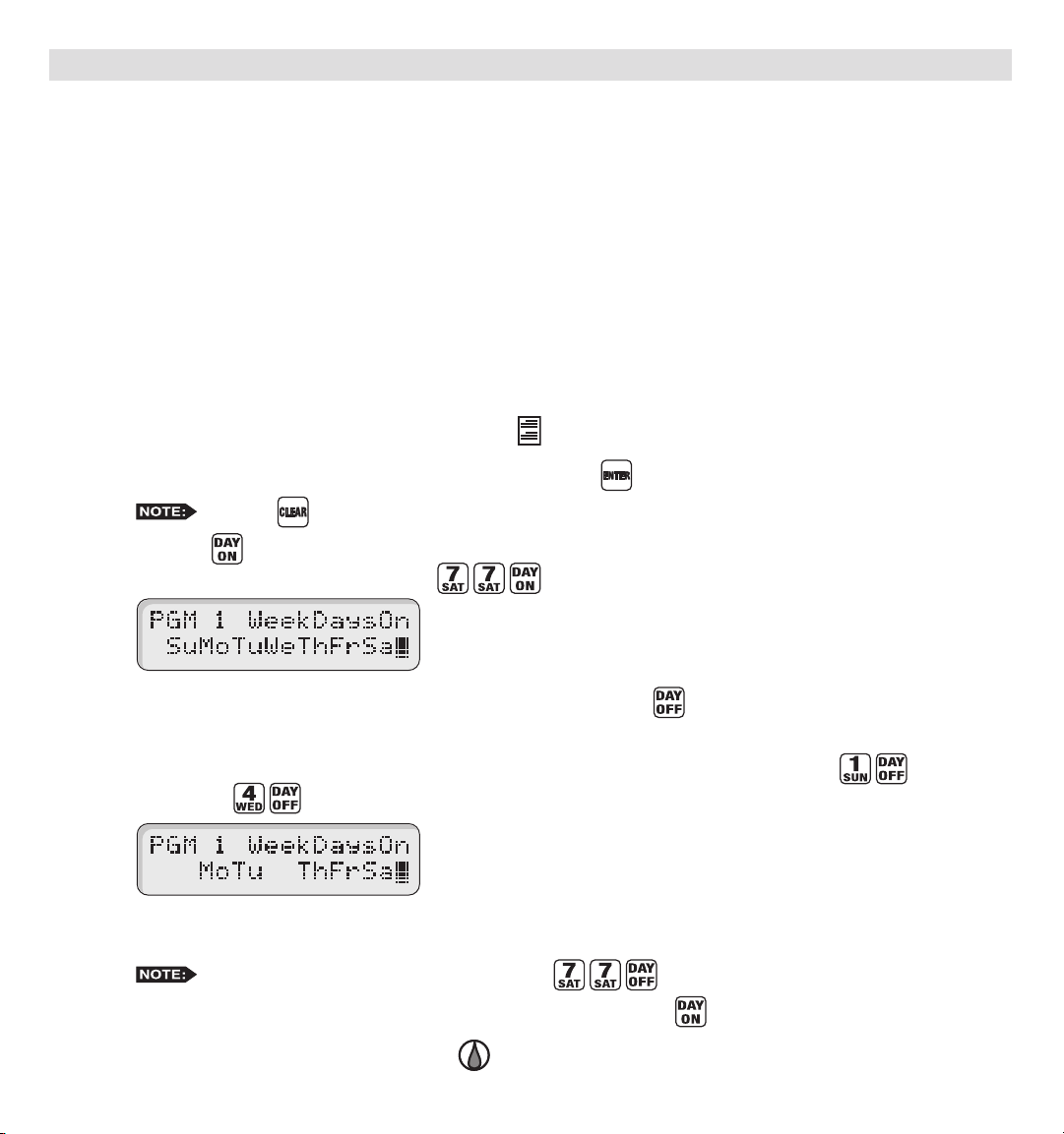
Set Program Schedule to Days of the Week / Exclusion Days
Step 1 – Place the Function Dial to the SET PROGRAM position.
Step 2 – Enter the program number (1–8) being modied. Press the to activate the selection.
Step 3 – Press the button to review the program schedule. The Weekdays scheduling is the factory default. If Odd
or Even scheduling is activated, press to reestablish Weekdays scheduling.
Step 4 – To exclude a day, enter the day designation number and press the button.
Su = 1, Mo = 2, Tu = 3, We = 4, Th = 5, Fr = 6 and Sa = 7
Example: Deactivate Sunday (Su) and Wednesday (We) to the Weekdays schedule. Press to deactivate
Sunday and buttons to deactivate Wednesday.
The remaining days, Monday, Tuesday, Thursday, Friday and Saturday are all active days. The program will
run only on these days.
Step 5 – To re-activate a day, enter the day designation number and press the button.
Step 6 – Return the Function dial to AUTO/RUN position to exit SET PROGRAM.
Press the
To deactivate all the days of the week, press .
button to clear any “Key Entry Error”.
20
Page 21

Odd Days watering schedule will activate the program on the odd-numbered days in the calendar month (1, 3, 5, ..., 29).
Set Program Schedule to Odd Days
Step 1 – Place the Function Dial to the SET PROGRAM position.
Step 2 – Enter the program number (1–8) being modied. Press the to activate the selection.
Step 3 – Press the button to activate Odd days watering schedule.
Step 4 – Return the Function dial to AUTO/RUN position to exit SET PROGRAM.
In conjunction to setting your irrigation schedule to Odd Days of the calendar schedule, you can also deactivate any day
of the week.
Press the
button to clear any “Key Entry Error”.
Set Program Schedule to Odd Days with Excluded Days
Step 1 – Set watering schedule to Odd days. (See section “Set Program Schedule to Odd Days”.)
Step 2 – To exclude a day, enter the day designation number and press the button.
Su = 1, Mo = 2, Tu = 3, We = 4, Th = 5, Fr = 6 and Sa = 7
Example: Deactivate Wednesday (We) and Saturday (Sa) to the Weekdays schedule. Press to
deactivate Wednesday and buttons to deactivate Saturday.
Step 4 – Return the Function dial to AUTO/RUN position to exit SET PROGRAM.
To return the program’s scheduling to Weekdays, press the buttons.
21
Page 22

Even Days watering schedule will activate the program on the Even-numbered days in the calendar month (2, 4, 6, ..., 30).
Set Program Schedule to Even Days
Step 1 – Place the Function Dial to the SET PROGRAM position.
Step 2 – Enter the program number (1–8) being modied. Press the to activate the selection.
Step 3 – Press the button to activate Even days watering schedule.
Step 4 – Return the Function dial to AUTO/RUN position to exit SET PROGRAM.
In conjunction to setting your irrigation schedule to Even Days of the calendar schedule, you can also deactivate any day
of the week.
Press the
button to clear any “Key Entry Error”.
Set Program Schedule to Even Days with Excluded Days
Step 1 – Set watering schedule to Even days. (See section “Set Program Schedule to Even Days”.)
Step 2 – To exclude a day, enter the day designation number and press the button.
Su = 1, Mo = 2, Tu = 3, We = 4, Th = 5, Fr = 6 and Sa = 7
Example: Deactivate Sundays (Su) and Fridays (Fr) to the Weekdays schedule. Press to deactivate
Sundays and buttons to deactivate Fridays.
Step 4 – Return the Function dial to AUTO/RUN position to exit SET PROGRAM.
To return the program’s scheduling to Weekdays, press the buttons.
22
Page 23

Skip Days watering schedule will activate the program within the specied interval. You can designate skip days from
1 through 59 days between watering days. The entered value will be the number of days the controller will skip until an
active watering day. If you enter a value of 3, MC-E skip watering for 3 consecutive days and water on the fourth day.
MC-E will repeat the schedule after the active day.
Set Skip Days Program Schedule
Step 1 – Place the Function Dial to the SET PROGRAM position.
Step 2 – Enter the program number (1–8) being modied. Press the to activate the selection.
Step 3 – Press the button to activate Skip days watering schedule. Default settings are “0” days and “0” skips.
Step 4 – Enter the designated Skip day number and press the button. (1 = skip 1 day then water the next day,
2 = skip 2 days then water the next day, etc.)
Example: Set the program to skip 4 days before activating. Press .
Step 5 – Enter today’s designation number and press the button. This number represents the current day’s position
within the schedule interval. This number will increment on a daily basis starting from 0 (zero) until the
skip day number designation is met. When the skip day number and the “Today” number are equal, then the
controller will regard that day as the program’s watering day.
Example: With skip day set to 4, the program is set to skip days 0, 1, 2 and 3. Set today so that the controller
will water the next day. Enter and press the button.
Press the
button to clear any “Key Entry Error”.
Step 6 – Return the Function dial to AUTO/RUN position to exit SET PROGRAM.
To return the program’s scheduling to Weekdays, press the buttons.
23
Page 24

Monthly Adjust / Water Budget
The MC-E water budget feature maximizes water conservation by allowing you to micro-adjust watering on a
monthly basis. By adjusting your irrigation during dry seasons, wet seasons, etc., you can be sure that your landscape
areas are receiving the optimum irrigation while conserving water resource.
Adjust the Monthly Water Budget
Step 1 – Place the Function Dial to the MONTHLY ADJUST position.
ADJUST position. Each monthly percent budget will display momentarily.
Step 2 – Use the or buttons to scroll and select the month being adjusted. You can also enter the Month’s
designation number and press the button to select a specic month.
Example: Select December to adjust. Press .
Step 3 – Use the or buttons to adjust the watering percentage. The or buttons will
increment/decrement the percentage by 10%. Press to save any changes.
In addition, you can adjust the percentage by entering the percentage number using the key pad and pressing
the button to accept.
Example: Adjust December’s watering to 85%. Press .
To review all monthly adjustments, simply press the button twice while in the MONTHLY
Press the
You can adjust the monthly watering budget down to 0% (OFF) and up to 200%.
button to clear any “Key Entry Error”.
Step 4 – Repeat Steps 2 and 3 to adjust additional monthly water budget.
Step 5 – Return the Function dial to AUTO/RUN position to exit MONTHLY ADJUST.
CAUTION: Increasing either the program water budget or the monthly water budget percentage may shift station
operations to past midnight. During start time review, an asterisk will be displayed alerting you to the situation. The
controller will complete programs that start before midnight and end after midnight. However, program start times that
have been shifted past midnight (after day change) may be lost. Check your start times and adjust accordingly.
24
Page 25

Set Water Budget per Program
Step 1 – Place the Function Dial to the SET PROGRAM position.
Step 2 – Enter the program number (1–8) being modied. Press the to activate the selection.
Step 3 – Press the button.
Step 4 – Enter the desired water budget percentage for the selected program. You can decrease the program’s watering
to 0% (no watering) or increase it up to 200%. Press the button to accept the water budget modication.
Example: Increase Program 1’s watering budget to 150%. Press the button and enter to set
budget at 150%. Press to accept.
Step 5 – Repeat steps 2–4 to modify additional program water budgets.
increase or decrease of the watering cycle.
Example: Station 1 of Program 1 has a normal runtime of 5 minutes. If the program water budget is set at
200% then the adjusted run time will be 10 minutes (5 min X 2 = 10 min). If the Monthly Adjustment is also
set at 200% for the current month, then the adjusted run time will be 20 minutes (5 min X 2 X 2 = 20 min).
Press the
The Monthly percent adjustment and the water budget percentage will multiply together to get the net
button to clear any “Key Entry Error”.
Step 6 – Return the Function dial to AUTO/RUN position to exit SET PROGRAM.
CAUTION: Increasing either the program water budget or the monthly water budget percentage may shift station
operations to past midnight. During start time review, an asterisk will be displayed alerting you to the situation. The
controller will complete programs that start before midnight and end after midnight. However, program start times that
have been shifted past midnight (after day change) may be lost. Check your start times and adjust accordingly.
25
Page 26

Program Review
Use this function to review program parameters. Parameter modication is not allowed while in review mode.
Review the Program’s Parameters
Step 1 – Place the Function Dial to the Program Review position.
Step 2 – Enter the program number being reviewed.
Step 3 – Press the following buttons in the order below to review the parameters:
Step 4 – Return the Function dial to AUTO/RUN position to exit Program Review.
Press the
- Review the stations and the corresponding runtimes that are assigned to the selected program. When
pressed twice, MC-E will sequentially display all activated stations and their runtimes. To review
individual stations, enter the station number and press the button.
- Review all assigned start times in the program. When pressed, the MC-E will sequentially display all
start times beginning from the earliest. Review a specic start time by entering the start time number and
pressing the button.
- Review the program schedule.
- Review the program’s water budget.
button to clear any “Key Entry Error”.
26
Page 27

Program Erase
Program Erase – Single Program
Erase Single Program
Step 1 – Place the Function Dial to the Program Erase position.
Step 2 – Enter the program number being erased and press to process.
Example: Erase program 8 by pressing the buttons.
Step 3 – After the deletion, the display will show the following.
Repeat Step 2 to delete additional programs.
assigned but it will have all Days of the Week (Sunday through Saturday) active.
Step 4 – Return the Function dial to AUTO/RUN position to exit Program Erase.
Press the
Erasing a program will revert it back to default. Program default will have no station and runtime
button to clear any “Key Entry Error”.
27
Page 28

Program Erase – Complete Program Reset
Activating this function will erase all saved irrigation programs in the MC-E controller. However, it will not erase the
current time, date or any Option or SETUP settings.
Reset All Programs
Step 1 – Place the Function Dial to the Program Erase position.
Step 2 – Enter and press .
Press the button to exit or press to accept.
Step 3 – Return the Function dial to AUTO/RUN position to exit Program Erase.
Press the
button to clear any “Key Entry Error”.
Program Erase – Complete Controller Reset
Activating this function will erase all data settings in the MC-E controller. The rmware will revert back to factory default
settings.
Reset the Controller
Step 1 – Place the Function Dial to the Program Erase position.
Step 2 – Enter and press .
Press the button to exit or press to accept.
Press the
button to clear any “Key Entry Error”.
Step 3 – Return the Function dial to AUTO/RUN position to exit Program Erase.
28
Page 29

Station Test
The MC-E provides the Station Test to allow you to activate all stations whether they are assigned to a program or not.
When a Station Test is performed, the controller will sequence through all the stations and activate them for the specied
duration.
Perform Station Test
Step 1 – Place the Function Dial to the Station Test position.
Step 2 – Enter the station runtime from 01 second to 30 minutes (seconds must be entered with 0 rst, i.e. 45 seconds,
enter 045) and press the to initiate the test.
for two minutes.
Example: Test each station by activating them for one minute. Press the buttons.
Press the button to advance to the next station if the test time per station is in minutes.
Press and button to advance to the next station if the selected test time per station
is in seconds.
Place the Function Dial to (RAIN OFF) position to Cancel the procedure.
Step 3 – Return the Function dial to AUTO/RUN position to exit Station Test.
If no runtime is entered before pressing the button, the controller will test each station
Press the
button to clear any “Key Entry Error”.
29
Page 30

Options 1–8
To set station 1 as a normally-closed master valve and assign it to any program, Program 1 (Option 1) through
Program 8 (Option 8).
Activate Option 1–8 to Activate Secondary Master Valve (Station 1)
Step 1 – Place the Function Dial to the Options position.
Step 2 – Use the and buttons to select the program to modify. Use the and buttons to set the Master
Valve to Master or Station 1.
Example: Set Program 2 to use Station 1 as a secondary master valve. Press the or button until
Option# 2 is displayed. Press the or button to toggle the Master Valve option to STN 1.
Step 3 – Repeat Step 2 to modify additional programs.
Step 4 – Return the Function dial to AUTO/RUN position to exit Options.
Options 9 (Activate Exclusive Program with Start Sensor)
Option 9 is used in conjunction with the Start Sensor and Program 8. With Option 9 set to “PGM 8 Start=ON” and
the Start Sensor is activated, all automatic and manual watering will turn off and program 8 will immediately turn on.
Automatic programs will be suspended until the Start Sensor is deactivated. As long as the Start Sensor is activated,
Program 8 will continue to repeat its cycle.
Activate Option 9
Step 1 – Place the Function Dial to the Options position. Press the or button until Option 9 is displayed.
Step 2 – Use the or button to activate or deactivate Option 9. When activated, program 8 will start when the
start sensor is triggered.
Step 3 – Return the Function dial to AUTO/RUN position to exit Options.
If program 8 has no value, the controller will function normally.
30
Page 31

Options 10
Option 10 is used in conjunction with the Start Sensor and Program 1. With Option 10 set to “PGM 1 Start=ON” and the
Start Sensor is activated, Program 1 will turn on immediately. Program 1 will repeat the cycle continuously until the start
sensor is deactivated. All other programs will not be affected and will activate as scheduled.
Application Example: Activate dust control program with wind sensor, allow other programs to continue.
Activate Option 10
Step 1 – Place the Function Dial to the Options position. Press the or button until Option 10 is displayed.
Step 2 – Use the or button to activate or deactivate Option 10. When activated, program 1 will start when the
start sensor is triggered.
Step 3 – Return the Function dial to AUTO/RUN position to exit Options.
If program 1 has no value, the controller will function normally.
If Option 9 is activated, it will take precedence over Option 10. (See “Option 9” on page 30.)
Options 11
Option 11 is used to activate or deactivate the master valve during station delays.
Application Example: Water well recovery between station operations where the well needs to rell from ground water.
The MV/Pump circuit would be OFF during the delay period.
Activate Option 11
Step 1 – Place the Function Dial to the Options position. Press the or button until Option 11 is displayed.
Step 2 – Use the or button to toggle Master Valve function from ON or OFF during station delays.
Step 3 – Return the Function dial to AUTO/RUN position to exit Options.
31
Page 32

Rain Off
The MC-E provides Rain Off to temporarily suspend the controller’s automatic watering. When Rain Off is activated,
automatic watering cycles are halted until the Rain Off duration has elapsed. Rain Off can be programmed from 0 (Rain
Off deactivated) to 14 days.
Activate Rain Off
Step 1 – Place the Function Dial to the Rain Off position.
Step 2 – The MC-E will execute a 3-second countdown to cancel any active watering. In this function dial position, all
automatic watering will halt until it is returned to Auto Run position.
Step 3 – You can also set a specic rain delay duration in days.
Example: Place the controller in Rain Off for three days. Enter the desired
days off, in this case , and press the button to accept.
until day 0 is met. At day 0, all automatic watering is restored. Disable the Rain Off feature by entering a Rain
Off value of 0 day.
Step 3 – Return the Function dial to the AUTO/RUN position to exit Rain Off.
will not shut it off.
3 Days indicate that the current day is day number 3. The controller will countdown at day change
Press the
If station #2 is set as the normally-open master and activated (for ow sensing feature) RAIN OFF
button to clear any “Key Entry Error”.
Semi-Auto Operation
The Semi-Auto operation allows you to manually activate up to six programs regardless of run times. Before starting
multiple, overlapping programs, make sure your system can support the increased hydraulic demand.
Activate Semi-Auto
Step 1 – Place the Function Dial to the SET PROGRAM position.
Step 2- Enter the program number you want to activate. Press to accept. Press either the button for the number
of the rst station in the program or the number of the station within the program where you wish to start the
semi-automatic run. Then press . (If you do not remember the rst station in the program, pressing “1” will
automatically select the program’s rst station for the semi-auto start.)
Example: With the Function Dial at SET PROGRAM , press and . If station 8 is where you want
Program 2’s semiautomatic run to start, press and to start the operation. If you do not know which
stations are in Program 2, just press and . Program 2’s rst station will start.
Step 3 – Return the Function Dial to AUTO/RUN position. The controller will nish the semi-auto run of the
remaining stations for the selected program and then await its next automatic start time.
32
Page 33

Step 4 – Repeat steps 1 through 3 to start other programs semi-automatically. The controller will allow the semi-
automatic programs to overlap or run concurrently.
Step 5 - To turn off selected programs’ semi-automatic runs, turn the dial to SET PROGRAM , enter the Program’s
number and then press . This will turn off only the selected program. Other semiautomatic runs are
unaffected. Return the dial to AUTO/RUN .
leave the controller in automatic mode.
To turn off all ongoing operations, turn the dial to RAIN OFF. Return the dial to AUTO/RUN to
Manual Operation
The MC-E provides True Manual operation feature for unscheduled station activation. With True Manual, the selected
station will then water until you turn it off or until the controller’s current time reaches midnight. As a safety precaution,
the controller is programmed to halt Manual watering at midnight. When Manual is in operation, MC-E will beep every
30 seconds to indicate active operation.
Activate Station Manually
Step 1 – Place the Function Dial to the Manual position.
Step 2 – Enter the station number you want to activate. Press the button to activate.
Example: Activate Station 5. Enter and press the button.
IMPORTANT! The MC-E “True Manual” feature requires you to turn the operation off once activated.
Otherwise, the manual operation is designed to activate until midnight. Notice that the displayed manual
operation runtime will always end at midnight.
Only one station can be manually activated, multiple station activation is not allowed.
You can move the station number back or forward by pressing the or button.
Step 3 –
Return the Function dial to AUTO/RUN position to deactivate manual operation and place the controller
back to Auto Run mode.
Manual watering has the least priority. If a scheduled program activated the maximum available
active stations, then Manual operation will not run. When the maximum allowed active stations is reached
while manual operation and scheduled program are running, the Manually activated stations will deactivate to
accommodate the stations in the automatic program.
33
Page 34
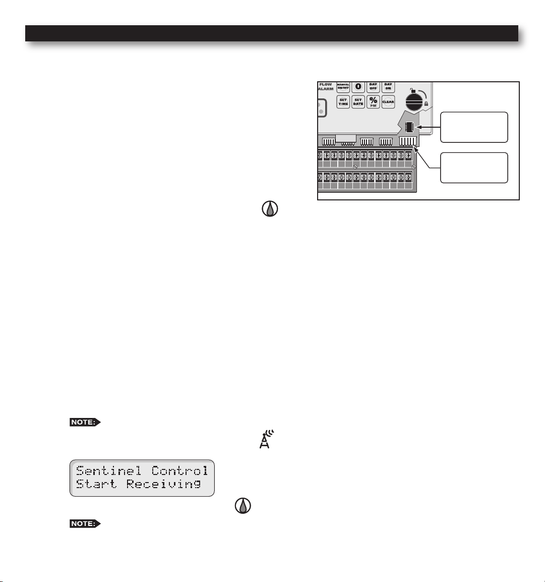
Remote Control (Purchased Separately)
VALVE
COMMON
VALVE
COMMON
The MC-E is equipped with two remote control ports to be used with the Toro SentinelTM Remote Central System and
hand-held maintenance remote controls.
Maintenance Remote Controls
The MC-E can be remotely operated using any of the following
remote control systems:
• KwikStart® Remote (KSR-KIT-K) Control System
• Commercial Maintenance Remote (CMR-KIT) Control System
• Eicon’s Maintenance Remote Control System
• Some models of TRC Irrigation Remotes.
For Irritrol KSR-KIT-K and CMR-KIT:
Step 1 – Verify that the Function dial is in the Auto Run
position.
Step 2 – Secure the remote control system’s receiver cable to the MC-E KSR/CMR remote socket. Remote system such
as the KwikStart will require an adapter cable to install. Refer to the remote control system’s installation and
operation instructions for additional information.
For the Toro Sentinel Remote Central System, Eicon or
TRC Remotes (Sidekick or Commander):
The MC-E controller is designed to be compatible with the Toro Sentinel Remote Central System, Eicon and some of the
TRC remotes.
KSR/CMR
Remote Socket
Sentinel
Remote Socket
When the function dial is placed in the Remote Control position, MC-E will immediately stop all activities and it will
start receiving commands from Sentinel Central, Eicon or some of the TRC remotes. As long as the function dial is in
the Remote Control position, all scheduled programs are ignored and the 5-pin KwikStart Remote (KSR)/Contractor
Maintenance Remote (CMR) port is disabled. The MC-E will only operate based on commands received from Sentinel
Central, Eicon or TRC remotes.
Step 1 – Secure the 6-Pin ribbon data cable from the MC Link remote device to the MC-E Sentinel remote socket.
The other remotes utilizes the 6-pin Sentinel remote socket also.
Step 2 – Place the Function Dial to the Remote Control position. Leave the dial at the remote control position to
keep the MC-E under the control of Sentinel Central, Eicon or TRC remotes.
Step 3 –
Return the Function dial to AUTO/RUN position to exit Sentinel’s Remote Control communication.
Any remote that uses the Sentinel remote socket bypasses the controller’s diagnosotic circuit breaker.
Do not use this type of remote for electrical troubleshooting.
34
Page 35

Flow Sensor (Sold Separately)
VALVE
COMMON
VALVE
COMMON
VALVE
COMMON
MASTER
VALVE
YEL RED
VALVE
COMMON
GND
1 3 5 7 9 11 13 15 17 19 21 23 25 27 29 31 33 35 37 39 41
2 4 6 8 10 12 14 16 18 20 22 24 26 28 30 32 34 36 38 40 42
1 3 5 7 9 11 13 15 17 19 21 23 25 27 29 31 33 35 37 39 41 43 45 47
2 4 6 8 10 12 14 16 18 20 22 24 26 28 30 32 34 36 38 40 42 44 46 48
INHIBIT SENSOR START SENSOR FLOW SENSOR
Flow monitoring is one of the best water resource management tools available in the irrigation industry today. With
denable over and critical ow values, broken lateral or mainline piping, stuck valves and damaged sprinklers can be
quickly detected and bypassed automatically.
The ow sensing capability of the MC-E allows it to learn actual ow rates for every station. These ow rates are stored
in the memory for comparison use. Whenever a station is activated, MC-E will monitor and compare the values to detect
if overow or critical ow values have been violated. The overow percentages are user dened to ne tune the system.
The MC-E is designed to function with a normally open master valve and a ow sensor. The Data Industrial PVC tee
ow sensor model 228PV, 250BR or equivalent are the recommended sensors for use. When MC-E detects a ow value
that violates the station ow parameters, the ow alert LED indicator will illuminate. The MC-E will make an audible
beep every 30 seconds to notify you of the ow error. The controller will also display the problem station on the LCD.
The ow alert indicators will continue until the detected ow is returned within the set parameters and the button is
pressed.
Flow sensing requires that Station 2 is used for a normally-open master valve rather than a
regular station. See Optional Setup.
Flow Sensor Installation
Step 1 – Install the ow meter into the main pipe that only
supplies irrigation to the area being monitored.
Typically, it is installed just before or after the
master valve. Install the ow sensor according to
the provided instructions. Pay particular attention to
the ow direction and to the length of straight pipe
Red Sensor Wire
required before and after the ow sensor. Take note
of the sensor size and the pulse rating for the MC-E
ow sensor setup.
Step 2 – Route a two-wire irrigation cable from the ow
sensor to the MC-E controller. The cable can be
2000 ft. in length when using a shielded twoconductor, 20 AWG or larger stranded copper wire.
Leave extra wire length to allow for future servicing.
Take note which wire is installed to the red sensor
wire as well as the black sensor wire.
Step 3 – At the controller terminals, connect the “Red” wire
to FLOW+ terminal. Connect the “Black” wire to
the FLOW- or SENSOR- terminal. See illustrations.
The controller will beep every 30 seconds
when an ow error is detected.
IMPORTANT! Sensor wires must be installed in the correct polarity for
proper operation. If you plan to use the controller’s ow sensing function,
set ow parameter and learn the ow value for all the stations being used.
MC-E will not execute the ow diagnostic if an active station is without
ow settings even if other active stations have ow settings congured.
FLOW +
FLOW –
Black Sensor Wire
MC-E Models with 18 or more stations
MC-E Models with 12 or less stations
SENSOR – FLOW +
Red Sensor
Black Sensor Wire
Wire
35
Page 36

Flow Sensor Setup
Flow Sensor Overview
The ow sensing system in the MC-E is designed to reduce the risk of ood damage and water waste. As previously
described, the controller requires a properly sized ow sensor in the system. Also, (connected to Station #2 which must be
converted to Flow Alarm) a normally-open master valve is required.
In the SETUP procedure all stations must be set to “MV=ON”.
The controller has an adjustable ow delay, with a default length of 1 minute, to allow the ow to “settle” after a valve
opens. After each valve’s delay period, (settable from 1 to 9 minutes) the controller will monitor the sensor reading.
Because of delay times and the length of the automatic ow diagnostic procedure, station times under 3 minutes
are not recommended when using ow sensing.
The controller can “learn” the correct ow for each irrigation zone in the system. Also, the maximum acceptable ow
limit for the main line can also be set. With the above in place, the MC-E can detect an overow condition for a particular
valve in operation (compared to its learned ow) and shut it off. If the controller can cure the ow problem by turning off
the offending station, it will identify the station with the ow error in its display, illuminate the FLOW ALARM light on
its face panel and beep once every 30 seconds to alert the user. Before moving on to the next station in the program, the
controller will check ow in the main line with all valves off. If no ow, the controller moves on. If ow is detected with
no stations on (catastrophic ow), in addition to the alerts above, the controller will energize and close the normally-open
master valve to shut off the irrigation main line.
While the controller is in
for shut down. Even if you turn the controller to
AUTO/RUN
, but idle, any detected ow with no valves on will also energize station #2
Rain Off
, the MC-E will continue to energize station #2 to keep the
normally-open master valve closed. To clear the ow alert and allow the master valve to open, turn the dial to
FLOW SENSING and press .
Use either STATION TEST or MANUAL to sequence through the stations or to operate a suspect station as you
visually locate the cause of the over ow or unscheduled ow condition. To allow for searching and testing, ow sensing
is not active in STATION TEST or MANUAL modes.
CAUTION:
Flow sensing is active in the controller’s automatic mode for detecting overow conditions in
the remote control valves and mainline catastrophic ow. Other water outlets in the irrigation mainline will cause
unscheduled ow and activate mainline shutdown. To operate quick coupler valves, etc. downstream of the ow sensor,
either disable ow sensing or manually turn on an unused station that has no learned ow. During operation of a station
with no learned ow, ow sensing is disabled.
When the controller is in RAIN OFF , ow sensing is disabled.
Enable/Disable MC-E Flow Sensing
Step 1 – Place the Function dial to the FLOW SENSING position.
Step 2 – If Flow Sensing is not Enabled, the controller will prompt
“Enable Flow? Press DAYOFF”. Press the button to activate
Offset Value Flow Unit
K Value Size Code
ow sensing. The K Value/Size Code screen will be displayed when
ow sensing is successfully enabled:
Step 3 – Deactivate ow sensing by pressing the button.
36
Page 37

Catastrophic Flow Sensor Protection (Optional Setup)
The MC-E provides a function to detect an unscheduled ow. Any detected ow in the system when no station is watering
is considered an unscheduled ow. The MC-E has the capability to monitor any unscheduled ow and activate Station 2
as a ow alarm to shut off a normally open master valve.
The ow alarm can be used to activate a normally open master valve which is installed ahead of the other valves on the
system. Station 2 must be set to ow alarm in SETUP for this to function. The F00 (“F00” represents the upper ow limit
for the main line) parameters in the ow setup will dictate the overow threshold of the main line. When at any time MCE detects an unscheduled ow that violates F00 overow parameters, MC-E will activate station 2 to close the normally
open master valve.
Install Critical Flow Shut off Master Valve
Step 1 – Find a location along the sub-main pipe that services
the irrigation system to install the normally open
master valve. The location should be ahead of any
valves in the irrigation system. Refer to the valves
installation instructions for further details.
Step 2 – Route a two-wire irrigation cable from the valve
to the controller. Connect one solenoid wire to the
valve common terminal and the remaining solenoid
wire to the Station 2 terminal.
Step 3 – Check for proper operation.
Configure Station 2 for Flow Alarm Function
Step 1 – Place the Function dial to the SETUP position.
Step 2 – Press . Station 2 setup screen will be displayed.
Sta 2
COM
Flow
Normally Open
Master Valve
(Station 2)
FLOW +
FLOW – or
SENSOR –
Flow Sensor
Sta 1
Station 1
Station 3
COM
Sta 3
Sta 4
Station 4
Step 3 – Press the button to congure Station 2 as ow alarm to activate a normally-open master valve or press the
button to congure it back to station. Press to activate your selection.
Step 4 – Return the Function dial to AUTO/RUN position.
Catastrophic Flow Parameters
Step 1 – To assign F00’s ow value (Catastrophic ow), place the Function dial to the FLOW SENSING
position. Navigate to the Over percentage limit screen by pressing the button. If F00 is not the displayed
station number, press the button repeatedly until F00 is selected.
Step 2 – Enter the desired catastrophic ow value and press .
Do not set the Catastrophic ow value below the rated minimum ow of your ow sensor or it may
not function properly.
For example: If your ow sensor is rated at 20–300 GPM, DO NOT set the F00 ow value below 20 GPM.
Step 3 – Adjust the catastrophic Overow. See “Set Overow percentages” section.
37
Page 38

Set Flow Sensor Model
Flow Sensor Model K Value Offset GPM L/Sec
Size
Code
Pipe
Size
Unkown Flow Sensor 00 Unkown 1 0 PPS PPS
TFS-050 50 1/2’’ 0.07800 0.9 1.2 – 12 0.1 – 0.8
TFS-075 75 3/4’’ 0.15630 0.9 2.7 – 28 0.2 – 1.8
TFS-100 100 1’’ 0.26112 1.2 5.0 – 50 0.3 – 3.2
TFS-150 or 228PV15xx-xxxx 150 1.5’ 1.69900 -0.3160 5 – 100 0.3 – 6.3
TFS-200 or 228PV20xx-xxxx 200 2.0’’ 2.84290 0.14350 10 – 200 0.6 – 12.6
TFS-300 or 228PV30xx-xxxx 300 3.0’’ 8.30900 0.22700 20 – 300 1.3 – 18.9
TFS-400 or 228PV40xx-xxxx 400 4.0’’ 13.74283 0.23707 40 – 500 2.5 – 31.5
250BR0700x-xxxx 7 3/4’’ 0.43680 0.56800
250BR1000x-xxxx 10 1’’ 0.39740 0.26180
0.25 Liters Per Pulse 11 0.25 L /P 1 0
0.50 Liters Per Pulse 12 0.50 L /P 1 0
1 Liter Per Pulse 13 1 L/P 1 0
2.5 Liters Per Pulse 14 2.5 L /P 1 0
5 Liters Per Pulse 15 5 L/ P 1 0
10 Liters Per Pulse 16 10 L /P 1 0
25 Liters Per Pulse 17 25 L /P 1 0
50 Liters Per Pulse 18 50 L /P 1 0
100 Liters Per Pulse 19 100 L /P 1 0
250 Liters Per Pulse 20 250 L /P 1 0
500 Liters Per Pulse 21 500 L /P 1 0
1000 Liters Per Pulse 22 1000 L/P 1 0
Flow Sensor Data Table
Step 1 – Place the Function dial to the FLOW
SENSING position. Enable
ow sensing if its disabled.
Step 2 – While in the K Value/Sensor Size
screen, select the ow sensor size
code by pressing the button.
Use the Flow Sensor table below to
nd your specic size code.
Example: If using Sensor Model
TFS-075, press the button until
the S value in the display equals 75
(S=75).
Set Flow Unit
Step 1 – Place the Function dial to the FLOW SENSING position. Enable ow sensing if its disabled.
Step 2 – Press the button to change the ow unit. Press the button repeatedly until the desired ow unit is
displayed (GPM = Gallons per Minute, CFM = Cubic Feet per Minute, CMH = Cubic Meter per Hour,
LPM = Liter per Minute or PPS = Pulses per Second).
If the sensor you choose is not represented on the chart, use “Unknown Flow Sensor” size code “00”. The ow
unit for “Unknown Flow Sensor” can only be set to PPS.
Read/Learn Station Flow Value
Step 1 – Place the Function dial to the FLOW SENSING position. Enable ow sensing if its disabled.
Step 2 – Verify that all ow parameters are set, then press the button to read/learn each of the station’s actual
To learn the ow value of a specic station, enter the two digit station number and press the button.
To learn the ow value of a group of stations, enter the two digit station number of the 1st station, the two digit
Step 6 – To review each station ow parameters, press the button. MC-E will sequentially display each of the
ow. It will read/learn the station’s ow value until the ow delay time expires. The default ow delay is one
minute. During “Learn Flow” each station will be displayed with the ow that the sensor is measuring.
station number of the last station and press the button. The MC-E will sequentially read the ow value for
each station in the group.
station’s ow parameters.
38
Page 39

Set Overflow percentages
Step 1 – Place the Function dial to the FLOW SENSING position. Enable ow sensing if its disabled.
Step 2 – Select the station number being edited. While in the K Value/Size Code screen, press the button to advance
to the Overow screen. Press the button to advance the Station number.
Station Number Overow Percentage Limit
Flow Delay (Minutes)
Flow Value (Learned) Flow Unit
Step 3 – Press the button to adjust the Overow percentage . This value will set the maximum ow value limit.
When actual ow reads above the maximum, the ow alarm LED will activate and an audible tone will beep
every 30 seconds. MC-E will also ash in the display which station posted a faulty ow reading.
The factory default Overow percentage is 40%. Underow is not monitored.
Set Flow Delay Time
Step 1 – Place the Function dial to the FLOW SENSING position. Enable ow sensing if its disabled.
Step 2 – Press the button to advance the display to the Underow/Overow screen.
Step 3 – Press the button to adjust the ow delay time. The ow delay time is the period that MC-E will wait
after activating a particular station before reading the ow. This delay period allows the irrigation system to
normalize to get an accurate ow reading. The default ow delay time is set at 1 minute but can be adjusted up
to 9 minutes using .
Step 4 – Press the button to advance to the next station number and adjust the remaining station’s ow delay.
IMPORTANT! Station 2 is no longer a regular station. Leave its settings at 0.
Clear Flow Alarms:
Press the button. Use the procedure below if pressing the button did not clear the alarms.
Temporarily Clear Flow Alarm
Step 1 – To temporarily clear the ow alarm, disable the ow function by placing the function dial to the FLOW
SENSING position
Step 2 – Press the button to deactivate ow. Press the button to reactivate. By deactivating and activating the
ow sensing, it will temporarily stop the ow error beeps and ashing message but MC-E will still retain in
memory which station incurred a ow error. Once that station is reactivated, the ow alarm indicators will
reactivate to remind you that an error occurred.
Permanently Clear Flow Alarm
To permanently clear the ow alarm, simply reactivate the station that returned the ow error.
See “Semi-Auto Operation – Activate Station Manually” for manual station activation. Once MC-E approves that the
station’s ow value is acceptable, the ow alarm is cleared. If the ow problem has not been resolved, the ow error will
return.
39
Page 40

Specications
For Product Inquiries:
U.S.A.
P.O. Box 489
Riverside, California 92502
Tel:(909) 785-3623
(800) 634-8873
Europa
Irritrol Europe s.p.a.
Via dell’Artigianato, 1/3-Loc
Prato della Corta
00065 Fiano Romano (Roma),
Italia
Tel: (39) 0765 455201
Australia
Irritrol PTY Ltd.
53 Howards Road
Beverley, SA 5009
Tel: (08) 8300 3633
Cabinet Dimensions:
Small Metal Cabinet Unit: (9.71” H) x (10.68” W) x (4.25” D) [(24.66 cm H) x (27.13 cm W) x (10.79 cm D)]
Large Metal Cabinet Unit: (12.37” H) x (14.32” W) x (4.75” D) [(31.42 cm H) x (36.37 cm W) x (12.06 cm D)]
Input Voltage:
Domestic: 115 VAC, 50/60 Hz; Secondary - 24 VAC, 50/60 Hz, 50VA Class 2 Transformer, UL and CSA Listed.
Export: 250 VAC, 50/60 Hz; Secondary - 24 VAC, 50/60 Hz, 50VA Class 2 Transformer, CE and TUV Listed.
Output Voltage:
Station Output Voltage: 24 VAC with 1.00 Amp Max
Maximum Master Valve Current: 1.00 Amp
Total Output Current to Valves: Not to Exceed 1.68 Amps including Master Valve/Pump Start
Storage Temperature:
4º F to 140º F (-20º C to 60º C)
Operating Temperature:
32º F to 160º F (0º C to 60º C)
Humidity:
95% RH, Non Condensing, @ 100º F (37.8º C)
Electromagnetic Compatibility
Radio complies with FCC Part 22 and Part 90 of the FCC Rules
Domestic: This equipment has been tested and found to comply with the limits for a FCC Class A digital device, pursuant
to part 15 of the FCC Rules. These limits are designed to provide reasonable protection against harmful interference when
the equipment is operated in a commercial environment. The equipment generates, uses, and can radiate radio frequency
energy and, if not installed and used in accordance with the instruction manual, may cause harmful interference to the
radio communications. Operation in a residential area is likely to cause harmful interference in which case the user will be
required to correct the interference at his own expense.
© 2008 Irritrol • www.Irritrol.com Part Number 373-0478 Revision B
40
 Loading...