

Page 1
T
M
Automatic Sprinkler System Controller
N
E
X
T
N
E
X
T
N
E
X
T
N
E
X
T
N
E
X
T
N
E
X
T
T
M
N
EXTN
EXT
N
EXTN
EXT
N
EXTN
EXT
T
M
User’s Guide
KwikDial Features:
• Three Independent Watering Programs
• Watering Schedule b y 7-Day Calendar,
Day Interval or Odd/Even Days
• Three Start Times Per Program
• Multi-language Display Option
• 24-hour Memory Back-up Without Battery
• Automatic V alve T esting Mode
• Rain Delay Mode
• Remote Control Ready
• Rain Sensor Ready
Español FrançaisEnglish
Outdoor Model
Indoor Model
Page 2

Specifications
Dimensions - Indoor Models
6" W x 9" H x 3" D
(15.3 cm W x 22.9 cm H x 7.6 cm D)
Dimensions - Outdoor Models
6" W x 9" H x 4" D
(15.3 cm W x 22.9 cm H x 10.2 cm D)
Power Specifications:
Indoor Models - Domestic
Plug-in Transformer, Class 2, UL Listed,
CSA Certified (or equivalent)
• Input: 120 V a.c. 50/60 Hz, 0.5 Amps
• Output: 24 V a.c. 50/60 Hz, 20 VA
Outdoor Models - Domestic
Built-in Transformer, Class 2, UL Listed,
CSA Certified (or equivalent)
• Input: 120 V a.c. 50/60 Hz, 0.5 Amps
• Output: 24 V a.c. 50/60 Hz, 20 VA
Indoor Models - Export
Plug-in Transformer, TUV Approved
• Input: 230 V a.c. 50 Hz, 0.1 Amps
• Output: 24 V a.c. 50 Hz, 20 VA
Outdoor Models - Export
Built-in Transformer, TUV Approved, SAA Approved
• Input: 230/240 V a.c. 50/60 Hz, 0.1 Amps
• Output: 24 V a.c. 50/60 Hz, 20 VA
Indoor Models - Australia
Plug-in Transformer, SAA Approved
• Input: 240 V a.c. 50 Hz, 0.1 Amps
i
• Output: 24 V a.c. 50 Hz, 20 VA
Maximum Load Per Station:
0.4 Amps @ 24 V a.c.
Maximum Load For Pump/Master Valve:
0.4 Amps @ 24 V a.c.
Total Maximum Output: One station plus pump,
not to exceed 0.80 Amps @ 24 V a.c.
Temperature Limit Range:
Operating – 14°F to 140°F (-10°C to 60°C)
Storage – -22°F to 149°F (-30°C to 65°C)
Page 3

Table of Contents
KwikDial Components..................................... 2–3
Controller Installation
• Installing the Cabinet ........................................ 4
• Connecting the Valves.................................. 4–5
• Connecting a Pump Start Relay ....................... 5
• Rain Switch Sensor Installation .......................6
• Connecting the Power Source...................... 6–7
Programming...................................................8–13
• Setting the Date/Time....................................... 8
• Planning Your Watering Schedule.................... 8
• Watering Schedule Form............................ 9–10
• About the KwikDial Memory............................11
• Setting a Calendar Day Schedule...................11
• Setting an Odd or Even Day Schedule............11
• Setting a Day Interval Schedule......................12
• Setting Program Start Time.............................12
• Setting Station Run Time Duration..................13
...................................... 4–7
Controller Operations...................................13–15
• Automatic Operation ....................................... 13
• Manual Operations.......................................... 13
• True Manual Operation...................................14
• Timed Manual Operation.................................14
• Manual Program Operation.......................14–15
• Test Mode.......................................................15
• Rain Delay Mode.............................................15
• Turning Off the KwikDial ................................. 15
Special Functions..........................................16–18
• Water Budget..................................................16
• Station Run Time Duration Format ................. 16
• Display Language Option................................ 16
• Clock Time Format Option..............................17
• Program Erase................................................ 17
• Enable/Disable Expansion Port.......................17
Automatic Circuit Breaker.................................17
Troubleshooting
Electromagnetic Compatibility
For Technical Assistance
.................................................18
..........................18
..................................18
ii
Page 4
1
2 3
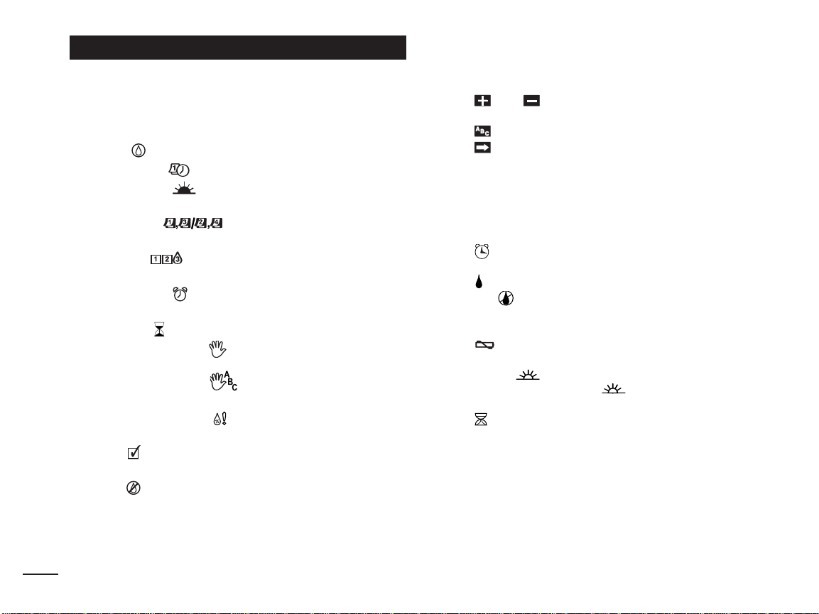
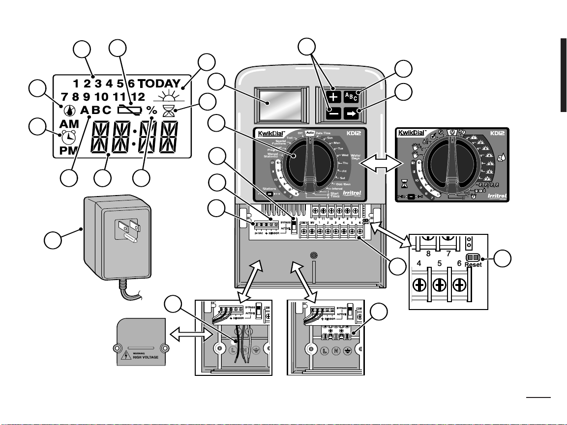
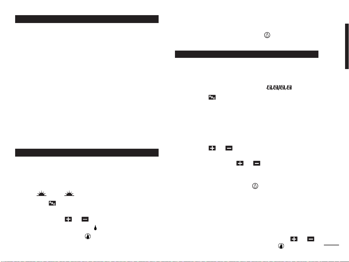
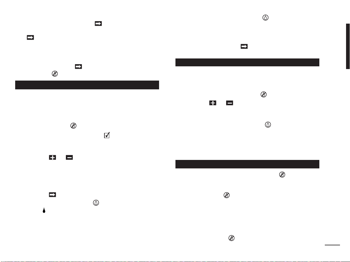
KwikDial Components
1 - LCD Display
2 - Control Dial - Select controller programming and
operating functions.
Control Dial Positions:
Auto - Dial position for automatic operation.
Date/Time - To set the current date and time.
Water Days - To select individual days of the
week for automatic watering.
Odd/Even - To set an Odd or Even
watering day (date) schedule.
Interval - To set a Day Interval watering
schedule.
Start Times - To set start times(s) for automatic
watering program.
Stations
Manual Station(s) - To select station(s) for
manual operation.
Manual Programs - To select watering
programs for manual operation.
Special Functions - To select optional controller
functions.
Test - To run a test program to check station
operation.
OFF - Turns off and prevents all station operation.
3 - Sensor Switch - Active/Bypass switch to control
operation of an optional rain sensor.
4 - Sensor Connection Terminals
5A- Plug-in Transformer Connection Terminals
2
(indoor models only).
- To set station run time duration.
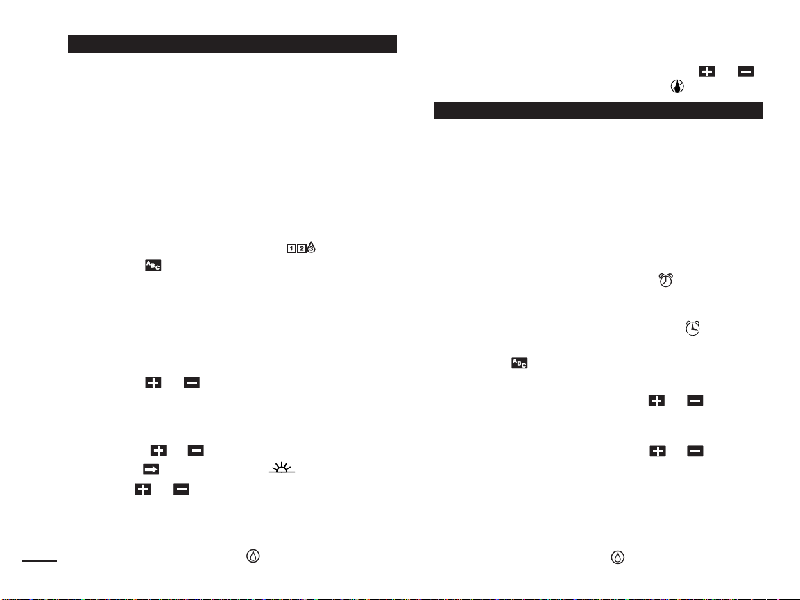
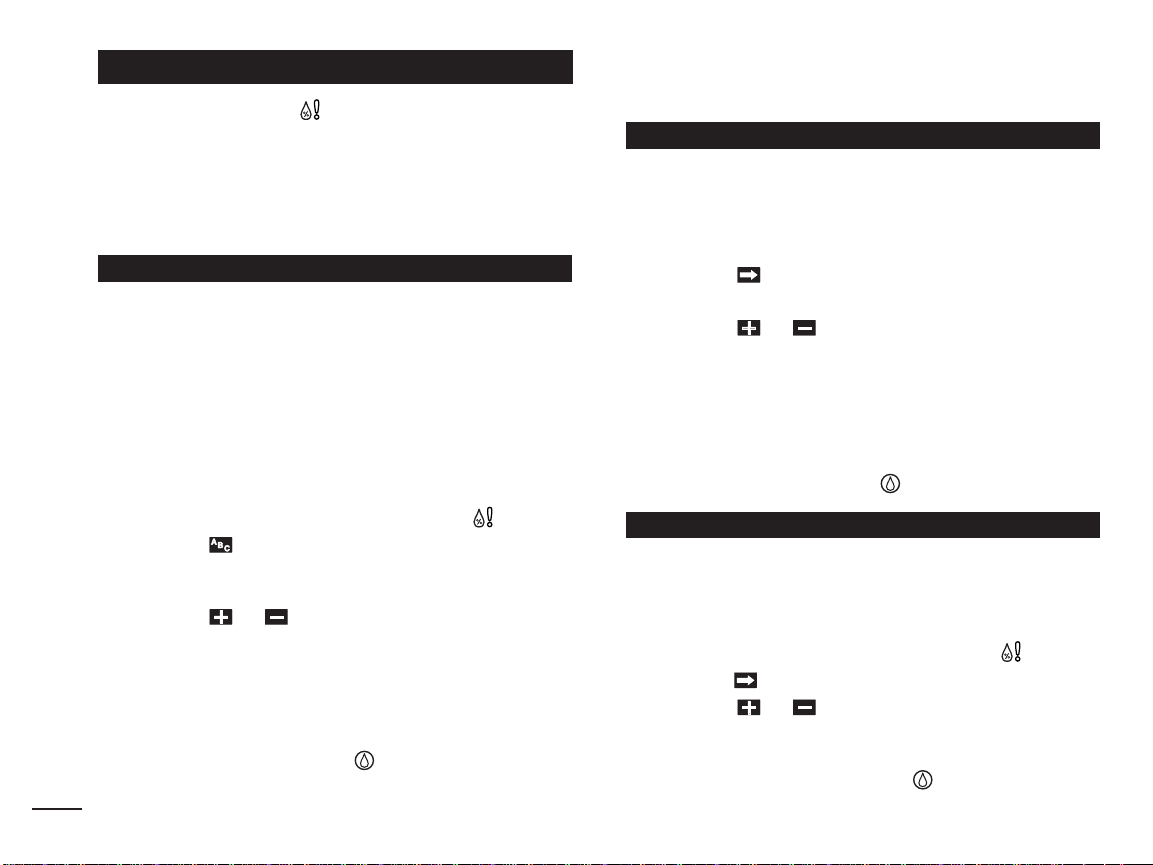
5B- Power Connection Wires (outdoor domestic and
Australian models only)
5C- Power Connection Terminals (outdoor international
models only).
6- and Buttons - Press to increase or decrease
display number values and various manual functions.
7 - Button - Press to select program A, B or C.
8 - Button - Press to advance to next portion of
program information or next station when operating.
9 - Station Terminals - Connection terminals for valve
control wires, master valve or pump start relay wires.
10- Plug-in Transformer (indoor models only) - Supplies
24 V a.c. power to the controller from a grounded
wall plug outlet. (Domestic model shown.)
11- Symbol - Displayed when setting an automatic
watering program start time.
12- Symbol - Displayed when watering is on or set.
The symbol indicates no watering is set.
13- Station Numbers - Displayed when setting program
start time(s) and while a station is running.
14- Symbol - Displayed 30 seconds when charging
back-up power to retain program memory.
15- Today/ Symbol - Displayed when setting a Day
Interval schedule. The symbol is shown when a
language other than English is selected.
16- Symbol - Displayed when setting the station run
time duration.
17- % Symbol - Displayed when a Watering Budget run
time duration adjustment is in use.
18- Main Display - Shows various time values and
controller information.
19- A B C - Program letter identifiers displayed during
programming and operation.
20- Reset Contacts - Momentarily connect the contacts
with a metal conductor such as the tip of a flat
screwdriver to reset all programming parameters to
the factory default settings.
Page 5
3
1
2
3
4
5A
5B
5C
6
7
8
9
19
18
10
15
14
13
12
11
16
17
20
(International Models)
Note: Power connection access
cover removed for illustration.
Troubleshooting.
See
3
Page 6

Controller Installation
Installing the Cabinet
1. For safe, reliable operation, select an installation site
which can ideally provide the following conditions:
• For Indoor model controllers – Inside a garage or
other structure which will provide protection from the
weather.
• For outdoor model controllers – Protection from
irrigation spray, wind and snow. A shaded location is
recommended.
• Access to a grounded AC power source (within 4'
[1.2 m] for indoor models) which is not controlled by
a light switch or utilized by a high current load
appliance, such as a refrigerator or air conditioner.
• Access to the sprinkler control valve wiring and
optional accessory wiring.
2. Drive a wood screw (provided) into the wall at eye
level (A). Leave the screw extended approximately
(6 mm) from the wall. See Figure 1.
Note: If installing the controller on drywall or
masonry, install screw anchors. Install the lower
screw anchor 51⁄4" (133 mm) directly below the top
screw anchor.
3. Remove the lower cabinet access cover by squeezing
it in on the sides and pulling it directly outward from
the cabinet.
4. Hang the cabinet on the screw using the keyhole slot
on the back panel (B). Make sure the cabinet slides
down securely on the screw.
4
5. Install the lower mounting screw and tighten securely.
Figure 1
B
A
C
D
Note: Conduit and adapters are not provided. Install
conduit as required by local electrical codes.
6. Remove the power wire access cover. Remove the
conduit knockout according to the size of conduit
1
being used. Install
⁄2" (13 mm) conduit (C) for
power/equipment ground wires (outdoor models only)
1
⁄4"
and 3⁄4" (19 mm) or 1" (26 mm) conduit (D) for valve
wires (all models).
Connecting the Valves
1. Route the valve wires or wire cable from the valves,
into the controller cabinet.
Note: 18 AWG (1.0 mm2) multi-wire sprinkler valve
connection cable can be used. This cable is insulated
for direct burial and is color-coded to simplify
installation. It can be routed directly into the controller
through the access hole provided for valve wire
conduit (if conduit is not used).
2. Attach the white color-coded wire from the cable to
from each valve solenoid. (Either solenoid
wire
one
Page 7

Figure 2
MV
Valve 1
Valve Common Wire
Valve 2
Valve 3
Connecting a Pump Start Relay
CAUTION: To prevent controller damage, ensure
the pump start relay current draw does not exceed
0.4 amps. Do not connect the pump motor starter
directly to the controller.
1. Connect a wire pair to the 24 V a.c. pump start relay.
Route the wires into the controller housing with the
valve wires.
2. Connect one wire to the terminal labeled
Connect the remaining wire to the terminal labeled
See
Figure 3.
COM/VC.
MV.
wire can be used for this connection.) This is called
the “Valve Common” wire. See
Figure 2.
3. Attach a separate cable wire to the remaining wire
from each valve solenoid. Note the wire color code
used for each valve and the watering station it
controls. You will need to have this information when
connecting the valve wires to the controller.
4. Secure all wire splices using wire nut connectors. To
prevent corrosion and possible short circuits, always
use an insulated wire nut, grease cap or similar
waterproofing method.
5. At the controller end of the valve connection cable,
strip back
1
⁄4" (6 mm) of insulation from all cable wires
6. Secure the Valve Common wire to the terminal labeled
COM/VC. Connect the individual valve wires to the
appropriate station terminals. Connect the master valve
wire (if applicable) to the terminal labeled
MV.
Note: Connecting a master valve or pump start relay
is optional and may not be required for your sprinkler
system.
Figure 3
Jumper Wire
Valve 3Valve 2
CAUTION:
Pump Start
Relay
Valve Common Wire
Valve 1
To prevent pump damage due to
“Dead-heading,” connect a jumper wire from any
unused station terminal to a station terminal with a
valve connected. See Figure 3.
5
Page 8
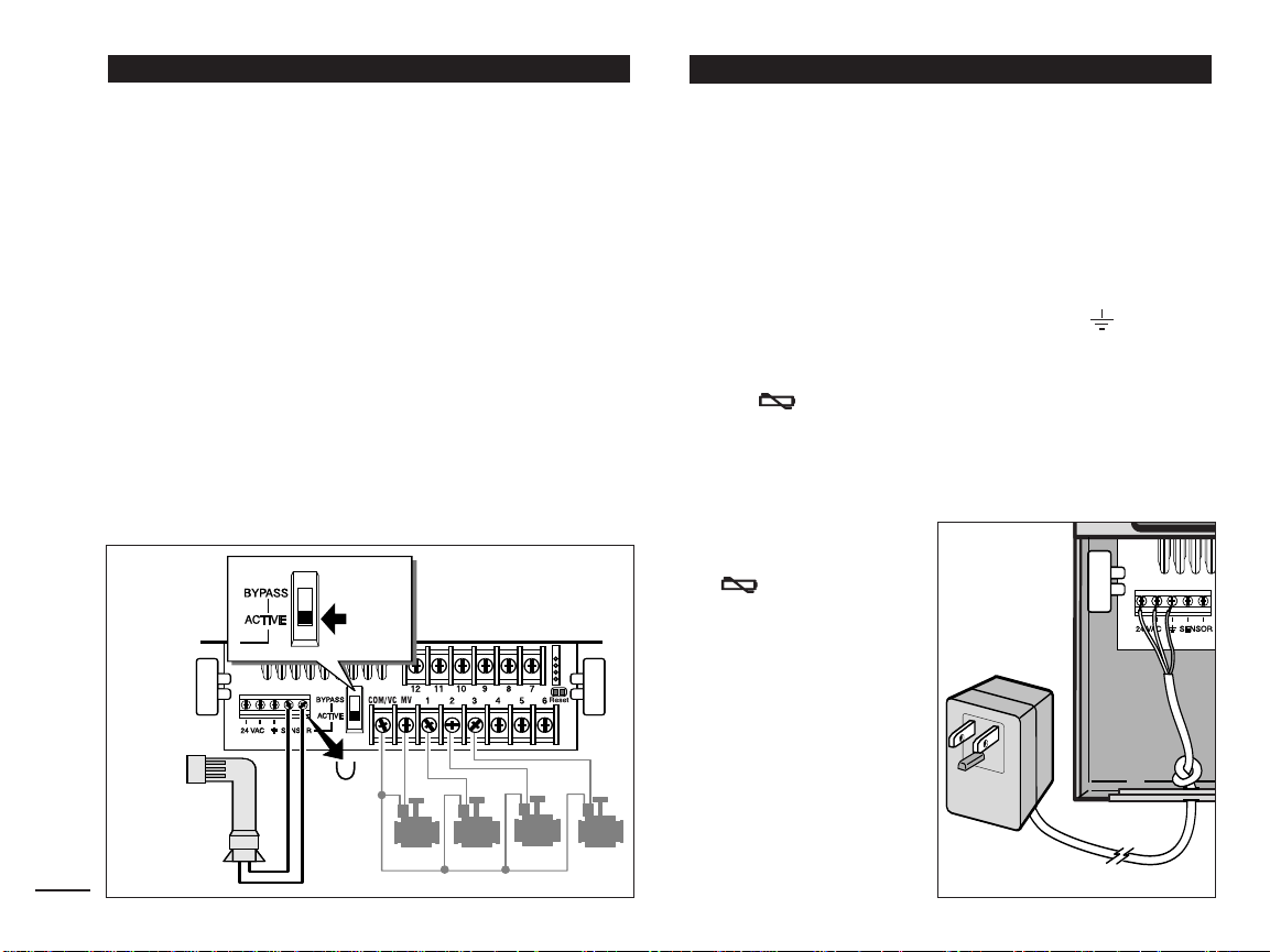
A rain sensor can be connected directly to the KwikDial
to automatically interrupt watering when it begins to rain.
When the rain sensor absorbs rain water, it automatically
signals the KwikDial to suspend all watering operations.
The display will alternately show “SEN” (sensor) and the
time of day until the rain sensor drys out and resets the
controller for automatic operation.
1. Route the wire cable from the rain switch sensor into
the controller along with the valve wires.
2. Remove the jumper wire from the sensor terminals.
3. Referring to the instructions provided with the rain
sensor, connect two wires from the rain sensor
designated for “Normally Closed” applications to the
sensor terminals. See
4. Place the sensor switch to the
Figure 4.
ACTIVE position. To
turn off the sensor circuit, place the switch in the
BYPASS position. See Figure 4.
Figure 4
Rain Sensor
Sensor
Switch
Jumper
Wire
6
Connecting the Power SourceRain Sensor Installation (optional)
Indoor Models
1. Route 6" (15 cm) of the transformer wire cable into
the controller through the small opening provided in
the base of the cabinet.
2. Tie a knot in the cable just inside the cabinet to prevent
the cable wires from pulling out. See
Figure 5.
3. Connect the transformer cable red and black wires to
the terminals labeled “24 VAC”. Connect the green or
green/yellow wire to the ground terminal .
Figure 5.
See
4. Plug the transformer into the wall plug socket.
The symbol will be displayed for 30 seconds while
the program memory back-up power is being charged.
During this time, the controller can not be operated.
This will only occur when the controller is initially
powered up or after a power interruption.
When the controller is
Figure 5
ready to operate, the
symbol will
disappear and
4:00 PM
will be displayed. See
“Setting the Date/Time”
on page 8 to set the
current time and date.
To quickly check the
sprinkler system
operation, refer to the
“Test Mode” procedure
provided on page 15.
Page 9
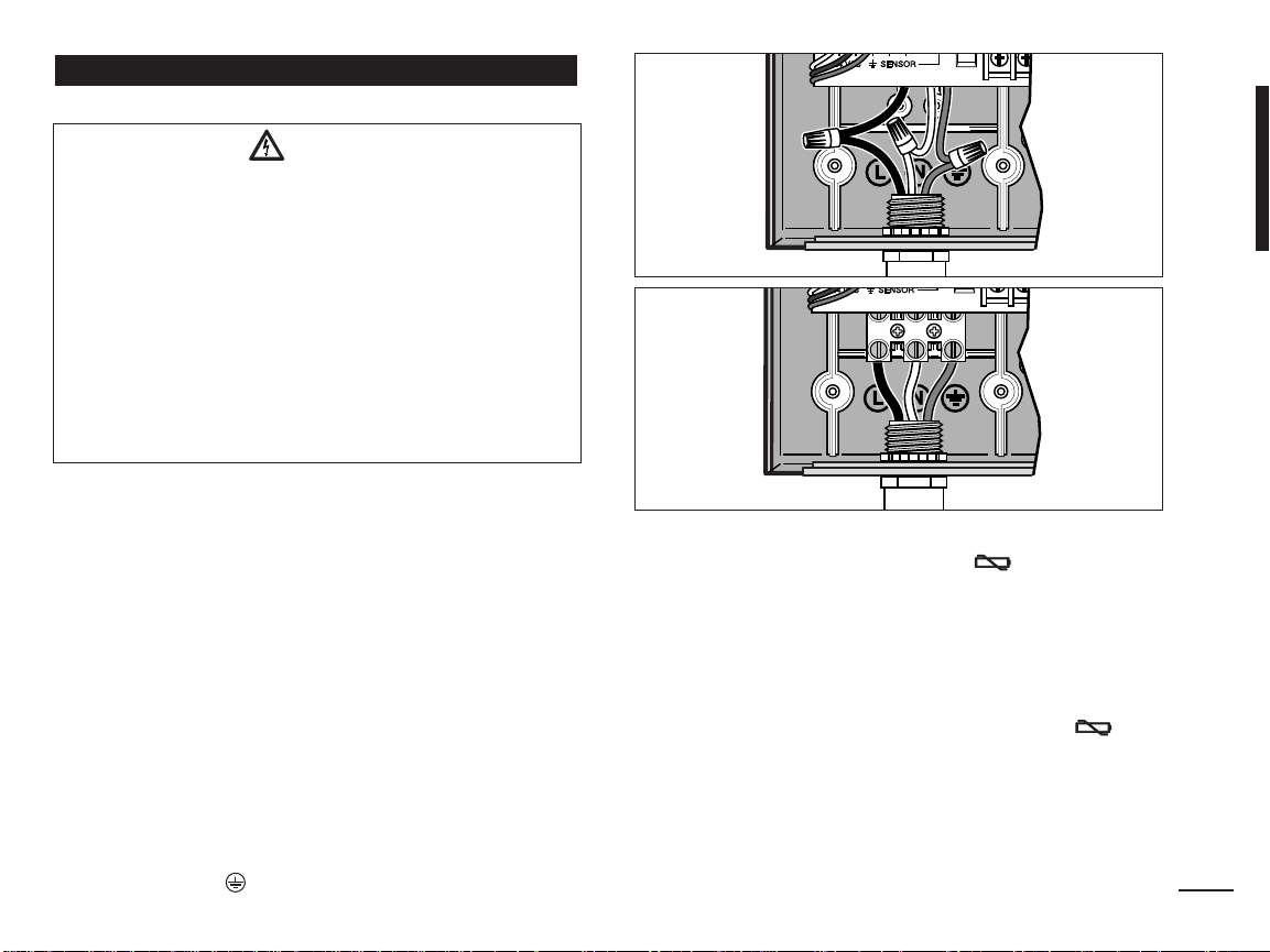
Connecting the Power Source (continued)
Outdoor Models
WARNING
AC power wiring must be installed and connected
by qualified personnel only. All electrical
components and installation procedures must
comply with all applicable local and national
electrical codes. Some codes may require a means
of disconnection from the AC power source
installed in the fixed wiring and having a contact
separation of at least 0.120" (3mm) in the line and
neutral poles.
Make sure the power source is OFF prior to
connecting the controller.
1. Verify that the power is turned off at the source.
2. Remove the power connection access cover.
3. Route the power and equipment ground wires from the
power source through conduit into the controller power
connection compartment.
Note: The international model terminal block accepts
wire size up to 4 mm2.
4. For domestic and Australian models, refer to
Using the wire nuts provided, secure Line to the Black
wire, Neutral to the White wire and Equipment Ground
to the Green wire.
For international models, refer to
(10 mm) insulation from the wire ends. Using a small
flat blade screwdriver, secure Line o r L i n e 1 t o L ,
Neutral or Line 2 to N and Equipment Ground to the
ground terminal .
Figure 7. Remove 3⁄8"
Figure 6.
Figure 6
Figure 7
5. Install and secure the power wire access cover.
6. Apply power to the controller. The symbol will be
displayed for 30 seconds while the program memory
back-up power is being charged. During this time, the
controller can not be operated. This will only occur
when the controller is initially powered up or after a
power interruption.
When the controller is ready to operate, the
symbol will disappear and
See “Setting the Date/Time” on page 8 to set the
current time and date. To quickly check sprinkler
system operation, refer to the “Test Mode” procedure
provided on page 15.
4:00 PM will be displayed.
7
Page 10
Programming
Note: To select an optional display language or clock
format, refer to “Display Language Option” on page 16.
Setting the Date/Time
1. Turn the control dial to the
2. Adjust the clock to the current hour by pressing
the or buttons.
Note: The display will change rapidly if either button
is pressed for more than three consecutive seconds.
3. Press the button to advance to the next field.
4. Adjust the display by pressing the or buttons.
5. Repeat steps 3–4 to adjust the remaining fields of the
Date/Time display.
6. Return the control dial to the
finished.
Planning Your Watering Schedule
It is often helpful to plan your watering schedule on paper
before beginning the programming steps. The information
can then be transferred to the Quick Reference Card as a
handy reference.
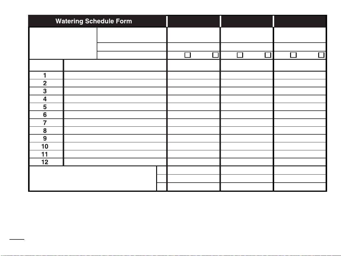
Filling out the Watering Schedule Form
When filling out the form provided on page 10, use a
pencil so changes can be easily made.
Refer to the example shown on the opposite page and fill
out your form in a similar manner. Include the following
information:
Location - Identify the location of each watering
•
8
station area and the type of plant being watered.
Date/Time position.
Auto position when
Note: Enter the following information for each
program. If the program is not needed, leave its
information column blank.
Watering Day Schedule - For a Calendar schedule,
•
indicate which day(s) of the week watering is desired.
For a Day Interval schedule indicate the desired
Interval number (1–31). For Odd or Even day watering
schedule, simply mark the appropriate box.
Station Run Time Duration - Indicate the amount of
•
run time (1 minute to 4 hours) for each station. Write
“Off” for any station which you do not want to run in the
program.
Program Start Times - Indicate the time(s) of day to
•
start the program. Each program can have up to three
start times per watering day.
Important: The KwikDial can run only one program
watering cycle at a time. Therefore, when setting more
than one start time for a program or when setting up more
than one program, make sure that each program watering
cycle will be able to run completely before the next start
time occurs. This can be easily determined by totaling up
the run time duration of all stations that will operate during
the program, then selecting the next start time that can
accommodate the completion of the initial watering
program. If Water Budget is used to increase run time
duration, this must also be considered in the total run time.
It is important to remember that a program start time
which occurs while a watering cycle is in progress will
be delayed (stacked) until the current watering cycle is
finished
are not shutting off or that they are running at an
unexpected time of day. Refer back to this information
when setting program start times as described on page 12
and Water Budget on page16.
. If this happens, it may appear that the sprinklers
Page 11
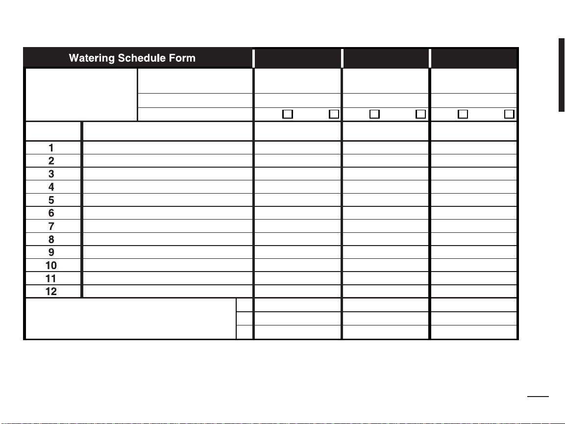
Program Start Times
Watering Day Schedule
Day Interval
Calendar Days
Odd
Odd/Even
Even
1
2
3
Odd Even Odd Even
Station
Location
Run Time Run Time
Run Time
Program A Program B Program C
(Example)
Parkway Lawn 10 min Off Off
Front Lawn 10 min Off Off
2-day 3-day
Tue & Fri
Front Shrubs Off 5 min Off
Back Lawn 25 min Off Off
Garden Off Off 1 hour
5:00 AM 4:00 AM 6:00 AM
Off Off Off
Off Off Off
9
Page 12
Program Start Times
Watering Day Schedule
Day Interval
Calendar Days
Odd
Odd/Even
Even
1
2
3
Odd Even Odd Even
Station
Location
Run Time Run Time
Run Time
Program A Program B Program C
10
Page 13
2 312 3
About the KwikDial Memory
The KwikDial retains a permanent watering schedule
which enables the controller to run the sprinkler system
automatically when first powered up or if a power outage
lasting longer than 24 hours has erased the KwikDial’s
programmable memory. This permanent memory feature
enables your landscape to continue being watered if a
prolonged power outage occurs while you are away.
You may use the permanent schedule as is if it suits
your landscape watering needs. Just set the current time
and date and the KwikDial is ready to control your
sprinkler system automatically.
The permanent schedule operates as follows:
The clock time is set to 4:00
PM, current day is Tuesday
and the date is January 1, 2002. All stations will operate in
sequence on Program A for 10 minutes. Programs B and
C are off. Every day is active in the Calendar schedule,
and one program start time occurs at 5:00 AM.
Setting A Calendar Day Schedule
The Calendar Day schedule enables you to set each day
of the week as an active or inactive watering day. Each day
can be active or inactive in each program (A, B and C).
1. Turn the control dial to the desired day position
Sun , Mon , etc.).
(
2. Press the button as needed to select the desired
program. Program letter
A, B or C will be displayed.
3. Press either the or button to make the day
active (the watering symbol is displayed) or inactive
(the no-watering symbol is displayed) for the
selected program.
4. Repeat steps 1 and 3 for each day of the week.
5. Repeat steps 1–4 for each program as needed.
6. Turn the control dial to the
Auto position when
finished.
Setting An Odd Or Even Day Schedule
Using an Odd or Even Day watering schedule enables
either odd numbered days (1st, 3rd, etc.) or even
numbered days (2nd, 4th, etc.) to be selected to water.
1. Turn control dial to the
Odd/Even position.
2. Press the button as needed to select the desired
program. Program letter
A, B or C. will be displayed.
Note: If Int is displayed, a Day Interval watering
schedule is already selected for the program and
must first be made inactive before an Odd or Even
day schedule can be selected. Refer to “Setting A
Day Interval Schedule” on page 12 for this procedure.
3. Press the or button to display
Odd or Even.
• To remove an Odd or Even Day schedule from the
program, press the or button to display
------ (dashes).
4. Repeat steps 2 and 3 for each program as needed.
5. Turn control dial to the
Auto position when finished.
Note: Since the first day of every month is an odd
number, the last day of every month which is an odd
number will not be active. This feature prevents two
consecutive watering days from occurring.
Note: To prevent watering on specific days of the week,
regardless of schedule type; i.e., never water on Saturday,
turn the control dial to that day and press the or
button to display the no-watering symbol .
11
Page 14
Setting A Day Interval Schedule
A Day Interval schedule enables watering days to be set
without regard to the actual days of the week. For
example, a 1-day interval will water every day, a 2-day
interval will water every other day and so on up to a
31-day interval, which will water only once a month.
The active watering day is the last day of the Interval.
In order to establish a reference point for the beginning
of the Day Interval, the current day within the interval is
also entered. For example, if a 3-day interval is selected
and “Today” is entered as day 2 of the interval, then
watering will occur tomorrow (the last day of the interval).
1. Turn the control dial to the
Interval position.
2. Press the button as needed to select the desired
program. Program letter
A, B or C will be displayed.
Note: If Odd or Even is displayed, an Odd/Even
watering day schedule is already selected for the
program and must first be made inactive before a Day
Interval schedule can be used. Refer to “Setting An
Odd/Even Day Schedule” on page 11 for this procedure.
3. Press the or button to select the desired
interval number (
01–31). The letters DY (day) are
displayed to the right of the Day Interval number.
• To remove an Interval schedule from the program,
press the or button to display
4. Press the button.
TODAY or will be displayed.
------ (dashes).
5. Use the or button to select the Today number
designation.
DY (day) is displayed to the left of the
Today number.
6. Repeat steps 2–5 for each program as needed.
12
7. Turn the control dial to
Auto position when finished.
Note: To prevent watering on specific days of the week,
regardless of schedule type; i.e., never water on Saturday,
turn the control dial to that day and press the or
button to display the no-watering symbol .
Setting Program Start Time
The program start time is the time of day you select to
begin an automatic watering program cycle. When a
program starts, each station with a designated run time
duration in the program will operate in numerical order,
one station at a time. Sometimes it is necessary to run a
watering program more than once per day. For example,
when watering a new lawn. The KwikDial provides three
independent start times per day for each program. Refer
to page 8 for additional program start time information
1. Turn the control dial to
Start Times 1, 2 or 3
position. All station numbers with a designated run
time in the selected program will be indicated at the
top of the display. The start time symbol will be
displayed in the lower left corner.
2. Press the button as needed to select the desired
program. Program letter
A, B or C will be displayed.
3. Set the start time by pressing the or button.
Note: The display will change rapidly if either button is
pressed for more than three consecutive seconds.
• To remove a start time, press the or button to
display
clock display passes from 5:59
------ (dashes). The dashes are shown as the
AM, 11:59 AM, 5:59 PM
and 11:59 PM (05:59, 11:59, 17:59 and 23:59).
4. Repeat steps 1 and 3 for each additional start time.
5. Repeat steps 1–4 for each program as needed.
6. Turn the control dial to
Auto position when finished.
Page 15
Setting Station Run Time Duration
The station run time duration is the amount of time a
station will operate once it has been started. A station is
assigned to a program when it is given a designated run
time duration ranging from 1 minute to 4 hours. Each
station can have a different run time duration in each
program.
Note: You have the option to view station run time duration
in minutes only or in hours and minutes. By default, the run
time will be displayed in the minutes format; i.e., 1 hour
and 30 minutes is displayed as 90M (minutes). To select
the alternate format, refer to “Station Run Time Duration
Format Option” on page 16.
1. Turn the control dial to the desired
position. The selected station number and the station
run time duration symbol will be displayed.
Note: For KwikDial controllers with more than six
stations, use the button to switch from the inner
labeled stations (1–6) to the outer labeled stations
(7–9 or 7–12).
2. Press the button as needed to select the desired
program. Program letter
3. Adjust the station run time duration by pressing the
or buttons.
• To remove the station from the program, decrease
the run time duration to less than 1 minute to
display
4. Repeat steps 1 and 3 to set the run time duration for
each station as needed for the selected program.
5. Repeat steps 1–4 for each program as needed.
6. Turn the control dial to
-- -- -- (dashes).
A, B or C will be displayed.
Auto position when finished.
Station number
Controller Operation
The KwikDial controller has five modes of operation:
Automatic, Manual Station(s), Manual Programs, Test
and Off. In the Automatic mode, the controller tracks the
time and day and operates the automatic watering
schedules as programmed. The Manual Station(s) mode
enables an individual station or group of stations to be
started and controlled manually. Manual Programs mode
enables watering programs to be started manually. Test
mode enables a quick, temporary program to be run to
test the operation of each station control valve. The Off
mode prevents all station operation.
Automatic Operation
Automatic operation will occur whenever the
programmed start time and watering day matches the
KwikDial’s internal clock and calendar.
Auto control dial position is the normal position
The
for the dial when automatic operation is desired.
However, the controller will operate automatically when
the control dial is in any position other than
While an automatic watering program is running and the
control dial is in the
button will manually advance from the activate station to
the next displayed station number in sequence
Manual controller operations will override all currently
active automatic operation and sensor input. Any
automatic program start time that occurs during a
manual operation will be delayed until the manual
operation is terminated or concluded. Any automatic
program delayed past midnight will be postponed.
Auto position, pressing the
Manual Operations
Off .
13
Page 16
True Manual Operation
True manual operation allows a single station to be
selected and run without regard to run time duration. Once
started, the station will run until it is turned off or the
controller clock time passes midnight.
1. Turn the control dial to
2. Press the button until the desired station number
is flashing and the display shows
3. Press the button once to activate the station. The
station number and
flashing watering symbol . Leave the dial in the
Manual Station(s) position. The station will remain on
until operation is terminated or until midnight.
• To terminate operation prior to midnight, turn the
control dial to any other position.
4. Turn the control dial to
Timed Manual Operation
Timed manual operation enables any stations to be
given a temporary station run time duration and operated
in sequence.
1. Turn the control dial to
2. Press the button until the desired station number
is flashing and the display shows
3. Press the or button to select a temporary
station run time duration from 1 to 240 minutes.
Note: The temporary station run time will not affect
the station’s run time within any automatic program.
4. Press the button to select the station.
5. Repeat steps 2–4 to select additional stations.
14
(These stations will not start immediately, but will
operate in sequence.)
Manual Station(s) position.
------ (dashes).
ON will be displayed along with the
Auto position when finished.
Manual Station(s) position.
------ (dashes).
6. After all desired stations for timed manual operation
have been selected, turn control dial to the
position.
• To manually advance through the station sequence,
press the button (the control dial must be in the
Auto position to use this feature).
• To terminate the timed manual operation, either skip
through the remaining station sequence with the
button, or turn control dial to the
for at least three seconds.
Manual Program Operation
Manual program operation enables automatic watering
programs to be manually started and operated in
sequence.
1. Turn the control dial to the
position. The display will show MAN, the currently
selected program letter and stations assigned to the
program.
2. Press the button as needed to display a program
you wish to run. All stations which currently have a
station run time duration assigned to the selected
program will be shown at the top of the display.
3. Press the button to start the program (or select an
additional program). The program letter and the
watering symbol will begin flashing.
4. Repeat steps 2 and 3 to select additional programs to
operate in sequence.
5. Turn the control dial to the
remaining run time duration for the currently operating
station will be displayed. Station numbers and programs
waiting to run will also be shown.
Manual Programs
Auto position. The
Off position
Auto
Page 17
• To manually advance through the station sequence,
for the program, press the button. If more than
one program was selected, continue pressing the
button to advance to the next program in
sequence.
• To terminate the manual program operation, either
skip through the remaining stations and programs in
sequence with the button, or turn the control dial
Off position for at least three seconds.
to the
Test Mode
Selecting this function enables you to run a quick,
temporary watering program to test the operation of each
watering station.
Note: To terminate the test mode at any time, turn the
control dial to the
1. Turn the control dial to the
display will show 2M for a 2-minute run time for each
station.
2. Press the or button to change the run time
from 1 to 9 minutes if desired.
Note: The run time used in the test program is
temporary and will not alter the station run time set for
automatic program operation.
3. Press the button to start the test.
4. Turn the control dial to
symbol and the operating station number will be
flashing. The remaining station numbers to be tested
will be displayed. As the test time is completed for
each station, the station number disappears and the
next station in sequence starts.
Off position for three seconds.
Test position. The
Auto position. The watering
• By leaving the dial in the
controller completes the test of each station then
returns to the Automatic mode.
• To manually advance to the next station in
sequence, press the button. Advancing past the
last station will end the test program.
Auto position, the
Rain Delay Mode
This feature enables all automatic watering operations to
be delayed from 1 to 7 days. When the number of delay
days elapses, the controller returns to automatic operation.
1. Turn the control dial to the
2. Press the or button to select the desired
number of rain delay days (
displayed with
3. Turn the control dial to the
number of rain delay days remaining will be displayed
alternately with the current time of day.
• To terminate the rain delay operation at any time,
repeat steps 1–3 to display
OFF; i.e. OFF 2 for a 2-day delay.
Off position.
1–7). The number will be
Auto position. The
OFF.
Turning Off the KwikDial
When the control dial is turned to the
OFF will be displayed and will flash for three seconds.
The three-second delay allows the control dial to be
turned past the
initiating the Off command. When
any watering operation currently in progress will be
turned off and programmed automatic operation will be
prevented.
For extended shutdown of the sprinkler system, leave the
control dial in the
until the control dial is turned to another position.
Off position momentarily without
Off position. OFF will be displayed
Off position,
OFF stops flashing,
15
Page 18
Special Functions
The Special Functions dial position provides access
to various control features and optional display formats.
The special functions are: Water Budget, Station Run
Time Duration Format Option, Display Language Option,
Clock Time Format Option, Program Erase and
Enable/Disable Expansion Port.
Water Budget
Water Budget enables you to conveniently decrease or
increase the run time duration currently set for each
station assigned to a selected program. The adjustment
can be made in 10% increments from 0% (program Off)
to 200% of the normal (100%) run time.
Note: Water Budget is applied to programs A, B and C
independently. For example, applying Water Budget to
program A will not alter the run time duration of any
stations assigned to Program B or C.
1. Turn control dial to the
2. Press the button as needed to select the desired
program. The currently set percentage for the
program will be displayed.
3. Press the or button to select the desired
adjustment percentage; i.e., 90% equals a 10%
reduction of station run time and 200% doubles the
station run time.
4. To apply Water Budget to another program, repeat
steps 2 and 3.
5. Turn control dial to the
16
Note: During operation, the display will show the
adjusted run time for each station as it starts running.
Special Functions position.
Auto position when finished.
As a reminder of Water Budget setting (other than 100%),
the
% symbol will be displayed with the current time.
See “Important” on page 8 for additional information.
Station Run Time Duration Format Option
The station run time duration can be displayed in either
minutes or hours and minutes format. To change the
current run time format, use the following procedure:
1. Turn the control dial to the
2. Press the button as needed to display
HH:MM.
3. Press the or button to select the desired
format:
MMM = minutes; i.e., 1 hour and 30 minutes is
displayed as 90M.
HH:MM = hours and minutes; i.e., 1 hour and 30
minutes is displayed as 1:30.
4. Turn control dial to the Auto position when finished.
Display Language Option
Various display information can be viewed in any of five
languages: English, Spanish, French, German or Italian.
To change the display language, use the following
procedure:
1. Turn control dial to the
2. Press the button as needed to display
3. Press the or button to select the desired
language:
DEU (German).
or
4. Turn the control dial to the
finished.
ESP (Spanish), FRA (French), ITA (Italian)
Special Functions position.
MMM or
Special Functions position.
ENG.
Auto position when
Page 19

Clock Time Format Option
Time of day can be displayed in either 12-hour AM/PM
or 24-hour format.
1. Turn control dial to the
2. Press the button as needed to select the clock
time format option designated by
3. Press the or button to display the desired
format.
4. Turn control dial to the
The Program Erase feature enables you to easily clear
the controller memory of all
run time duration
selected program or all programs without changing the
current time, date and language option.
1. Turn control dial to the
2. Press the button as needed to display
3. Program
button once to select program
again to select program
selects programs
4. Press the to display the program letter(s) and
5. Press button to clear the program(s) (
displayed) or press the button to cancel.
6. Repeat steps 3–5 to clear any remaining program(s)
as needed.
7. Turn control dial to the
A will be displayed. If needed, press the
Special Functions position.
12H or 24H.
Auto position when finished.
Program Erase
program start times, station
and water budget information for a
Special Functions position.
CLR.
B. Press the button
C. Pressing the button again
A, B and C.
OK?.
CLR will be
Auto position when finished.
Enable / Disable Expansion Port
Your KwikDial controller is capable of remote control
operation when used in conjunction with the KwikStart
remote system. The expansion port provided for the
remote receiver connection must be switched On to
enable KwikStart remote control operation.
1. Turn control dial to the
2. Press the button as needed to select
the expansion port switch option designated by
3. Press the or button to select
port on), or -- (expansion port off).
4. Turn control dial to the
Special Functions position.
XP --.
Y (yes, expansion
Auto position when finished.
Automatic Circuit Breaker
The KwikDial controller features an electronic circuit
breaker which automatically detects an overload
condition on a station terminal during operation and turns
off the station before controller damage can occur. The
KwikDial advances to the next programmed station in
sequence to continue the watering cycle.
After the program watering cycle has finished,
the number of the skipped station(s) will be displayed
in alternating sequence with the current time of day.
When all station numbers and FUSE are displayed, the
master valve is malfunctioning. Pressing the button
will remove the warning display.
Important: The most common cause of an overload
condition is a short circuit in the valve wiring or a
malfunctioning valve solenoid. The cause of the overload
condition should be corrected before continuing to operate
the controller.
FUSE and
17
Page 20

Troubleshooting
Symptom
Display is blank and controller does
not operate.
Probable Cause
Power is disconnected.
Remedy
Check transformer connections (indoor
model). Check the AC service panel for
a tripped circuit breaker or GFI and
reset.
Display not responding to commands
(frozen).
Microprocessor stopped.
Connect “Reset” contact momentarily
with the tip of a flat bladed screwdriver.
The display will blink; controller is reset
to default program. See page 3.
Valve does not turn on.
Faulty control valve wire connections.
Check the wire connections at control
valve and controller.
Sensor switch in Active position without
Set sensor switch to Bypass position.
a sensor or jumper installed.
Valve does not turn off.
No station run time duration set.
Control valve problem.
Check station run times. See page 13.
Inspect, clean and/or replace the valve
solenoid and/or diaphragm.
Watering program(s) start at
unexpected times.
Watering program schedules have
overlapping start times.
Check program start time schedules.
Shorten station run times and/or space
start times farther apart.
See pages 8, 12 and 13.
Water Budget setting over 100% can
cause delayed start times.
Check Water Budget and decrease
adjustment % factor as necessary.
See pages 8 and 16.
Electromagnetic Compatibility
Domestic: This equipment has been tested and found to comply with the limits for a Class B digital device, pursuant to Part 15 of the FCC Rules. These limits are designed to provide reasonable
protection against harmful interference in a residential installation. This equipment generates, uses and can radiate radio frequency energy and, if not installed and used in accordance with the
instructions, may cause harmful interference to radio communications. However, there is no guarantee that interference will not occur in a particular installation. If this equipment does harmful
interference to radio or television reception, which can be determined by turning the equipment off and on, the user is encouraged to try to correct the interference by one or more of the following
measures:
1. Reorient or relocate the receiving antenna.
2. Increase the separation between the equipment and receiver.
3. Connect the equipment into an outlet on a circuit different from that to which the receiver is connected.
4. Consult the dealer or an experienced radio/TV technician for help.
International: This is a CISPR 22 Class B product.
For Technical Assistance:
USA - (951) 785-3623 • (800) 634-8873
Europe - (39) 0765 40191
Australia - 1300 130 898
© 2005 Irritrol Form Number 373-0239 Rev. C
Page 21

T
M
Programador del sistema de riego automático
N
E
X
T
N
E
X
T
N
E
X
T
N
E
X
T
N
E
X
T
N
E
X
T
T
M
N
EXTN
EXT
N
EXTN
EXT
N
EXTN
EXT
T
M
Guía del usuario
Características del programador KwikDial:
• Tres programas de riego totalmente
independientes
• Plan de riego de 7 días calendarios,
de intervalo de días o de días impares/pares
• Tres horas de arranque por programa
• Opción de pantalla en múltiples idiomas
• Respaldo de memoria de 24 horas sin pilas
• Modalidad de prueba automática de válvulas
• Modalidad de demora por lluvia
• Listo para control remoto
• Listo para sensor de lluvia
Español
Modelo para uso exterior
Modelo para uso interior
Page 22

Especificaciones
Dimensiones - Modelos para uso interior
15,3 cm de ancho x 22,9 cm de alto x 7,6 cm de
profundidad
Dimensiones - Modelos para uso exterior
15,3 cm de ancho x 22,9 cm de alto x 10,2 cm de
profundidad
Especificaciones de la energía eléctrica:
Modelos para uso interior - EE.UU.
Transformador enchufable, Clase 2 Aprobado por UL,
Certificado por CSA (o equivalente)
• Entrada: 120 V c.a., 50/60 Hz, 0,5 Amperios
• Salida: 24 V c.a., 50/60 Hz, 20 VA
Modelos para uso exterior - EE.UU.
Transformador incorporado, Clase 2 Aprobado por UL,
Certificado por CSA (o equivalente)
• Entrada: 120 V c.a., 50/60 Hz, 0,5 Amperios
• Salida: 24 V c.a., 50/60 Hz, 20 VA
Modelos para uso interior - Exportación
Transformador enchufable, Aprobado por TUV
• Entrada: 230 V c.a., 50 Hz, 0,1 Amperios
• Salida: 24 V c.a., 50 Hz, 20 VA
Modelos para uso exterior - Exportación
Transformador incorporado, Aprobado por TUV,
Aprobado por SAA
• Entrada: 230/240 V c.a., 50/60 Hz, 0,1 Amperios
• Salida: 24 V c.a., 50/60 Hz, 20 VAA
Modelos para uso interior - Australia
Transformador enchufable, Aprobado por SAA
• Entrada: 240 V c.a., 50 Hz, 0,1 Amperios
• Salida: 24 V c.a., 50 Hz, 20 VA
i
Carga máxima por estación:
0,4 amperios a 24 V c.a.
Carga máxima para la bomba/válvula maestra:
0,4 amperios a 24 V c.a.
Salida máxima total: Una estación más bomba,
sin exceder de 0,80 Amperios a 24 V c.a.
Gama de los límites de temperatura:
Temperatura de operación: De -10°C a 60°C
Temperatura de almacenamiento: De -30°C a 65°C
Page 23

Tabla de materias
Componentes del KwikDial............................. 2–3
Instalación del programador
• Instalación del armario...................................... 4
• Conexión de las válvulas.............................. 4–5
• Conexión de un relé de arranque de la bomba.. 5
• Instalación del sensor de lluvia......................... 6
• Conexión de la fuente de energía eléctrica.. 6–7
Programación ..................................................8–13
• Establecimiento de la fecha/hora ..................... 8
• Preparación del plan de riego........................... 8
• Formulario del plan de riego....................... 9–10
• Acerca de la memoria del programador
KwikDial...........................................................11
• Establecimiento de un plan de riego de días
calendarios......................................................11
• Establecimiento de un plan de riego de
días impares/pares..........................................11
• Establecimiento de un plan de riego de
intervalo de días..............................................12
• Establecimiento de la hora de arranque
de un programa...............................................12
• Establecimiento de la duración del tiempo
de riego de las estaciones...............................13
........................... 4–7
Operaciones del programador.....................13–15
• Operación automática..................................... 13
• Operaciones manuales...................................13
• Operación manual verdadera..........................14
• Operación manual sincronizada......................14
• Operación manual de los programas........14–15
• Modalidad de prueba ...................................... 15
• Modalidad de demora por lluvia...................... 15
• Apagado del programador KwikDial................15
Funciones especiales ...................................16–18
• Consumo teórico previsto de agua ................. 16
• Formato opcional de duración del tiempo
de riego de las estaciones .............................. 16
• Opción de idioma en pantalla..........................16
• Formato opcional de reloj ............................... 17
• Borrado de programas.................................... 17
• Puerto de expansión de habilitación/
inhabilitación....................................................17
Disyuntor de circuito automático ..................... 17
Localización de averías
Compatibilidad electromagnética
Para obtener asistencia técnica
.....................................18
.....................18
........................18
ii
Page 24

1
2 3
Componentes del programador KwikDial
1 - Pantalla de LCD
2 - Selector de control
programador y las funciones de operación.
Posiciones del selector de control:
Auto
- Posición del selector para la operación automática.
Date/Time -Para establecer la fecha y hora actuales.
Water Days - Para seleccionar los días individuales de la
semana en que habrá riego automático.
Odd/Even - Para establecer un plan de riego de
días impares o pares.
Interval - Para establecer un plan de riego de intervalo
de días.
Start Times - Para establecer la hora u horas de arranque
del programa de riego automático.
Stations
- Para establecer la duración del tiempo de riego
de las estaciones.
Manual Station(s)
estaciones para su operación manual.
Manual Programs - Para seleccionar los programas de
riego para su operación manual.
Special Functions - Para seleccionar las funciones
opcionales del programador.
Test - Para ejecutar un programa de pruebas para
comprobar la operación de las estaciones.
OFF - Apaga y evita la operación de todas las estaciones.
3 - Interruptor del sensor - Interruptor de Active (Activación) /
Bypass (Anulación) para controlar la operación de un sensor
de lluvia opcional.
4 - Bornas de conexión del sensor
5A - Bornas de conexión del transformador enchufable
los modelos de uso interior solamente).
5B -
Cables de conexión de la energía eléctrica (para los modelos
de uso exterior estadounidenses y australianos solamente)
5C - Cables de conexión de la energía eléctrica (para los
2
modelos de uso exterior internacionales solamente).
- Selecciona la programación del
- Para seleccionar la estación u
(para
6- y Buttons - Oprímalos para aumentar o disminuir los
valores del número de la pantalla y las varias funciones
manuales.
7 - Button - Oprímalo para seleccionar el programa A, B o C
8 - Button - Oprímalo para avanzar a la porción siguiente de
información del programa o a la estación siguiente cuando esté
operando.
9 - Bornas de estaciones - Bornas de conexión para los cables
de control de las válvulas, de la válvula maestra o del relé de
arranque de la bomba.
10 - Transformador enchufable (para los modelos de uso interior
solamente) - Proporciona una corriente de 24 V c.a. al
programador desde un tomacorriente de pared con conexión a
tierra (se muestra un modelo nacional).
11 - Symbol - Aparece cuando se establece la hora de
arranque de un programa de riego automático.
12 - Symbol - Aparece cuando se ha establecido el riego o se
está regando. El símbolo indica que no se ha establecido
ningún programa de riego.
13 - Números de las estaciones - Aparecen al establecer la hora
u horas de arranque de un programa y mientras está operando
una estación.
14 - Symbol - Aparece durante 30 segundos cuando se
cambia la fuente eléctrica de respaldo para retener la memoria
del programa.
15 - Today/ Symbol - Aparece cuando se establece un plan
de intervalo de días. El símbolo aparece cuando se
selecciona un idioma que no es el inglés.
16 - Symbol - Aparece cuando se establece la duración del
tiempo de riego de una estación.
17 - % Symbol - Aparece cuando se está usando un ajuste de la
duración del tiempo de riego de acuerdo con el Consumo
teórico previsto de agua.
18 - Pantalla principal - Muestra varios valores del tiempo e
información del programador.
19 - A B C - Letras de identificación de los varios programas que
aparecen durante la programación y operación del sistema.
20 - Contactos de reinicio - Conecte momentáreamente los
contactos a un conductor metálico, como la punta de un
desarmador plano, para reiniciar todos los parámetros de
programación por defecto de fábrica.
Page 25

3
1
2
3
4
5A
5B
5C
6
7
8
9
19
18
10
15
14
13
12
11
16
17
20
(Modelos internacionales)
Nota: Tapa de acceso a las bornas
de conexión de la alimentación eléctrica extraída para fines ilustrativos.
Consulte
y resolución
de problemas”.
“Localización
3
Page 26

Instalación del programador
Instalación del armario
1. Para obtener una operación segura y fiable del programador,
seleccione un lugar de instalación que pueda proporcionar
idealmente las siguientes condiciones:
•
Para los modelos de programadores de uso interior –
Dentro de un garaje u otra estructura que proporcione
protección contra las inclemencias del tiempo.
•
Para los modelos de programadores de uso exterior –
Protección contra el riego de aspersores, viento y nieve.
Se recomienda el emplazamiento en un lugar sombreado.
• Acceso a una fuente de corriente alterna con conexión a
tierra (dentro de una distancia de 1,2 m para los modelos
de uso interior) que no esté controlada por un interruptor
de luz ni utilizada por un electrodoméstico de alto consumo
eléctrico, tal como un refrigerador o un acondicionador de
aire.
• Acceso a los cables de las válvulas de control de los
aspersores y a los cables de los accesorios opcionales.
2. Instale un tornillo para madera (suministrado) en la pared al
nivel de los ojos (A). Deje que la cabeza del tornillo
sobresalga una distancia aproximada de 6 mm de la pared.
Figura 1.
Vea la
Nota: Si va a instalar el programador en una pared de
enlucido o mampostería, instale tornillos de anclaje. Instale
el tornillo de anclaje inferior a una distancia de 133 mm
directamente por debajo del tornillo de anclaje superior.
3. Retire la tapa de acceso inferior del armario ejerciendo
presión sobre sus lados y extrayéndola directamente hacia
afuera del armario.
4. Cuelgue el armario del tornillo usando el orificio en forma de
bocallave en el panel trasero (B). Asegúrese de instalarlo
con seguridad, haciéndolo deslizar sobre la cabeza del
tornillo hasta que quede trabado.
5. Instale el tornillo de montaje inferior y apriételo a fondo.
4
Figura 1
B
A
C
D
Nota: Los conductos y adaptadores no se suministran.
Instale los conductos de acuerdo con las estipulaciones de
los códigos eléctricos locales.
6. Extraiga la tapa de acceso al cable de alimentación eléctrica.
Extraiga de la caja el disco de metal removible para
conductos de acuerdo con el tamaño del conducto que vaya
a usar. Instale un conducto de 13 mm (C) para los cables de
energía eléctrica y de conexión a tierra del equipo (modelos
de uso exterior solamente) y un conducto de 19 mm o de 26
mm (D) para los cables de las válvulas (todos los modelos).
Conexión de las válvulas
1. Haga pasar los cables o el conductor de cables desde las
válvulas hacia el interior del armario del programador.
Nota: Puede usarse un cable de conexión de múltiples hilos
de 1 mm
2
de grosor (calibre No. 18) para las válvulas de los
aspersores. Para simplificar la instalación, este cable
codificado por colores está aislado y especialmente
diseñado para poderse enterrar directamente. Puede
dirigirse directamente hacia el programador a través del
orificio de acceso provisto para el conducto de los cables de
las válvulas (si no se usa el conducto).
2. Conecte el hilo de color blanco del cable a uno
de cada
uno de los solenoides de las válvulas. (Para esta
de los hilos
Page 27

Figura 2
Válvula
maestra
Hilo común de las válvulas
Válvula
1
Válvula
2
Válvula
3
conexión puede usarse cualquiera de los hilos del
solenoide). Este hilo se denomina hilo “común de las
válvulas”. Vea la
Figura 2.
3. Conecte un hilo separado del cable al hilo restante de cada
uno de los solenoides de las válvulas. Tome nota del código
de color del hilo utilizado para cada válvula y la estación de
riego que controla. Necesitará esta información cuando
conecte los hilos de las válvulas al programador.
4. Use capuchones de cable roscados para asegurar cada una
de las conexiones de los hilos. Para impedir la corrosión o
posibles cortocircuitos, use siempre capuchones de cable
roscados aislantes, tapones de grasa o un método
impermeabilizador similar.
5. Pele el aislamiento de todos los hilos de los cables en una
distancia de 6 mm en el extremo del cable de conexión de
las válvulas al programador.
6. Conecte el hilo común de las válvulas a la borna rotulada
COM/VC. Conecte los hilos de las válvulas individuales a las
bornas de las estaciones apropiadas. Conecte el hilo de la
válvula maestra (si se usa) a la borna rotulada
MV.
Nota: La conexión de una válvula maestra (o de un relé de
bomba) es opcional y quizás no sea necesaria en su sistema
de riego.
Conexión de un relé de arranque de la bomba
PRECAUCION: Para evitar daños al programador,
asegúrese de que la corriente consumida por el relé no
exceda de 0,4 amperios. No conecte el programador
directamente al dispositivo de arranque de la bomba.
1. Conecte un par de hilos al relé de arranque de la bomba de
24 V c.a. Haga pasar los hilos hacia el interior de la caja del
programador junto con los hilos de las válvulas.
2. Conecte un hilo a la borna rotulada
restante a la borna rotulada
COM/VC. Conecte el hilo
MV. Vea la Figura 3.
Figura 3
Hilo puente
Relé de
arranque
de la bomba
Hilo común de las válvulas
Válvula1Válvula2Válvula
3
PRECAUCION: Para evitar daños a la bomba como
resultado de “conexiones efectuadas a bornas inactivas”,
conecte un hilo puente desde cualquier borna de estación
que no se use a una borna de estación que tenga una
válvula conectada. Vea la Figura 3.
5
Page 28

El sensor de lluvia puede conectarse directamente al
programador KwikDial para que éste interrumpa automáticamente
el riego cuando comienza a llover. El sensor de lluvia, tan pronto
como absorbe agua, envía automáticamente una señal al
programador para que éste suspenda todas las operaciones de
riego. Aparecerá en pantalla alternadamente la abreviatura
“SEN” (Sensor) y la hora del día, hasta que el sensor se seque y
reposicione el programador para su operación automática.
1. Dirija el cable de hilos desde el sensor del interruptor de
lluvia hacia la caja del programador junto con los hilos de las
válvulas.
2. Retire el hilo puente de las bornas del sensor.
3. De acuerdo con las instrucciones provistas con el sensor de
lluvia, conecte los dos hilos del sensor de lluvia designados
para aplicaciones “Normalmente cerradas” a las bornas del
sensor. Vea la
Mueva el interruptor del sensor a la posición de ACTIVE
4.
Figura 4.
(Activo). Para apagar el circuito del sensor, mueva el interruptor
a la posición de
Figura 4
Interruptor
del sensor
BYPASS (Anulado). Vea la Figura 4.
Sensor
de lluvia
Hilo
puente
Válvula
Válvula1Válvula2Válvula
maestra
3
Conexión de la fuente de energía eléctricaInstalación del sensor de lluvia (opcional)
Modelos para uso interior
1. Dirija 15 cm del cable de hilos del transformador hacia el
programador a través de la pequeña abertura que hay
en la base del armario.
2. Haga un nudo en el cable justamente dentro del armario
para evitar que se tire del cable y salga del armario. Vea la
Figura 5.
3. Conecte los hilos rojo y negro del cable del transformador a
las bornas rotuladas “24 VAC”. Conecte el hilo verde o
verde/amarillo a la borna de conexión a tierra . Vea la
Figura 5.
4. Enchufe el transformador al tomacorriente de la pared.
Aparecerá el símbolo durante 30 segundos mientras
se está cargando la batería de respaldo de la memoria del
programa. Durante este tiempo, el programador no podrá
operarse. Esto sólo ocurre durante el proceso de encendido
inicial del programador o después de haberse producido una
interrupción de la corriente eléctrica de la red.
Cuando el programador está listo para operar, desaparecerá
el símbolo de la
pantalla y aparecerá la
4:00 P.M. Vea
hora
Figura 5
“Establecimiento de la
fecha/hora” en la página
8 para poder establecer
la hora y fecha actuales.
Para comprobar
rápidamente la operación
del sistema de riego,
vea el procedimiento
“Modalidad de prueba”
en la página 15.
6
Page 29

Conexión de la fuente de energía eléctrica (continuación)
Modelos para uso exterior
ADVERTENCIA
Los cables de alimentación de corriente alterna deben ser
instalados y conectados por personal calificado
solamente. Todos los componentes eléctricos y
procedimientos de instalación deben satisfacer todos los
códigos locales y nacionales que sean pertinentes.
Algunos códigos pueden exigir el uso de un dispositivo de
desconexión de la fuente de corriente alterna instalado en
el cableado fijo y que tenga una separación de 3 mm por lo
menos entre los contactos de las líneas activa y neutra.
Asegúrese de que la fuente de energía eléctrica esté
APAGADA antes de conectar el programador.
1. Verifique que la corriente esté apagada en la fuente de
energía eléctrica.
2. Retire la tapa de acceso a la conexión de energía eléctrica.
3. Haga pasar los cables de energía eléctrica y de conexión a
tierra del equipo desde la fuente de energía eléctrica a través
del conducto y hacia el interior del compartimiento de
conexión eléctrica del programador.
Nota: La regleta de bornas del modelo internacional acepta
cables de hasta 4 mm
2
de grosor.
4. Para los modelos americanos y australianos, consulte la
Figura 6. Utilizando los capuchones de cable roscados
provistos, asegure la línea activa al hilo negro, la línea
neutra al hilo blanco y la línea de conexión a tierra del
equipo al hilo verde.
Para los modelos internacionales, consulte la
Figura 7. Pele
el aislamiento de los extremos de los cables en una distancia
de 10 mm. Con ayuda de un pequeño destornillador de
punta plana, asegure la línea activa o Línea 1 a la borna L,
la línea neutra o Línea 2 a la borna N y la línea de conexión
a tierra del equipo a la borna de tierra .
Figura 6
Figura 7
5. Instale y asegure la tapa de acceso al cable de alimentación
eléctrica.
6. Aplique energía eléctrica al programador. Aparecerá en
pantalla el símbolo durante 30 segundos mientras se
está cargando la batería de respaldo de la memoria del
programa. Durante este tiempo, el programador no podrá
operarse. Esto sólo ocurre durante el proceso de encendido
inicial del programador o después de haberse producido una
interrupción de la corriente eléctrica de la red.
Cuando el programador esté listo para operar, desaparecerá
el símbolo de la pantalla y aparecerá la hora
4:00 P.M.
Vea “Establecimiento de la fecha/hora” en la página 8 para
poder establecer la hora y fecha actuales. Para comprobar
rápidamente la operación del sistema de riego, vea el
procedimiento “Modalidad de prueba” en la página 15.
7
Page 30

Programación
Nota: Para seleccionar en pantalla un idioma o un formato de
reloj opcionales, consulte la sección de Funciones especiales en
la página 16.
Establecimiento de la fecha/hora
1. Gire el selector de funciones a la posición de
2. Ajuste el reloj a la hora actual oprimiendo los botones
3. Oprima el botón para avanzar hacia el campo de datos
4. Ajuste la pantalla oprimiendo los botones o .
5. Repita los pasos 3 a 4 para ajustar los campos de datos
6. Gire el selector de control nuevamente a la posición
.
o .
Nota: La información en pantalla cambiará rápidamente si se
mantiene oprimido cualquiera de estos botones durante más
de tres segundos consecutivos.
siguiente.
restantes de la pantalla Fecha/Hora.
cuando haya terminado.
Preparación del plan de riego
A menudo es útil preparar el plan de riego sobre papel antes de
iniciar los pasos de programación. Luego, la información puede
transferirse a la Tarjeta de Referencia Rápida para tenerla a
mano.
Llenado del formulario del plan de riego
Cuando llene el formulario que aparece en la página 10, use un
lápiz para poder hacer los cambios con facilidad.
Vea el ejemplo que aparece en la página opuesta y llene el
formulario de manera similar. Incluya la siguiente información:
•
Ubicación - Identifique la ubicación de cada área de estación
de riego y el tipo de planta que ha de regarse.
Date/Time
Auto
Nota: Ingrese la siguiente información para cada programa.
Si el programa no se necesita, deje su columna de
información en blanco.
•
Plan de los días de riego - Para un plan calendario, indique
el día o días de la semana que desee regar. Para un plan de
intervalo de días, indique el número del intervalo deseado
(de 1 a 31). Para un plan de días impares o pares, marque
simplemente la casilla apropiada.
•
Duración del tiempo de riego de cada estación - Indique la
duración del tiempo de riego (de 1 minuto a 4 horas) asignada
a cada estación. Escriba “Off” (Apagado) para cada estación
que no desee que forme parte del programa.
•
Horas de arranque del programa - Indique la hora u horas
del día en que ha de arrancar el programa. Cada programa
puede tener hasta tres horas diferentes de arranque por día
de riego.
Importante: El programador KwikDial sólo puede ejecutar
un ciclo de riego por programa a la vez. Por lo tanto, cuando
establezca más de una hora de arranque para un programa
o cuando establezca más de un programa, asegúrese de que
el ciclo de riego de cada programa pueda completarse antes
de que llegue la siguiente hora de arranque. Esto puede
determinarse fácilmente totalizando la duración de los tiempos
de riego de todas las estaciones que operarán durante la
ejecución del programa y luego seleccionando la siguiente
hora de arranque que deba tener lugar después de haberse
completado el programa de riego inicial. Si se usa el Consumo
teórico previsto de agua para aumentar la duración del tiempo
de riego, éste también deberá tomarse en cuenta en el cálculo
del tiempo de riego total.
hora de arranque de un programa tiene lugar mientras se
está ejecutando un ciclo de riego, dicha hora de arranque
se demorará hasta que se haya completado el ciclo de riego
actual
. Si ocurre esto, quizás parezca que los aspersores no se
cierran o que están funcionando a horas imprevistas del día.
Consulte esta información cuando establezca las horas de
arranque de un programa según se describe en la página 12 y
en el Consumo teórico previsto de agua en la página 16.
Es importante recordar que si la
8
Page 31

Horas de arranque de los programas
Plan de los días de riego
Plan de intervalo
Plan calendario
Impar
Pares/Impares
Par
1
2
3
Impar Par Impar Par
Estación
Ubicación
Tiempo de riego Tiempo de riego
Tiempo de riego
Programa A Programa B Programa C
Formulario del plan de riego
(Ejemplo)
Césped de la acera 10 minutos Apagado Apagado
Césped frontal 10 minutos Apagado Apagado
Arbustos frontales Apagado 5 minutos Apagado
Césped trasero 25 minutos Apagado Apagado
2do día 3er día
Mar y Vie
Jardín Apagado Apagado 1 hora
5:00 A.M. 4:00 A.M. 6:00 A.M.
Apagado Apagado Apagado
Apagado Apagado Apagado
9
Page 32

Horas de arranque de los programas
Plan de los días de riego
Plan de intervalo
Plan calendario
Impar
Pares/Impares
Par
1
2
3
Impar Par Impar Par
Estación
Ubicación
Tiempo de riego Tiempo de riego
Tiempo de riego
Programa A Programa B Programa C
Formulario del plan de riego
10
Page 33

2 312 3
Acerca de la memoria del programador KwikDial
El programador KwikDial retiene un plan de riego permanente
que le permite operar el sistema de riego automáticamente al
encenderlo por primera vez o en el caso de ocurrir un corte de
corriente de más de 24 horas de duración que hubiera borrado
la memoria programable del programador. Esta característica de
memoria permanente permite que el césped continúe regándose
normalmente aunque se hubiera producido un corte de corriente
prolongado mientras usted estaba ausente. Usted puede usar el
plan de riego permanente tal como es si éste se adapta a las
necesidades de riego del césped. Todo lo que tiene que hacer
es establecer la hora y fecha actuales y el programador KwikDial
estará listo para controlar su sistema de riego automáticamente.
El plan permanente funciona de la manera siguiente:
P.M
La hora que indica el reloj se establece a las 4:00
., el día
actual es el Martes y la fecha es el 1ro de enero de 2002. Todas
las estaciones operarán en secuencia en el Programa A durante
10 minutos. Los Programas B y C están apagados. Cada día es
activo en el plan Calendario, y una hora de arranque del
A.M
programa es a las 5:00
.
Establecimiento de un plan de riego de días calendarios
El plan de riego de días calendarios le permitirá establecer cada
uno de los días de la semana como día de riego activo o como
día de riego inactivo. Cada uno de esos días puede ser un día
activo o un día inactivo en cada uno de los programas (A, B y C).
1. Gire el selector de control a la posición del día deseado.
Sun , Mon , etc.).
(
2. Oprima el botón para seleccionar el programa deseado.
Aparecerá en pantalla la letra
A, B o C del programa
seleccionado.
3. Oprima el botón o el botón para convertir el día
seleccionado en activo (aparecerá el símbolo “riego” ) o
en inactivo (aparecerá el símbolo “no hay riego” )
para el programa seleccionado.
4. Repita los pasos 1 y 3 para cada uno de los días de la
semana.
5. Repita los pasos 1 a 4 para cada uno de los programas,
según desee.
6.
Gire el selector de control a la posición de Auto cuando
haya terminado.
Establecimiento de un plan de riego de días impares o pares
El plan de riego de días impares o pares le permitirá elegir que
el riego tenga lugar durante los días impares (1ro, 3ro, etc.) o
durante los días pares (2do, 4to, etc.).
Gire el selector de control a la posición de Odd/Even .
1.
2. Oprima el botón para seleccionar el programa deseado.
Aparecerá en pantalla la letra
A, B o C del programa
seleccionado.
Nota: Si aparece Int en pantalla, esto significa que ya se ha
seleccionado un plan de riego de intervalo de días para el
programa y, por lo tanto, ese plan deberá desactivarse antes
de poder seleccionar un plan de días impares o pares. Vea
“Establecimiento de un plan de riego de intervalo de días” en
la página 12 para este procedimiento.
3. Oprima el botón o para que aparezca
Even (Pares) en pantalla.
o
Odd (Impares)
• Para borrar un plan de días impares o pares del programa,
oprima el botón o para que aparezcan estos
guiones suspensivos -- -- -- en pantalla.
4. Repita los pasos 2 y 3 para cada uno de los programas,
según desee.
5. Gire el selector de control a la posición de Auto cuando
haya terminado.
Nota: Puesto que el primer día de cada mes es un día de
número impar, el último día de cada mes que tenga un número
impar no será un día activo. Esta característica impide que el
riego tenga lugar durante dos días consecutivos.
Nota: Para evitar que el riego tenga lugar durante ciertos días
específicos de la semana, independientemente del tipo de plan
(por ej., no regar nunca los sábados), gire el selector de control
a cada uno de esos días y oprima el botón o para que
aparezca en pantalla el símbolo “no hay riego” .
11
Page 34

Establecimiento de un plan de riego de intervalo de días
El plan de riego de intervalo de días le permitirá establecer los
días de riego sin tener en cuenta los días de la semana. Por
ejemplo, el intervalo de 1 día regará cada día, el intervalo de
2 días regará cada dos días, y así sucesivamente hasta un
intervalo máximo de 31 días, el cual regará una vez al mes.
El día de riego activo será el último día del intervalo.
Para poder establecer un punto de referencia para iniciar el
intervalo de días, también se ingresará el día actual dentro del
intervalo. Por ejemplo, si se selecciona un intervalo de 3 días y
se ingresa “Today” (Hoy) como el día 2 del intervalo, el riego
ocurrirá mañana (el último día del intervalo).
1. Gire el selector de control a la posición de
Interval .
2. Oprima el botón para seleccionar el programa deseado.
Aparecerá en pantalla la letra del programa
A, B o C.
Nota: Si aparece Odd (Impares) o Even (Pares) en pantalla,
esto significa que ya se ha seleccionado un plan de riego de
días impares o pares para el programa y, por lo tanto, ese
plan deberá desactivarse antes de poder seleccionar un plan
de intervalo de días. Vea “Establecimiento de un plan de
riego de días impares o pares” en la página 11 para este
procedimiento.
3. Oprima el botón o para seleccionar el número del
intervalo deseado (
de 01 a 31). Aparecerán las letras DY
(Día) a la derecha del número del intervalo de días.
• Para borrar un plan de intervalo de días del programa,
oprima el botón o para que aparezcan estos
guiones suspensivos -- -- -- en pantalla.
4. Oprima el botón . Aparecerá
TODAY en pantalla.
5. Use el botón o el botón para seleccionar el número
que usted haya asignado a Today (Hoy). Aparecerán las
DY (Día) a la izquierda del número de Today (Hoy).
letras
6. Repita los pasos 2 a 3 para cada uno de los programas,
según desee.
7. Gire el selector de control a la posición de
Auto cuando
haya terminado.
Nota: Para evitar que el riego tenga lugar durante ciertos días
específicos de la semana, independientemente del tipo de plan
12
(por ej., no regar nunca los sábados), gire el selector de control
a cada uno de esos días y oprimabotón o para que
aparezca en pantalla el símbolo “no hay riego” .
Establecimiento de la hora de arranque de un programa
La hora de arranque de un programa es la hora del día que elija
usted para iniciar el ciclo de un programa de riego automático.
Cuando arranca un programa, cada estación a la que se haya
asignado una duración del tiempo de riego en el programa
operará por orden numérico, una estación a la vez. Algunas
veces será necesario ejecutar un programa de riego más de una
vez por día. Por ejemplo, cuando se está regando un césped
nuevo. El programador KwikDial proporciona tres horas de
arranque independientes por día para cada programa. Vea la
página 8 para obtener información adicional sobre las horas de
arranque de los programas.
1. Gire el selector de control a la posición de Start Times 1, 2 ó
3. Los números de todas las estaciones que tengan un tiempo
de riego asignado en el programa seleccionado aparecerán en
la parte superior de la pantalla. El símbolo de la hora de
arranque aparecerá en la esquina inferior izquierda.
2. Oprima el botón para seleccionar el programa deseado.
Aparecerá en pantalla la letra
A, B o C del programa
seleccionado.
3. Establezca la hora de arranque oprimiendo el botón o
el botón .
Nota: La información en pantalla cambiará rápidamente si se
mantiene oprimido cualquiera de estos botones durante más
de tres segundos consecutivos.
Para borrar una hora de arranque, oprima el botón o
•
para que aparezcan estos guiones suspensivos -- -- -- en
pantalla. Estos guiones aparecen cuando el reloj en pantalla
avanza después de las 5:59 A.M., 11:59
11:59
P.M. (05:59, 11:59, 17:59 y 23:59).
A.M., 5:59 P.M. y
4. Repita los pasos 1 y 3 para cada hora de arranque adicional.
5. Repita los pasos 1 a 4 para cada programa, según desee.
6.
Gire el selector de control a la posición de Auto cuando
haya terminado.
Page 35

Establecimiento de la duración del
tiempo de riego de las estaciones
La duración del tiempo de riego es la cantidad de tiempo que
operará una estación después de haber arrancado. Una
estación se asigna a un programa cuando se le ha dado una
duración de tiempo de riego desde 1 minuto a 4 horas. Cada
estación puede tener una duración del tiempo de riego distinta
en cada programa.
Nota: Usted tiene la opción de que aparezca en pantalla la
duración del tiempo de riego de la estación en minutos solamente
o en horas y minutos. El tiempo de riego preestablecido
aparecerá en el formato de minutos, es decir, el tiempo de 1 hora
y 30 minutos aparecerá como 90 M (minutos). Para seleccionar
el formato alternativo, vea “Formato opcional de duración del
tiempo de riego de las estaciones” en la página 16.
1. Gire el selector de control a la posición del número deseado
Station . Aparecerán en pantalla el número de la
de
estación seleccionada y el símbolo de duración del tiempo
de riego .
Nota: Para los programadores KwikDial que tengan más de
seis estaciones, use el botón para cambiar desde las
estaciones rotuladas internas (1 a 6) a las estaciones
rotuladas externas (7 a 9 ó 7 a 12).
2. Oprima el botón para seleccionar el programa deseado.
Aparecerá en pantalla la letra
seleccionado.
3. Ajuste la duración del tiempo de riego de la estación
oprimiendo los botones o .
• Para borrar una estación del programa, reduzca la duración
del tiempo de riego a menos de 1 minuto hasta que
aparezcan en pantalla estos guiones suspensivos -- -- --.
4. Repita los pasos 1 y 3 para establecer la duración del tiempo
de riego de cada estación que desee que funcione en el
programa seleccionado.
5. Repita los pasos 1 a 4 para cada programa, según desee.
6. Gire el selector de control a la posición de
haya terminado.
A, B o C del programa
Auto cuando
Operaciones del programador
El programador KwikDial tiene cinco modalidades de operación:
Automática, Estación(es) manual(es), Programas manuales,
Prueba y Apagado. En la modalidad Automática, el programador
se mantiene al corriente de la hora y del día y ejecuta los planes
de riego automático tal como han sido programados. La
modalidad de Estación(es) manual(es) permite arrancar y
controlar manualmente una estación individual o un grupo de
estaciones. La modalidad de Programas manuales permite
arrancar manualmente los programas de riego. La modalidad de
Prueba permite la ejecución rápida y temporal de un programa
para comprobar la operación de las válvulas de control de cada
estación.
Operación automática
La operación automática tendrá lugar siempre que la hora de
arranque y el día de riego programados coincidan con el reloj y
el calendario internos del programador KwikDial.
La posición de
normal para el selector cuando se desea ejecutar una operación
automática. Sin embargo, el programador operará
automáticamente cuando el selector de control se encuentre en
cualquier posición que no sea
Si oprime el botón mientras está operando un programa de
riego automático y el selector de control está en la posición de
Auto , la información en pantalla avanzará manualmente
desde la estación activada al número de la siguiente estación
en pantalla, en secuencia.
Las operaciones manuales del programador anularán todas
las operaciones automáticas activas actuales y la entrada
de información del sensor. Cualquier hora de arranque de
programa que ocurra durante una operación manual se
demorará hasta que la operación se complete o termine.
Se pospondrá cualquier programa automático que se
demore más allá de medianoche.
Auto del selector de control es la posición
Off .
Operaciones manuales
13
Page 36

Operación manual verdadera
La operación manual verdadera permite seleccionar y operar
una sola estación sin que importe la duración del tiempo de
riego. Una vez arrancada, la estación funcionará hasta que se
apague manualmente o hasta que el reloj del programador pase
de medianoche.
1. Gire el selector de control a la posición de Manual Station(s) .
2. Oprima el botón hasta que el número de la
estación deseada esté destellando y aparezcan estos
guiones -- -- -- en pantalla.
3. Oprima el botón una sola vez para activar la estación.
Aparecerán en pantalla el número de la estación y ON
(Activada) junto con el símbolo de riego destellando. Deje
el selector en la posición det
manual(es)]. La estación permanecerá activada hasta que se
termine su operación o hasta medianoche.
• Para terminar la operación de la estación antes de
medianoche, gire el selector de control a cualquier otra
posición.
4. Gire el selector de control a la posición de Auto cuando
haya terminado.
Manual Station(s) [Estación(es)
Operación manual sincronizada
La operación manual sincronizada permite asignar a cualquier
número de estaciones una duración de tiempo de riego temporal
por estación y operarlas en secuencia.
Gire el selector de control a la posición de Manual Station(s) .
1.
2. Oprima el botón hasta que el número de la estación
deseada esté destellando y aparezcan estos guiones -- -- -en pantalla.
3. Oprima el botón o para seleccionar una duración de
tiempo de riego temporal por estación de 1 a 240 minutos.
Nota: El tiempo de riego temporal de la estación no afectará
el tiempo de riego de la estación dentro de cualquier
programa automático.
4. Oprima el botón para seleccionar la estación.
14
5. Repita los pasos 2 a 4 para seleccionar estaciones
adicionales. (Estas estaciones no arrancarán
inmediatamente sino que operarán en secuencia).
Después de haber seleccionado todas las estaciones
6.
deseadas para su operación manual sincronizada, gire el
selector de control a la posición de
•
Para avanzar manualmente a través de la secuencia de estaciones,
oprima el botón (el selector de control debe estar en la
posición de
• Para terminar la operación manual sincronizada, pase por
alto la secuencia de estaciones restantes oprimiendo el
botón o gire el selector de control a la posición de
por lo menos.
Auto para poder usar esta función).
y manténgalo en esta posición durante tres segundos
Auto .
Off
Operación manual de los programas
La operación manual de programas permite arrancar y operar
manualmente en secuencia los programas de riego automático.
Gire el selector de control a la posición de Manual Programs .
1.
Aparecerán en pantalla la abreviatura
del programa seleccionado actualmente y las estaciones
asignadas al programa.
2. Oprima el botón para que aparezca en pantalla el
programa que desee ejecutar. Todas las estaciones que
tengan actualmente un tiempo de riego asignado al programa
seleccionado aparecerán en la parte superior de la pantalla.
3. Oprima el botón para arrancar el programa (o seleccionar
un programa adicional). La letra del programa y el símbolo de
riego comenzarán a destellar.
4. Repita los pasos 2 y 3 para seleccionar programas
adicionales para que operen en secuencia.
5. Gire el selector de control a la posición de
Aparecerá en pantalla la duración del tiempo
de riego restante de la estación que esté operando
actualmente. También aparecerán los números de las
estaciones y los programas en espera de ser ejecutados.
MAN, la letra
Auto .
Page 37

• Para avanzar manualmente a través de la secuencia de
estaciones para el programa, oprima el botón . Si se ha
seleccionado más de un programa, continúe oprimiendo el
botón para avanzar al próximo programa en secuencia.
• Para terminar la operación manual de los programas, pase
por alto la secuencia de estaciones y programas restantes
oprimiendo el botón o gire el selector de control a la
posición de
tres segundos por lo menos.
Off y manténgalo en esta posición durante
Modalidad de prueba
La selección de esta función permite ejecutar un programa de
riego rápido y temporal para comprobar la operación de cada
estación de riego.
Nota: Para terminar la modalidad de prueba en cualquier
momento, gire el selector de control a la posición de
manténgalo en esta posición durante tres segundos por
lo menos.
1. Gire el selector de control a la posición de
Aparecerá en pantalla
asignado un tiempo de riego de 2 minutos a cada estación.
2. Oprima el botón o para cambiar el tiempo de riego
de 1 a 9 minutos si lo desea.
Nota: El tiempo de riego usado en el programa de prueba es
temporal y no alterará el tiempo de riego de la estación
seleccionada para operar en un programa automático.
3. Oprima el botón para iniciar la prueba.
4. Gire el selector de control a la posición de Auto . El
símbolo de riego y el número de la estación que está
operando aparecerán destellando. Aparecerán también
los números de las estaciones restantes que deban
comprobarse. Mientras se va completando el tiempo de
prueba de cada estación, se irán borrando los números
de esas estaciones y arrancará la próxima estación en
secuencia.
2M (2 minutos) indicando que se ha
Off y
Test .
• Si se deja el selector en la posición de
programador completará la prueba de cada estación y
luego volverá a la modalidad automática.
• Para avanzar manualmente a la próxima estación en
secuencia, oprima el botón . Si avanza más allá de la
última estación, se terminará el programa de prueba.
Auto , el
Modalidad de demora por lluvia
Esta función permite que todas las operaciones de riego
automático se demoren de 1 a 7 días. Cuando caduca el
número de días demorados, el programador vuelve a la
modalidad de operación automática.
1. Gire el selector de control a la posición de
2. Oprima el botón o para seleccionar
el número deseado de días de demora por lluvia (
número aparecerá junto con
una demora de 2 días.
3. Gire el selector de control a la posición de
número de los restantes días de demora por
aparecerá alternadamente con la hora actual del día.
• Para terminar la operación de demora por lluvia en
cualquier momento, repita los pasos 1 a 3 para que
aparezca
OFF en pantalla.
OFF; es decir, OFF 2 significará
Off .
1 a 7). El
Auto . El
Apagado del programador KwikDial
Cuando el selector de control se gira a la posición de
(Apagado), aparecerá en pantalla OFF y destellará durante
tres segundos. La demora de tres segundos permite que el
selector de control se gire más allá de la posición Off
momentáneamente sin iniciar el comando Off. Cuando OFF
deje de destellar, se apagará cualquier operación de riego que
se esté ejecutando actualmente y se evitará que continúe la
operación automática programada.
Para un paro prolongado del sistema de riego, deje el selector
de control en la posición de Off . Aparecerá en pantalla OFF
hasta que el selector de control
se gire a otra posición.
Off
15
Page 38

Funciones especiales
La posición de Special Functions del selector permite
obtener acceso a varias funciones de control y formatos de
pantalla opcionales. Las funciones especiales son: Consumo
teórico previsto de agua, Opción del formato de duración del
tiempo de riego de la estación, Opción del idioma en pantalla,
Opción del formato del reloj, Borrado de programas y Puerto de
expansión de habilitación/inhabilitación.
Consumo teórico previsto de agua
El consumo teórico previsto de agua permite que usted aumente
o reduzca convenientemente la duración del tiempo de riego
establecido actualmente para cada estación asignada a un
programa seleccionado. El ajuste puede hacerse en
incrementos del 10% (programa apagado) hasta el 200%
del tiempo de riego normal (100%).
Nota: El consumo teórico previsto de agua se aplica a los
programas A, B y C independientemente. Por ejemplo, la
aplicación del consumo teórico previsto de agua al programa A
no alterará la duración del tiempo de riego de ninguna de las
estaciones asignadas al Programa B o al Programa C.
Gire el selector de control a la posición de Special Functions .
1.
2. Oprima el botón para seleccionar el programa
deseado. Aparecerá en pantalla el porcentaje de agua
establecido actualmente para el programa.
3. Oprima el botón o para seleccionar el porcentaje de
ajuste deseado; es decir, un 90% representa una reducción
del 10% del tiempo de riego de la estación, y un 200% dobla
el tiempo de riego de la estación.
4. Para aplicar el consumo teórico previsto de agua a otro
programa, repita los pasos 2 y 3.
5. Gire el selector de control a la posición de
haya terminado.
Nota: Durante la operación, aparecerá en pantalla el tiempo
de riego ajustado de cada estación al iniciar su ejecución.
Auto cuando
Como recordatorio del porcentaje seleccionado de consumo
teórico previsto de agua (que no sea el 100%), aparecerá el
símbolo % junto con la hora actual. Vea “Importante” en la
página 8 para obtener información adicional.
Formato opcional de duración
del tiempo de riego de las estaciones
La duración del tiempo de riego de la estación puede mostrarse
en pantalla en un formato de minutos solamente o en un formato
de horas y minutos. Para cambiar el formato del tiempo de riego
actual, haga lo siguiente:
Gire el selector de control a la posición de Special Functions .
1.
2. Oprima el botón para que aparezca en pantalla
MMM (Minutos) o HH:MM (Horas y minutos).
3. Oprima el botón o para seleccionar el formato
deseado:
MMM = minutos, es decir, el tiempo de 1 hora y 30 minutos
aparecerá en pantalla como
HH:MM = horas y minutos, es decir, el tiempo de 1 hora y 30
minutos aparecerá en pantalla como
4. Gire el selector de control a la posición de Auto cuando
haya terminado.
90 M (90 minutos).
1:30 (1 hora 30 minutos).
Opción de idioma en pantalla
Varios tipos de información en pantalla pueden aparecer en uno
de los cinco idiomas siguientes: Inglés, Español, Francés, Alemán
e Italiano. Para cambiar el idioma en pantalla, haga lo siguiente:
1.
Gire el selector de control a la posición de Special Functions
2. Oprima el botón para que aparezca en pantalla
ENG (Inglés).
3. Oprima el botón o para seleccionar el idioma
deseado:
o
4. Gire el selector de control a la posición de
haya terminado.
ESP (Español), FRA (Francés), ITA (Italiano)
DEU (Alemán).
Auto cuando
16
Page 39

Formato opcional de reloj
La hora del día puede aparecer en pantalla en el formato de 12
horas A.M./P.M. o en el formato de 24 horas.
Gire el selector de control a la posición de Special Functions .
1.
2. Oprima el botón para seleccionar el formato
opcional de reloj de 12 H (12 horas) o de 24 H (24 horas).
3. Oprima el botón o para que aparezca en pantalla el
formato de reloj deseado.
4. Gire el selector de control a la posición de
haya terminado.
Auto cuando
Borrado de programas
La función de Borrado de programas permite eliminar fácilmente
de la memoria del programador toda la información relacionada
horas de arranque del programa, duración del tiempo
con las
de riego de las estaciones y consumo teórico previsto de
correspondientes a un programa seleccionado, o a todos los
agua
programas, sin cambiar la fecha y hora actuales ni la opción de
idioma.
Gire el selector de control a la posición de Special Functions .
1.
2. Oprima el botón para que aparezca en pantalla
CLR (Borrado).
3. Aparecerá en pantalla el programa
botón una vez para seleccionar el programa
el botón otra vez para seleccionar el programa
desea, oprima el botón de nuevo para seleccionar los
programas
4. Oprima el botón para que aparezca en pantalla la letra
(o letras) del programa (o programas), y luego oprima OK?.
5. Oprima el botón para borrar el programa o programas
deseados (aparecerá en pantalla
6. Repita los pasos 3 a 5 para borrar cualquier otro programa o
programas que desee.
7. Gire el selector de control a la posición de Auto cuando
haya terminado.
A, B y C.
para cancelar esta acción.
A. Si lo desea, oprima el
B. Oprima
C. Y, si lo
CLR), u oprima el botón
Puerto de expansión de habilitación/inhabilitación
El programador KwikDial tiene la capacidad de operar
remotamente cuando se usa en combinación con el sistema
remoto KwikStart. El puerto de expansión, provisto para la
conexión del receptor remoto, dispone de un interruptor que
debe cambiarse a la posición de On (Encendido) para permitir
que funcione el control remoto KwikStart.
1.
Gire el selector de control a la posición de Special Functions .
2. Oprima el botón para seleccionar la opción de
interruptor del puerto de expansión designado por las letras
XP --.
3. Oprima el botón o para seleccionar la letra
puerto de expansión encendido) o -- (No, puerto de
expansión apagado).
4. Gire el selector de control a la posición de
haya terminado.
Auto cuando
Y (Sí,
Disyuntor de circuito automático
El programador KwikDial dispone de un disyuntor de circuito
automático que detecta automáticamente una condición de
sobrecarga en la borna de cualquier estación durante la
operación, y apaga dicha estación antes de que pueda dañarse
el programador. En tal caso, el programador KwikDial avanzará
hacia la siguiente estación programada en secuencia para
continuar el ciclo de riego.
Una vez que haya terminado el ciclo de riego del programa,
aparecerán en pantalla
estación o estaciones pasadas por alto
alternada con la hora del día actual. Si aparecen en pantalla
números de todas las estaciones
la válvula maestra tiene un malfuncionamiento. Oprima el botón
para borrar esta advertencia de la pantalla.
Importante: La causa más común de que ocurra una
condición de sobrecarga es un cortocircuito en el cableado de
las válvulas o un malfuncionamiento en el solenoide de alguna
válvula. Es esencial corregir la causa de la condición de
sobrecarga antes de continuar operando el programador.
FUSE (Fusible) y el número de la
en secuencia
los
y FUSE, esto significa que
17
Page 40

Localización de averías
Síntoma
La pantalla aparece en blanco y el programador
Causa probable
La energía eléctrica está desconectada.
no funciona.
La pantalla no responde a las instrucciones
El microprocesador ha parado.
(está congelada).
La válvula no se enciende.
Conexiones defectuosas en los cables de la
válvula de control.
Interruptor del sensor en la posición de Activo sin
tener un cable puente o un sensor instalados.
No se ha establecido la duración del tiempo de
riego de la estación.
La válvula no se apaga.
El programa o programas de riego arrancan a
horas inesperadas.
Problema en la válvula de control.
Los planes del programa o programas de riego
tienen horas de arranque que se traslapan.
Un consumo teórico previsto de agua establecido a
un porcentaje mayor del 100% puede causar
demoras en las horas de arranque.
Compatibilidad electromagnética
Modelos para EE.UU.: Este equipo ha sido comprobado y se ha determinado que cumple con las limitaciones de los dispositivos digitales de la
Clase B de conformidad con las especificaciones indicadas en la Parte 15 de las Reglas de la FCC. Estas limitaciones han sido diseñadas para
proporcionar una protección razonable contra interferencias dañinas en una instalación residencial. Este equipo genera, usa y puede irradiar
energía de radiofrecuencia y, si no se instala y utiliza de acuerdo con las instrucciones del fabricante, puede causar interferencias dañinas a las
comunicaciones de radio. Sin embargo, no hay garantía alguna de que no se producirán interferencias en una instalación dada. Si este equipo
ocasiona interferencias dañinas a la recepción de radio o televisión, lo cual puede determinarse encendiendo y apagando el equipo, sugerimos
que el usuario trate de corregir la interferencia tomando una o más de las medidas siguientes:
1. Reorientar o cambiar de sitio la antena de recepción.
2. Aumentar la separación entre el equipo y el receptor.
Enchufar el equipo a un tomacorriente de un circuito diferente del utilizado por el receptor.
3.
4. Consultar al concesionario o un técnico experto en radio/televisión para recibir asistencia.
Modelos internacionales: Este producto ha sido comprobado y determinado que satisface los requisitos CISPR 22, Clase B.
Remedio
Inspeccione las conexiones del transformador
(modelo para uso interior). Inspeccione el panel de
servicio de corriente alterna para ver si hay algún
disyuntor de circuito o GFI (Interruptor de pérdida a
tierra) disparados, y reposiciónelos.
Conecte el contacto “reset” (reiniciar) momentáneamente con la punta de un desarmador plano.
La pantalla destella cuando el programador reinicia
la programación por defecto. Consulte la página 3.
Inspeccione las conexiones de los cables en la
válvula de control y en el programador.
Establezca el interruptor del sensor a la posición de
Bypass (Anulación).
Verifique los tiempos de riego de la estación. Vea
la página 13.
Inspeccione, limpie y/o reemplace el solenoide de
válvula y/o el diafragma.
Compruebe las horas de arranque de los
programas. Reduzca la duración de los tiempos de
riego de las estaciones y/o deje una separación
mayor entre las horas de arranque.
Vea las páginas 8, 12 y 13.
Inspeccione el consumo teórico previsto de agua y
reduzca el factor de ajuste del porcentaje según
sea necesario. Vea las páginas 8 y 16.
Para obtener asistencia técnica:
EE.UU. - (951) 785-3623
(800) 634-8873
Europa - (39) 0765 40191
© 2005 Irritrol Systems Formulario No. 373-0239 Rev. C
Page 41

T
M
Programmateur d’arrosage automatique
N
E
X
T
N
E
X
T
N
E
X
T
N
E
X
T
N
E
X
T
N
E
X
T
T
M
N
EXTN
EXT
N
EXTN
EXT
N
EXTN
EXT
T
M
Guide d’utilisation
Caractéristiques du KwikDial :
• 3 programmes d’arrosage indépendants
• Sélection des jours d'arrosage par calendrier
7 jours, par intervalle ou par jours impairs/pairs
• 3 heures de départ d’arrosage par programme
• Option d’affichage en plusieurs langues
• Mémoire de secours 24 heures sans pile
• Mode test automatique de vanne
• Mode de suspension pluie
• Compatible télécommande
• Compatible capteur de pluie
Français
Modèle d’extérieur
Modèle d’intérieur
Page 42

Fiche technique
Dimensions - Modèle d’intérieur :
L/H/P : 15,3 x 22,9 x 7,6 cm
Dimensions - Modèle d’extérieur :
L/H/P : 15,3 x 22,9 x 10,2 cm
Alimentation électrique
Modèle d’intérieur, version américaine :
Transformateur à fiches pour prise, classe 2,
homologué UL, certifié CSA (ou équivalent)
• Entrée : 120 Vca, 50/60 Hz, 0,5 A
• Sortie : 24 Vca, 50/60 Hz, 20 VA
Modèle d’extérieur, version américaine :
Transformateur incorporé, classe 2, homologué UL,
certifié CSA (ou équivalent)
• Entrée : 120 Vca, 50/60 Hz, 0,5 A
• Sortie : 24 Vca, 50/60 Hz, 20 VA
Modèle d’intérieur, version internationale :
Transformateur à fiches pour prise, agréé TUV
• Entrée : 230 Vca, 50 Hz, 0,1 A
• Sortie : 24 Vca, 50 Hz, 20 VA
Modèle d’extérieur, version internationale :
Transformateur incorporé, agréé TUV, agréé SAA
• Entrée : 230/240 Vca, 50/60 Hz, 0,1 A
• Sortie : 24 Vca, 50/60 Hz, 20 VA
Modèle d’intérieur, version australienne :
Transformateur à fiches pour prise, agréé SAA
• Entrée : 240 Vca, 50 Hz, 0,1 A
• Sortie : 24 Vca, 50 Hz, 20 VA
i
Charge maximum par voie :
0,4 A à 24 Vca
Charge maximum pour la voie pompe/électrovanne
maîtresse :
0,4 A à 24 Vca
Sortie totale maximum : une voie plus pompe,
limite maximum 0,80 A à 24 Vca
Plage de température :
Service : -10 à 60 °C
Stockage : -30 à 65 °C
Page 43

Table des matières
Éléments du KwikDial ..................................... 2–3
Installation du programmateur
• Installation du coffret......................................... 4
• Raccordement des vannes........................... 4–5
• Raccordement d’un relais de démarrage
de pompe.......................................................... 5
• Installation d’un interrupteur pluviométrique..... 6
• Raccordement de l’alimentation électrique... 6–7
Programmation................................................8–13
• Réglage de la date/de l’heure........................... 8
• Planification du calendrier d’arrosage .............. 8
• Fiche du calendrier d’arrosage................... 9–10
• À propos de la mémoire KwikDial ...................11
• Établissement d’un calendrier d’arrosage
par jours hebdomadaire ..................................11
• Établissement d’un calendrier d’arrosage
par jours impairs ou pairs................................11
• Établissement d’un calendrier d’arrosage
par intervalle de jours......................................12
• Réglage de l’heure de départ d’arrosage
des programmes .............................................12
• Réglage de la durée de fonctionnement
(temps d’arrosage) des voies..........................13
....................... 4–7
Fonctionnement du programmateur ...........13–15
• Fonctionnement automatique..........................13
• Fonctionnement manuel..................................13
• Fonctionnement totalement manuel................ 14
• Fonctionnement manuel minuté...................... 14
• Fonctionnement des programmes en
mode manuel.............................................14–15
• Mode test ........................................................ 15
• Mode de suspension pluie .............................. 15
• Mise à l’arrêt du KwikDial................................ 15
Fonctions spéciales......................................16–18
• Ajustement du temps d’arrosage
“water budget”................................................. 16
• Mode d’affichage de la durée de
fonctionnement (temps d’arrosage) des voies 16
• Option de langue d’affichage à l’écran............ 16
• Option de forme d’affichage de l’horloge........ 17
• Effacement de programme ............................. 17
• Activation/désactivation du port de
commande à distance.....................................17
Disjoncteur automatique ................................... 17
Dépannage
Compatibilité électromagnétique
..........................................................18
......................18
Assistance technique
.........................................18
ii
Page 44

1
2 3
Éléments du KwikDial
1 - Affichage à cristaux liquides
Sélecteur de commande - Sert à sélectionner les étapes de
2-
programmation et le mode de fonctionnement du programmateur.
Positions du sélecteur de commande :
Auto
Date/Time -Réglage de la date et de l’heure courantes.
Water Days - Sélection de différents jours de la semaine
pour un arrosage automatique.
Odd/Even - Réglage d’un calendrier d’arrosage
jours impairs ou jours pairs.
Interval - Réglage d’un calendrier d’arrosage à
intervalle de jours.
Start Times - Réglage de(s) heure(s) de démarrage de
programme d’arrosage automatique.
Stations
d’arrosage) par voie.
Manual Station(s)
fonctionnement manuel.
Manual Programs - Sélection de(s) programme(s)
d’arrosage pour un fonctionnement manuel.
Special Functions - Sélection des fonctions optionnelles
du programmateur.
Test - Exécution d’un programme test pour vérifier le
fonctionnement des voies.
OFF - Met le système à l’arrêt et bloque le fonctionnement
de toutes les voies.
3 - Commutateur de capteur de pluie - Activation/désactivation
du fonctionnement d’un capteur de pluie facultatif.
4 - Bornes de branchement de capteur
5A - Bornes de branchement du transformateur à fiches pour
prise
5B -
Branchement des câbles d’alimentation électrique (modèles
d’extérieur américains et australiens seulement).
5C - Bornes de branchement d’alimentation électrique (modèles
2
d’extérieur internationaux seulement).
6 - et Buttons - Servent à faire augmenter ou diminuer
- Position de fonctionnement automatique.
- Réglage de la durée de fonctionnement (temps
- Sélection de(s) voie(s) pour un
(modèles d’intérieur seulement).
les valeurs numériques à l’écran et diverses fonctions
manuelles.
7 - Button - Sert à sélectionner le programme A, B ou C.
8 - Button - Sert à passer à la partie suivante des
informations du programme ou à la voie suivante durant le
fonctionnement.
9 - Bornier - Bornes de branchement pour les fils électriques des
électrovannes, pour les fils de la vanne maîtresse ou du relais
de commande de pompe.
10 - Transformateur à fiches pour prise (modèles d’intérieur
seulement) - Alimente le programmateur en 24 Vca à partir
d’une prise secteur avec mise à la terre (modèle américain
illustré).
11 - Symbol - Affiché durant le réglage d’une heure de départ
de programme d’arrosage automatique.
12 - Symbol - Affiché lorsque l’arrosage est en cours ou
programmé. Le symbole indique qu’aucun arrosage n’a été
programmé.
13 - Numéros de voie - Affichés pendant le réglage de(s) heure(s)
de départ d’arrosage du programme et pendant le
fonctionnement des voies.
14 - Symbol - Affiché pendant 30 secondes lors du
chargement de l’alimentation de secours pour conserver les
programmes en mémoire.
15 - Today/ Symbol - Affiché lors du réglage d’un calendrier
d’arrosage par intervalle. Le symbole apparaît quand une
autre langue que l’anglais est choisie.
16 - Symbol - Affiché lors du réglage de la durée (temps
d’arrosage) de fonctionnement des voies.
17 - % Symbol - Affiché quand la durée (temps d’arrosage) de
fonctionnement est modifiée en mode d’ajustement d’arrosage.
18 - Écran principal - Indique les diverses valeurs de temps et
informations du programmateur.
19 - A B C - Lettres identifiant à l’écran les programmes en
fonctionnement ou lors de leur programmation.
20 – Broche de réinitialisation – Les paramètres programmés
peuvent être réinitialisés à leur valeur par défaut en touchant
brièvement la broche avec un conducteur métallique tel que la
lame d’un tournevis plat.
Page 45

3
1
2
3
4
5A
5B
5C
6
7
8
9
19
18
10
15
14
13
12
11
16
17
20
(Modèles internationaux)
Remarque : le couvercle d’accès au
branchement de l’alimentation
électrique est enlevé pour l’illustration.
Voir Dépannage
3
Page 46

Installation du programmateur
Installation du coffret
1. Afin d’obtenir un fonctionnement sûr et fiable, choisir un lieu
d’installation satisfaisant aux conditions suivantes :
Modèles d’intérieur – Garage ou autre bâtiment dans
•
lequel le programmateur sera à l’abri des éléments.
•
Modèles d’extérieur - À l’abri de l’eau d’arrosage, du vent
et de la neige. De préférence dans un lieu ombragé.
• Accès à une source d’alimentation avec mise à la terre (à
1,2 m maximum pour les modèles d’intérieur) et qui n’est
pas commandée par un interrupteur d’éclairage ou utilisée
par un appareil à charge élevée tel qu’un réfrigérateur ou
un climatiseur.
• Accès au câblage des électrovannes de commande des
arroseurs et au câblage d’accessoires optionnels.
2. Poser une vis à bois (fournie) dans le mur à hauteur du
regard (A), en la laissant dépasser du mur sur
approximativement 6 mm. Voir
figure 1.
Remarque : En cas d’installation sur un mur en placoplâtre
ou en maçonnerie, utiliser des chevilles. Poser la cheville
inférieure (133 mm) exactement sous la cheville supérieure.
3. Enlever le couvercle d’accès à la partie inférieure du coffret
en appuyant sur les côtés et en le tirant directement hors du
coffret.
4. Accrocher le coffret sur la vis par l’orifice en forme de trou de
serrure (B) du panneau arrière. Veiller à bien abaisser le
coffret sur la vis.
5. Poser la vis de montage inférieure et la serrer fermement.
4
Figure 1
B
A
C
D
Remarque : Gaines et adaptateurs ne sont pas fournis.
Installer des gaines conformément aux règlements de
sécurité en vigueur.
6. Enlever le couvercle d’accès aux fils électriques. Retirer
l’obturateur correspondant au diamètre de la gaine utilisée.
Installer de la gaine de 13 mm (C) pour les fils d’alimentation
et de mise à la terre (modèles d’extérieur seulement) et de la
gaine de 19 ou 26 mm (D) pour les files d’électrovanne (tous
modèles).
Raccordement des électrovannes
2. Acheminer les fils électriques des électrovannes ou un câble
électrique des électrovannes au programmateur.
Remarque : Il est possible d’utiliser du câble de
raccordement multifilaire de 1,0 mm
2
pour raccordement
d'électrovannes d'arrosage. Ce type de câble étant isolé, il
est possible de l’enterrer directement ; de plus, son codage
couleur simplifie l’installation.
2. Relier le fil blanc du câble à l’un des fils du solénoïde de
chaque électrovanne (n’importe quel câble de solénoïde peut
être utilisé pour cette connexion). Ce fil s’appelle le fil
commun. Voir
figure 2.
Page 47

Figure 2
Vanne
principale
Fil commun des électrovannes
Vanne
1
Vanne
2
Vanne
3
Raccordement d’un relais de démarrage de pompe
ATTENTION : Pour éviter d’endommager le
programmateur, vérifier que la charge totale du relais ne
dépasse pas 0,4 A. Veiller à ne pas relier le programmateur
directement au démarreur de la pompe.
1. Brancher une paire de fils au relais de la pompe 24 Vca.
Acheminer les fils à l’intérieur du boîtier du programmateur
avec les fils d’électrovanne.
2. Relier un fil à la borne étiquetée
à la borne étiquetée
MV. Voir figure 3.
COM/VC. Brancher l’autre fil
3. Connecter un autre fil du câble à l'autre fil de chaque
électrovanne. Noter la couleur du fil utilisé pour chaque
électrovanne et la voie d’arrosage qu’elle commande. Vous
aurez besoin de cette information lors de la connexion des
fils au programmateur.
4. A l’aide de connexions vissables, resserrer chaque
raccordement de câble. Afin d’éviter la corrosion, assurer
l’étanchéité des raccordements à l’aide de connexions
vissables isolées à l’aide de capsules de graisse ou d’une
méthode d’isolation similaire.
5. Au niveau du programmateur à l’extrémité du câble de
raccordement des vannes, retirer la gaine isolante de tous
les fils sur une longueur de 6 mm.
6. Fixer le câble commun des électrovannes à la borne
COM/VC. Connecter les fils individuels des électrovannes
aux bornes de voies zone appropriées. Relier le câble de
l’électrovanne maîtresse (le cas échéant) à la borne
MV.
Remarque : Le raccordement d’une électrovanne maîtresse
ou d’un relais de démarrage de pompe est facultatif et n’est
pas forcément nécessaire pour votre système d’arrosage.
Figure 3
Fil cavalier
Relais de
démarrage
de pompe
Fil commun des électrovannes
Vanne1Vanne2Vanne
3
ATTENTION : Pour éviter d’endommager la pompe par
un retour à vide, connecter le fil cavalier de n’importe quelle
borne de voie non utilisée à une borne de voie connectée à
une électrovanne. Voir figure 3.
5
Page 48

Il est possible de raccorder directement un capteur de pluie au
KwikDial pour que l’arrosage s’interrompe automatiquement en
cas de pluie. Lorsque le capteur absorbe de la pluie, il signale
automatiquement au KwikDial d’interrompre toute activité
d’arrosage. L’affichage indique alternativement SEN (capteur)
et l’heure jusqu'à ce que le capteur sèche et rétablisse le
fonctionnement automatique du programmateur.
1. Acheminer le câble du capteur de pluie à l’intérieur du boîtier
du programmateur avec les fils d’électrovanne.
2. Retirer le fil cavalier des bornes capteur du programmateur.
3. En suivant les instructions fournies avec le capteur de pluie,
connecter deux fils du capteur de pluie, conçu pour des
applications de circuit « normalement fermé », aux bornes
Capteur
de pluie
Fil
cavalier
Voir figure 4.
Vanne
principale
BYPASS.
Vanne1Vanne 2Vanne
capteur du programmateur.
4.
Régler l’interrupteur du capteur sur ACTIVE. Pour désactiver
le circuit du capteur, régler l’interrupteur sur
Voir
figure 4.
Figure 4
Interrupteur
du capteur
6
Raccordement de l’alimentation électriqueRaccordement d’un capteur de pluie (en option)
Modèles d’intérieur
1. Acheminer le câble du transformateur, sur une longueur de
15 cm, dans le programmateur par le petit orifice de la base
du coffret.
2. Nouer le câble juste à l’intérieur du coffret afin de l’empêcher
de reglisser vers l’extérieur. Voir
figure 5.
3. Brancher les fils rouge et noir du câble du transformateur
aux bornes marquées « 24 Vca ». Brancher le fil vert ou
vert/jaune à la borne de terre . Voir
figure 5.
4. Raccorder le transformateur à une prise secteur.
Le symbole s’affiche pendant 30 secondes lors du
chargement de l’alimentation de secours de la mémoire
de sauvegarde des programmes. Pendant ce temps, le
programmateur est inutilisable. Ceci ne se produit qu’à la
mise sous tension initiale du programmateur ou suite à une
panne de courant.
Lorsque le programmateur
est prêt à fonctionner, le
Figure 5
symbole disparaît et
l’écran indique
4:00 PM.
Régler l’heure et la date
courantes de la manière
indiquée à la rubrique
Réglage de la date/de
l’heure, page 8. Pour
vérifier rapidement le
fonctionnement du
système d’arrosage,
suivre la procédure
3
« Mode test » indiquée
à la page 15.
Page 49

Raccordement de l’alimentation électrique (suite)
Modèles d’extérieur
AVERTISSEMENT :
Le câblage et les branchements de l’alimentation c.a.
doivent être confiés à un technicien qualifié. Tous les
composants électriques et procédures d’installation
doivent être conformes aux règlements publics de sécurité
en vigueur. Certains règlements exigent qu’un moyen de
déconnexion de la source d’alimentation c.a. soit installé
dans le câblage fixe et qu’il y ait un écart d’au moins 3 mm
entre ligne et neutre.
Vérifier que la source d’alimentation est DÉCONNECTÉE
avant de la raccorder au programmateur.
1. Vérifier que la source d’alimentation est déconnectée.
2. Enlever le couvercle d’accès au branchement d’alimentation
électrique.
3. Acheminer par la gaine les fils de l’équipement de mise à la
terre et de l’alimentation de la source d’électricité au
compartiment de branchement d’alimentation électrique à
l’intérieur du programmateur.
Remarque : Le bloc de connexion du modèle international
permet le raccordement de fils de 4 mm
4. Pour les modèles américains et australiens, voir la
2
maximum.
figure 6.
En utilisant les connexions vissables fournies, raccorder le fil
de ligne au fil noir, le neutre au fil blanc et le fil de
l’équipement de mise à la terre au fil vert.
Pour les modèles internationaux, voir
figure 7. Dénuder le
bout des fils sur 10 mm. À l’aide d’un petit tournevis à lame
droite, connecter les fils comme suit : Ligne ou Line 1 à L,
neutre ou Line 2 à N et l’équipement de mise à la terre à la
borne de terre .
Figure 6
Figure 7
5. Reposer et fixer le couvercle d’accès du compartiment
d’alimentation électrique.
6. Mettre le programmateur sous tension. Le symbole
s’affiche pendant 30 secondes lors du chargement de
l’alimentation de secours de la mémoire de sauvegarde
des programmes. Pendant ce temps, le programmateur
est inutilisable. Ceci ne se produit qu’à la mise sous tension
initiale du programmateur ou suite à une panne de courant.
Lorsque le programmateur est prêt à fonctionner, le
symbole disparaît et l’écran indique
4:00 PM. Régler
l’heure et la date courantes de la manière indiquée à la
rubrique Réglage de la date/de l’heure, page 8. Pour vérifier
rapidement le fonctionnement du système d’arrosage, suivre
la procédure « Mode test » indiquée à la page 15.
7
Page 50

Programmation
Remarque : Pour changer la langue d’affichage à l’écran ou
de forme d’affichage de l’horloge, voir « Option de langue
d’affichage », p. 16.
Réglage de la date/de l’heure
1. Régler le sélecteur sur
2. Mettre l’horloge à l’heure courante au moyen des boutons
et .
Remarque : l’affichage défile rapidement si vous appuyez
sur l’un de ces boutons pendant plus de 3 secondes.
3. Appuyer sur le bouton pour passer au champ suivant.
4. Régler la valeur affichée au moyen des boutons et .
5. Répéter les étapes 3 et 4 pour régler les autres champs de
l’affichage date/heure.
6. Une fois terminé, remettre le sélecteur en position
Planification du calendrier d’arrosage
Il est souvent commode de planifier votre calendrier d’arrosage
sur papier avant de passer à sa programmation. Les
informations peuvent ensuite être portées sur la carte de notice
d’utilisation rapide, qui constitue un aide-mémoire pratique.
Préparation de la fiche du calendrier d’arrosage
Remplir la fiche présentée à la page 10 au crayon afin de
pouvoir facilement modifier les données.
En se reportant à l’exemple de la page opposée, remplir la fiche
de la même manière, avec les informations suivantes :
•
Emplacement - Indiquer pour chaque voie, l’emplacement de la
zone d’arrosage correspondante et le type de plante à arroser.
Remarque : Pour chaque programme, entrer les informations
suivantes. Si un programme n’est pas nécessaire, laisser vide
8
la colonne d’informations correspondante.
Date/Time .
Auto .
•
Calendrier des jours d’arrosage - Dans le cas d’un
calendrier par jours hebdomadaire, indiquer le ou les jours de
la semaine auxquels doit avoir lieu l’arrosage. Dans le cas
d’un calendrier par intervalles, indiquer le nombre
représentant l’intervalle voulu. Dans le cas d’un calendrier par
jours impairs/pairs, cocher la case appropriée.
Durée de fonctionnement des voies (temps d’arrosage) -
•
Indiquer le temps de fonctionnement (compris entre 1 minute
et 4 heures) pour chaque voie. Écrire « Non » pour toute
station à exclure du programme.
Heures de départ d’arrosage du programme - Indiquer la
•
ou les heures de départ d’arrosage du programme. Il est
possible de définir pour chaque programme un maximum de
trois horaires de départ d’arrosage par jour.
Important : Le KwikDial ne peut gérer qu’un cycle de
programme d’arrosage à la fois. Par conséquent, en cas de
définition de plusieurs heures de départ d’arrosage pour un
programme ou de configuration de plusieurs programmes,
veiller à ce que chaque cycle d’arrosage programmé ait le temps
de s’achever avant l’heure de démarrage suivante. À cette fin,
totaliser la durée de fonctionnement de toutes les voies devant
fonctionner pendant le programme, puis sélectionner l’heure
de départ d’arrosage suivante permettant l’achèvement du
programme d’arrosage initial. La durée de fonctionnement
totale doit aussi inclure tout accroissement éventuel de la durée
de fonctionnement en mode d’ajustement d’arrosage.
important de se souvenir qu’un départ d’arrosage de
programme dont l’heure tombe pendant l’exécution d’un
cycle d’arrosage, sera différé jusqu'à l’achèvement du
cycle en cours
ne s’arrêtent pas ou qu’ils fonctionnent à une heure non prévue.
Se reporter à ces informations lors de la programmation des
heures de départ d’arrosage de programme décrite à la page
12 et de la définition des ajustements du temps d’arrosage,
traitée à la page 16.
. Dans ce cas, il peut sembler que les arroseurs
Il est
Page 51

Heure de départ d’arrosage du programme
Calendrier d’arrosage
Intervalle
Jours du calendrier
Impairs
Impairs/pairs
Pairs
1
2
3
Impairs Pairs Impairs Pairs
Voie
Emplacement
temps d’arrosage temps d’arrosage
temps d’arrosage
Programme A Programme B Programme C
Fiche de plan d’arrosage
(Exemple)
Pelouse de l’allée 10 mn Non Non
Pelouse de devant 10 mn Non Non
Buissons de devant Non 5 mn Non
Pelouse de derrière 25 mn Non Non
Jardin Non Non 1 heure
Mardi -vendredi
2 jours 3 jours
5h00 4h00 6h00
Non v Non
Non Non Non
9
Page 52

Heure de départ d’arrosage du programme
Calendrier d’arrosage
Intervalle
Jours du calendrier
Impairs
Impairs/pairs
Pairs
1
2
3
Impairs Pairs Impairs Pairs
Voie
Emplacement
temps d’arrosage temps d’arrosage
temps d’arrosage
Programme A Programme B Programme C
Fiche de plan d’arrosage
10
Page 53

2 312 3
À propos de la mémoire KwikDial
Le KwikDial conserve un plan d’arrosage de secours en
mémoire permanente afin de pouvoir gérer automatiquement
le système d’arrosage à la mise sous tension initiale ou si une
panne de courant durant plus de 24 heures a effacé de sa
mémoire les programmes d’arrosage configurés. Grâce à ce
plan d’arrosage de secours en mémoire permanente, l’arrosage
n’est pas interrompu en cas de panne de courant prolongée
alors que vous êtes absent. Il est possible d’utiliser le plan
d’arrosage de secours en mémoire permanente tel quel s’il
convient aux besoins d’arrosage ; il suffit de régler l’heure et
la date courantes pour que le KwikDial soit prêt à gérer
automatiquement le système d’arrosage.
Le plan d’arrosage de secours en mémoire permanente se
présente comme suit :
L’heure courante est réglée à 16h00, le jour courant au mardi
et la date au 1
er
janvier 2002. Toutes les voies fonctionnent en
séquence dans le programme A pendant 10 minutes. Les
programmes B et C ne sont pas utilisés. Chaque jour du
calendrier est un jour d’arrosage et un des départs d’arrosage
du programme à lieu à 5h00 du matin.
Établissement d’un plan d’arrosage par
jours d’arrosage hebdomadaire
Cette méthode permet de désigner chaque jour de la semaine
comme un jour d’arrosage actif ou inactif. Chaque jour peut être
activé ou désactivé dans les trois programmes (A, B et C).
1. Régler le sélecteur sur le jour désiré (Sun , Mon , etc.).
2. Appuyer sur le bouton pour sélectionner le programme
voulu. La lettre du programme
A, B ou C est affichée.
3. Appuyer sur le bouton ou pour activer le jour
(symbole d’arrosage, , affiché) ou le désactiver (symbole
de non arrosage, , affiché) pour le programme sélectionné.
4. Répéter les étapes 1 et 3 pour chaque jour de la semaine.
5. Répéter les étapes 1 à 4 pour chaque programme voulu.
6.
Une fois terminé, remettre le sélecteur sur Auto .
Établissement d’un plan d’arrosage par jours impairs ou pairs
Cette méthode permet de choisir les jours impairs (1er, 3, etc.)
ou pairs (2, 4, etc.) comme jours d’arrosage.
1. Régler le sélecteur sur
Odd/Even .
2. Appuyer sur le bouton pour sélectionner le programme
voulu. La lettre du programme
A, B ou C est affichée.
Remarque : Si l’écran affiche Int, un plan d’arrosage par
intervalles est déjà sélectionné pour le programme et il faut le
désactiver pour pouvoir sélectionner un plan impairs/pairs.
Cette procédure est indiquée à la rubrique « Établissement
d’un plan d’arrosage par intervalle de jours », page 12.
3.
Appuyer sur le bouton ou pour afficher Odd ou Even.
• Pour supprimer du programme un plan par jours pairs ou
impairs, appuyer sur le bouton ou pour afficher
des tirets (-- -- --).
4. Répéter les étapes 2 et 3 pour chaque programme voulu.
5. Une fois terminé, remettre le sélecteur sur
Auto .
Remarque : Étant donné que le premier jour du mois
correspond toujours à un nombre impair, le dernier jour de
chaque mois correspondant à un nombre impair ne sera pas
actif. Ceci évite que l’arrosage n’ait lieu deux jours de suite.
Remarque : Pour empêcher l’arrosage certains jours, quel
que soit le type de plan (jamais le samedi, par ex.), régler le
sélecteur sur ce jour et appuyer sur le bouton ou
jusqu'à ce que le symbole de non arrosage ( ) soit affiché.
11
Page 54

Établissement d’un plan d’arrosage par intervalle de jours
Cette méthode permet d’activer des jours d’arrosage
indépendamment des jours de la semaine. Par exemple, pour
un intervalle de 1 jour, l’arrosage a lieu tous les jours, pour un
intervalle de 2 jours, l’arrosage a lieu un jour sur 2, et ainsi de
suite jusqu'à un intervalle de 31 jours, pour lequel l’arrosage a
lieu seulement une fois par mois.
Le jour d’arrosage est le dernier jour de l’intervalle.
Afin d’établir un point de référence pour le début de l’intervalle,
le jour courant au sein de l’intervalle est également entré.
Par exemple, si un intervalle de 3 jours est sélectionné et que
« Today » (Aujourd’hui) est entré comme 2
e
jour de l’intervalle,
l’arrosage aura lieu le jour suivant (le dernier jour de l’intervalle).
1. Régler le sélecteur sur
Interval .
2. Appuyer sur le bouton pour sélectionner le programme
voulu. La lettre du programme
A, B ou C est affichée.
Remarque : Si l’écran affiche Odd ou Even, un calendrier
d’arrosage par jours impairs/pairs est déjà sélectionné pour
le programme et il faut le désactiver pour pouvoir
sélectionner un calendrier par intervalle. Cette procédure est
indiquée à la rubrique « Établissement d’un plan d’arrosage
par jours impairs ou pairs », page 11.
3. Appuyer sur le bouton ou pour sélectionner
l’intervalle désiré (
01-31). Les lettres DY (jour) s’affichent
à droite de la valeur de l’intervalle.
• Pour supprimer du programme un calendrier par intervalles,
appuyer sur le bouton ou pour afficher des tirets
(-- -- --).
4. Appuyer sur le bouton . L’écran indique
TODAY .
5. À l’aide du bouton ou , sélectionner le nombre
correspondant à aujourd’hui. Le mot
DY (jour) s’affiche à
gauche de ce nombre.
6. Répéter les étapes 2 à 5 pour chaque programme voulu.
7. Une fois terminé, remettre le sélecteur sur
12
Auto .
Remarque : Pour empêcher l’arrosage certains jours, quel que
soit le type de calendrier d’arrosage (jamais le samedi, par ex.),
régler le sélecteur sur ce jour et appuyer sur le bouton ou
jusqu'à ce que le symbole de non arrosage( ) soit affiché.
Réglage de l’heure de départ d’arrosage des programmes
L’heure de départ d’arrosage d’un programme est l’heure
que vous choisissez pour le début d’un cycle d’arrosage
automatique. Quand un programme commence, chaque voie
pour laquelle une durée de fonctionnement a été désignée dans
le programme se met successivement en marche, par ordre
numérique (en cascade). Il est parfois nécessaire d’exécuter un
programme d’arrosage plusieurs fois par jour, par exemple en
cas d’arrosage d’une nouvelle pelouse. Le KwikDial permet de
fixer trois heures de départ d’arrosage par jour indépendants
pour chaque programme. Pour plus de renseignements sur les
heures de départ d’arrosage de programme, voir page 8.
1.
Régler le sélecteur sur Start Times 1,2 ou 3. Tous les
numéros de voie pour lesquels une durée de fonctionnement
a été fixée dans le programme sélectionné sont indiqués en
haut de l’écran. Le symbole d’heure de départ d’arrosage( )
est affiché dans l’angle inférieur gauche.
2. Appuyer sur le bouton pour sélectionner le programme
voulu. La lettre du programme
A, B ou C est affichée.
3. Régler l’heure de départ d’arrosage au moyen du bouton
ou .
Remarque : l’affichage défile rapidement si vous appuyez
sur l’un de ces boutons pendant plus de 3 secondes.
• Pour supprimer une heure de départ d’arrosage, appuyer
sur ou jusqu'à ce que l’écran affiche des tirets
(-- -- --). Les tirets apparaissent quand l’heure affichée
dépasse 5h59, 11h59, 17h59 et 23h59..
4. Répéter les étapes 1 et 3 pour chaque heure de départ
d’arrosage supplémentaire.
5. Répéter les étapes 1 à 4 pour chaque programme voulu.
Une fois terminé, remettre le sélecteur sur Auto .
6.
Page 55

Réglage de la durée de fonctionnement des voies
(temps d’arrosage)
La durée de fonctionnement des voies est le temps pendant
lequel une voie continue à arroser après son démarrage. Une
voie est affectée à un programme quand on lui attribue une
durée de fonctionnement comprise entre 1 minute et 4 heures.
Chaque voie peut avoir une durée de fonctionnement différente
dans chaque programme.
Remarque : Vous pouvez choisir que la durée de fonctionnement
soit affichée en minutes seulement ou en heures et minutes. Par
défaut, elle est indiquée en minutes (ainsi, une durée de 1 heure
30 minutes est représentée par 90M (minutes). Pour changer de
format, voir « Mode d’affichage de la durée de fonctionnement
des voies », p. 16.
1. Régler le sélecteur sur le numéro de voie
Le numéro de la voie sélectionnée et le symbole de durée de
fonctionnement de voie( ) s’affichent.
Remarque : Dans le cas des programmateurs KwikDial
gérant plus de six voies, utiliser le bouton pour passer
des voies étiquetées côté interne (1 à 6) aux voies
étiquetées côté externe (7 à 9 ou 7 à 12).
2. Appuyer sur le bouton pour sélectionner le programme
voulu. La lettre du programme
3. Régler la durée de fonctionnement de la voie au moyen des
boutons et .
• Pour supprimer la voie du programme, réduire la durée de
fonctionnement à moins d’une minute afin d’afficher des
tirets (-- -- --).
4. Répéter les étapes 1 et 3 afin de fixer pour chaque voie la
durée de fonctionnement désirée dans le programme
sélectionné.
5. Répéter les étapes 1 à 4 pour chaque programme voulu.
6. Une fois terminé, remettre le sélecteur sur
A, B ou C est affichée.
Station désiré.
Auto .
Fonctionnement du programmateur
Le programmateur KwikDial offre cinq modes de fonctionnement :
automatique, voie(s) manuelle(s), programmes manuels, test et
arrêt. En mode automatique, le programmateur contrôle l’heure et le
jour et gère les plans d’arrosage automatique de la manière
programmée. En mode de voie(s) manuelle(s), il est possible de
démarrer et de gérer manuellement une voie ou un groupe de voies
particulier. Le mode de programmes manuels permet de lancer
manuellement les programmes d’arrosage configurés.
Le mode test permet d’exécuter un bref programme temporaire afin
de vérifier le fonctionnement de la vanne de commande de chaque
voie. Le mode d’arrêt interdit le fonctionnement de toutes les voies
Fonctionnement automatique
Le fonctionnement automatique se déclenche chaque fois que
l’heure de départ d’arrosage et le jour d’arrosage programmés
correspondent à l’heure et au jour courants de l’horloge interne
du KwikDial.
La position
pour que le programmateur fonctionne en mode automatique.
Toutefois, le programmateur fonctionne automatiquement lorsque
le sélecteur est réglé sur toutes les positions autres que
Lorsqu’un programme d’arrosage automatique est en cours et
que le sélecteur est réglé sur
passer manuellement de la voie active à la voie suivante de la
séquence numérique.
L’exploitation manuelle du programmateur annule toutes les
opérations automatiques actives à ce moment et les informations
reçues du capteur. Toute heure de démarrage de programme
tombant durant une opération manuelle est retardée jusqu'à
ce que l’opération manuelle soit annulée ou achevée. Tout
programme automatique retardé au-delà de minuit est reporté.
Auto du sélecteur représente le réglage normal
Off .
Auto , le bouton permet de
Fonctionnement manuel
13
Page 56

Fonctionnement totalement manuel
En mode de fonctionnement totalement manuel, il est possible
de sélectionner une seule voie et de la faire fonctionner
indépendamment de la durée de fonctionnement fixée. Une fois
activée, la voie fonctionne jusqu’à ce qu’elle soit mise à l’arrêt ou
que l’horloge du programmateur dépasse minuit.
1. Régler le sélecteur sur
2. Appuyer sur le bouton jusqu'à ce que le numéro de voie
voulu clignote et que l’écran affiche des tirets (-- -- --).
3. Appuyer une fois sur le bouton pour activer la voie. Le
numéro de la voie et le mot
d’arrosage ( ) clignotant. Laisser le sélecteur en position
Manual Station(s). La voie continuer à fonctionner jusqu'à ce
qu’elle soit mise à l’arrêt ou que l’horloge dépasse minuit.
• Pour mettre la voie à l’arrêt avant minuit, régler le sélecteur
sur toute autre position.
4. Une fois terminé, remettre le sélecteur sur
Manual Station(s) .
ON s’affichent avec le symbole
Auto .
Fonctionnement manuel minuté
Le mode de fonctionnement manuel minuté permet d’attribuer à
des voies une durée de fonctionnement temporaire et de les
déclencher en séquence.
1. Régler le sélecteur sur
2. Appuyer sur le bouton jusqu'à ce que le numéro de voie
voulu clignote et que l’écran affiche des tirets (-- -- --).
3. Appuyer sur le bouton ou pour sélectionner une
durée de fonctionnement temporaire comprise entre 1 et 240
minutes.
Remarque : La durée de fonctionnement temporaire d’une
voie est sans effet sur la durée de fonctionnement fixée pour
la voie dans un programme automatique.
4. Appuyer sur le bouton pour sélectionner la voie.
14
Manual Station(s) .
5. Répéter les étapes 2-4 pour sélectionner d’autres voies.
(Ces voies ne démarrent pas immédiatement, mais se
déclenchent en séquence.)
6.
Une fois sélectionnées toutes les voies souhaitées pour le
fonctionnement manuel minuté, régler le sélecteur sur
• Pour faire défiler manuellement la séquence des voies,
appuyer sur le bouton (le sélecteur doit être réglé sur
Auto ).
•
Pour mettre fin au fonctionnement manuel minuté, sauter le
reste de la séquence des voies au moyen du bouton ou
régler le sélecteur sur
Off pendant au moins 3 secondes.
Auto .
Gestion manuelle des programmes
Ce mode permet de manuellement mettre en marche et faire
fonctionner en séquence des programmes d’arrosage
automatique.
1. Régler le sélecteur sur
indique MAN, la lettre du programme sélectionné à ce
moment et les voies affectées au programme.
2. Appuyer sur le bouton jusqu'à ce qu’un des programmes à
exécuter s’affiche. Toutes les voies pour lesquelles une durée
de fonctionnement est actuellement définie dans le programme
sélectionné sont indiquées en haut de l’écran.
3. Appuyer sur le bouton pour lancer le programme (ou
sélectionner un autre programme). La lettre du programme et
le symbole d’arrosage ( ) se mettent à clignoter.
4. Répéter les étapes 2 et 3 pour sélectionner d’autres
programmes à exécuter en séquence.
5.
Régler le sélecteur sur Auto . Le temps de fonctionnement
restant de la voie en cours est affiché. Les numéros des voies
et les programmes suivants de la séquence sont également
indiqués.
Manual Programs . L’écran
Page 57

• Pour faire manuellement défiler la séquence des voies
du programme, appuyer sur le bouton . Si plusieurs
programmes ont été sélectionnés, continuer à appuyer
sur le bouton pour passer au programme suivant de
la séquence.
• Pour mettre fin à la gestion manuelle des programmes,
sauter le reste des voies et des programmes au moyen
du bouton ou régler le sélecteur sur
au moins 3 secondes.
Off pendant
Mode test
Ce mode permet d’exécuter un bref programme d’arrosage
temporaire afin de vérifier le fonctionnement de chacune des
voies d’arrosage.
Remarque : Pour mettre fin au mode test à tout moment, régler
le sélecteur sur
1. Régler le sélecteur sur
qui correspond à une durée de fonctionnement de 2 minutes
pour chaque voie.
2. Au besoin, appuyer sur le bouton ou pour attribuer
une autre valeur (comprise entre 1 et 9 minutes) à la durée
de fonctionnement.
Remarque : La durée de fonctionnement utilisée dans le
programme test est temporaire et sans effet sur la durée
de fonctionnement des voies fixée pour le fonctionnement
automatique des programmes.
3. Appuyer sur le bouton pour lancer le test.
4. Régler le sélecteur sur
et le numéro de la voie en service clignotent. Les numéros
des voies restant à vérifier sont indiqués. À la fin de la durée
de fonctionnement de chaque voie, son numéro disparaît et
la vérification de la voie suivante commence.
Off pendant au moins 3 secondes.
Test . L’affichage indique 2M, ce
Auto . Le symbole d’arrosage ( )
• Si le sélecteur est laissé à la position
programmateur achève la vérification de chaque voie
puis repasse en mode automatique.
• Pour passer manuellement à la voie suivante, appuyer
sur le bouton . Le programme d’essai prend fin si la
dernière voie est dépassée.
Auto , le
Mode de suspension pluie
Ce mode permet de suspendre toutes les opérations d’arrosage
automatique pendant 1 à 7 jours. À la fin du délai fixé, le
programmateur reprend son fonctionnement automatique.
1. Régler le sélecteur sur
2. Appuyer sur le bouton ou pour sélectionner le
nombre voulu de jours de suspension pluie (
Ce nombre s’affiche à côté de
suspension de 2 jours, l’écran indique
3.
Régler le sélecteur sur Auto . Le nombre de jours de
suspension pluie restants est affiché en alternance avec
l’heure courante.
• Pour annuler à tout moment une suspension pluie, répéter
les étapes 1 à 3 afin d’afficher
Off .
de 1 à 7).
OFF. Par exemple, pour une
OFF 2.
OFF.
Mise à l’arrêt du KwikDial
Lorsque le sélecteur est réglé sur
et clignote pendant 3 secondes. Ce délai de 3 secondes permet
de faire passer momentanément le sélecteur par la position
Off sans déclencher la commande de mise à l’arrêt. Quand
le mot
OFF cesse de clignoter, toutes les opérations d’arrosage
en cours prennent fin et l’arrosage automatique programmé est
désactivé.
Si le système d’arrosage doit rester hors service pendant un
certain temps, laisser le sélecteur en position
OFF reste affiché jusqu'à ce que le sélecteur soit réglé sur une
autre position.
Off , le mot OFF s’affiche
Off . Le mot
15
Page 58

Fonctions spéciales
La position Special Functions du sélecteur donne accès
aux diverses fonctions de commandes et options d’affichage
suivantes : ajustement du temps d’arrosage, mode d’affichage
de la durée de fonctionnement des voies, option de langue
d’affichage à l’écran, option de forme d’affichage de l’horloge,
effacement de programme et activation/désactivation du port
d’extension.
Ajustement du temps d’arrosage
Cette fonctionnalité pratique permet de réduire ou d’augmenter
la durée de fonctionnement fixée à ce moment pour chaque voie
affectée à un programme sélectionné. L’ajustement peut être
effectué par incréments de 10 %, de 0 % (programme désactivé)
à 200 % de la durée de fonctionnement normale (100 %).
Remarque : L’ajustement du temps d’arrosage s’applique de
manière indépendante aux programmes A, B et C. Autrement
dit, l’application d’un ajustement du temps d’arrosage au
programme A est sans effet sur la durée de fonctionnement
des voies affectées au programme B ou C.
1. Régler le sélecteur sur
2. Appuyer sur le bouton de manière à sélectionner le
programme voulu. Le pourcentage actuellement défini pour
le programme est affiché.
3. Appuyer sur le bouton ou pour sélectionner le
pourcentage d’ajustement désiré. Une valeur de 90 % donne
une réduction de 10 % de la durée de fonctionnement des
voies et une valeur de 200 % fait doubler cette durée.
4. Pour appliquer un ajustement d’arrosage à un autre
programme, répéter les étapes 2 et 3.
5. Une fois terminé, régler le sélecteur sur
16
Remarque : Durant le fonctionnement, l’écran indique la
durée de fonctionnement ajustée de chaque voie au moment
où cette dernière devient active.
Special Functions .
Auto .
Afin d’indiquer que la fonctionnalité d’ajustement est en service
(valeur différente de 100 %), le symbole % est affiché avec
l’heure courante. Pour plus de renseignements, se reporter à la
rubrique « Important », p. 8.
Mode d’affichage de la durée de
fonctionnement des voies
La durée de fonctionnement des voies peut être indiquée en
minutes ou en heures et minutes. Pour changer de mode
d’affichage, procéder comme suit :
1. Régler le sélecteur sur
2. Appuyer sur le bouton de manière à afficher
HH :MM.
3. Appuyer sur le bouton ou pour sélectionner la forme
désirée :
MMM = minutes. Par ex., une durée de 1 heure 30 minutes
est représentée par
HH:MM = heures et minutes. Par ex., une durée de 1 heure
30 minutes est représentée par
4. Une fois terminé, régler le sélecteur sur Auto .
Special Functions .
MMM ou
90M.
1:30.
Option de langue d’affichage
Diverses informations peuvent être affichées en l’une des cinq
langues suivantes : anglais, espagnol, français, allemand ou
italien. Pour changer de langue, procéder comme suit :
1. Régler le sélecteur sur
2. Appuyer sur le bouton Appuyer sur le bouton
3. Appuyer sur le bouton ou pour sélectionner la
langue désirée :
ou
DEU (allemand).
4. Une fois terminé, régler le sélecteur sur
Special Functions .
ENG.
ESP (espagnol), FRA (français), ITA (italien)
Auto .
Page 59

Option de forme d’affichage de l’horloge
Il est possible d’afficher l’heure courante en forme 12 heures
(AM/PM) ou 24 heures.
1. Régler le sélecteur sur
2. Appuyer sur le bouton de manière à sélectionner la
forme d’affichage voulue, soit
3. Appuyer sur le bouton ou pour afficher la notation
choisie.
4. Une fois terminé, régler le sélecteur sur
Special Functions .
12H ou 24H.
Auto .
Effacement de programme
La fonctionnalité d’effacement de programme permet d’éliminer
facilement de la mémoire du programmateur toutes les
informations relatives aux heures de départ d’arrosage de
programme, de durée de fonctionnement des voies et
d’ajustement d’arrosage, pour un programme donné ou pour
tous les programmes, sans toucher à l’heure et à la date
courantes ni à la langue choisie.
1. Régler le sélecteur sur
2. Appuyer sur le bouton de manière à afficher
3. Le programme
bouton une fois pour sélectionner le programme
une autre fois pour sélectionner le programme
appuyez à nouveau sur ce bouton, les programmes
C sont sélectionnés.
4. Appuyer sur le bouton pour afficher la ou les lettres de
programme et
5. Appuyer sur le bouton pour effacer le ou les programmes
(le mot
annuler.
6. Au besoin, répéter les étapes 3 à 5 pour effacer d’autres
programmes.
7. Une fois terminé, régler le sélecteur sur
OK?.
CLR s’affiche) ou appuyer sur le bouton pour
Special Functions .
CLR.
A est affiché. Au besoin, appuyer sur le
B et
C. Si vous
A, B et
Auto .
Activation/désactivation du port d’extension pour
commande à distance
Le programmateur KwikDial offre une fonctionnalité de
commande à distance quand il est utilisé en conjugaison
avec le système de télécommande KwikStart. Le port
d’extension prévu pour la connexion du récepteur doit être
réglé sur On pour valider la fonctionnalité de la télécommande
KwikStart.
1. Régler le sélecteur sur
2. Appuyer sur le bouton de manière à sélectionner l’option
de commutateur de port d’extension, désignée par
3. Appuyer sur le bouton ou pour sélectionner Y
(port d’extension activé) ou
4. Une fois terminé, régler le sélecteur sur
Special Functions .
--
(port d’extension désactivé).
Auto .
XP --.
Coupe-circuit automatique
Le programmateur KwikDial comporte un disjoncteur
électronique qui détecte automatiquement les surcharges
aux bornes de voie pendant le fonctionnement et désactive
les voies concernées avant que le programmateur ne risque
d’être endommagé. Le KwikDial passe à la voie suivante de
la séquence programmée pour poursuivre le cycle d’arrosage.
Quand le cycle d’arrosage du programme prend fin, l’écran
FUSE et le numéro de la ou des voies sautées en
affiche
alternance avec l’heure courante. Si l’affichage indique tous
les numéros de voie et FUSE, c’est la vanne principale qui est
défectueuse. Appuyer sur le bouton pour effacer le message
d’avertissement.
Important : Une surcharge est due le plus souvent à
un court-circuit des fils d’électrovanne ou au mauvais
fonctionnement d’un solénoïde de vanne. Il faut corriger la
cause de la surcharge avant de continuer à utiliser le
programmateur.
17
Page 60

Dépannage
Problème
L’affichage est vide et le
programmateur ne fonctionne
pas.
L’affichage ne réagit pas aux
commandes (gelé)
Cause probable
L’alimentation principale n’est pas connectée.
Arrêt du microprocesseur.
Solutions
Vérifier les connexions du transformateur (modèle
d’intérieur). Vérifier sur le panneau électrique si un
disjoncteur ou GFI s’est déclenché et réenclencher.
Toucher brièvement la broche de réinitialisation avec la lame
d’un tournevis plat. L’affichage clignote, et l’unité de commande se réinitialise aux valeurs par défaut. Voir la page 3.
La vanne ne s’ouvre pas.
Connexions défectueuses de câble de
l’électrovanne.
Interrupteur de capteur en position Active en
Vérifier les connexions de câble de l’électrovanne et du
programmateur.
Régler l’interrupteur de capteur sur Bypass.
l’absence d’un capteur ou d’un fil cavalier.
Aucune durée de fonctionnement de voie n’a été
Vérifier les durées de fonctionnement des voies. Voir p. 13.
fixée.
La vanne ne se ferme pas.
Mauvais fonctionnement de l’électrovanne.
Inspecter, nettoyer et/ou remplacer le solénoïde et/ou le
diaphragme de la vanne.
Les programmes d’arrosage
démarrent à des heures non
programmées.
Plans d’arrosage comportant des heures de départ
d’arrosage qui se chevauchent.
Un coefficient d’ajustement d’arrosage supérieur à
100 % peut retarder les heures de démarrage.
Vérifier les heures de départ d’arrosage programmées.
Réduire les durées d’arrosage des voies et/ou espacer les
heures de départ d’arrosage. Voir pp. 8, 12 et 13.
Vérifier l’ajustement d’arrosage et réduire au besoin le
pourcentage d’ajustement. Voir pp. 8 et 16.
Compatibilité électromagnétique
États-Unis : Cet équipement a été vérifié et respecte les limitations des dispositifs numériques de classe B, conformément à la Partie 15 de la
réglementation de la FCC. Ces limitations ont été conçues en vue de fournir une protection raisonnable contre l’interférence nuisible dans une
installation résidentielle. Cet équipement produit, utilise et peut rayonner de l’énergie de radiofréquence et, s’il n’est pas installé et utilisé
conformément aux instructions, peut nuire aux communications radio. Cependant, il n’existe aucune garantie qu’il ne se produira pas
d’interférence dans une installation particulière. Si cet équipement cause une interférence à la réception radio ou télévision, ce qui peut être
déterminé en arrêtant ou en mettant en marche l’équipement, on encourage l’utilisateur à tenter de corriger l’interférence au moyen de l’une ou
plusieurs des mesures suivantes :
1. Réorienter ou replacer l’antenne de réception.
2. Augmenter la distance entre l’équipement et le récepteur.
Brancher l’équipement dans une prise dont le circuit est différent de celui auquel est branché le récepteur.
3.
4. Consulter le vendeur ou un technicien radio/TV qualifié pour obtenir de l’aide.
International : produit CISPR 22 Classe B.
Assistance technique :
Amérique du Nord -
(951) 785-3623
(800) 634-8873
Europe - (39) 0765 40191
© 2005 Irritrol Systems Formulaire n°. 373-0239 Rév. C
 Loading...