

Page 1
stations
Operating Instructions
Junior Max (JR Max™)
Get more done
TM
Controller
Page 2

Thank you for purchasing this advanced, highly featured Irritrol Junior MAX
controller. The Junior MAX is the latest addition to the Irritrol Junior Series.
The Junior Plus, Junior DC and now the Junior MAX make this the most versatile,
highly featured and economical controller series on the market today.
The following pages will describe the features of the Junior MAX and give you
clear directions for using them and getting the most out of your new controller.
We at Irritrol are confident that you will be impressed with the power of
the Junior MAX and pleased with its quality and value. If you have any suggestions for
other control features that you’d like to see in one of our controllers or a future product,
please write to us at Irritrol. We’d love to hear from you!
Irritrol Irrigation Systems
International Product Manager
5825 Jasmine Street
Riverside, CA 92504 U.S.A.
_________________
_____________________________________
About the Junior MAX memory
This controller is equipped with "on board" back up battery that will keep the program
memory for a few years in case power is not available. If you wish to program the
controller without connecting it to AC power, install the 9 volt alkaline battery. The 9 volt
battery will turn on the display. To turn on the programming guide light, press one of the
keys. (any key) The programming guide light will turn off after 10 seconds if no key is
pressed.
Automatic Circuit Breaker
The Junior MAX controller is equipped with an automatic circuit breaker making fuse
replacement a thing of the past. A short circuit in the field wiring or the valve solenoid
will cause the automatic circuit breaker open and stop electrical output. The “24V” will
flash and the red “AUTO” light will blink. If the fault isn’t corrected by the next start
time, the controller will initiate another watering cycle and advance through the set
stations until it encounters the station with the electrical fault. The program will again
terminate and display the blinking “24V” icon and the blinking red “AUTO” light. To
verify that there is a short circuit problem, go to the manual mode and start the station. If it
doesn’t start or turns off before the set run time, troubleshoot the field wiring and valve
solenoid.
Power failure indication
During a power failure the “24V” will start flashing, if a 9 volt battery is connected.
"24V" will stop flashing as soon as power resumes.
Electrical Specifications:
Input power:
120 VAC, 50/60 Hz (Plug-in transformer, CUL approved)
230 VAC, 50/60 Hz (Plug-in transformer, CE Mark)
240 VAC, 50/60 Hz (Plug-in transformer, SAA)
18 W (0.75 amps) maximum
Station Output Power:
24 VAC
6 VA (0.25 amps)
per station maximum
6 VA (0.25 amps)
pump start/master valve
12 VA (0.50 amps) total load
2
Page 3
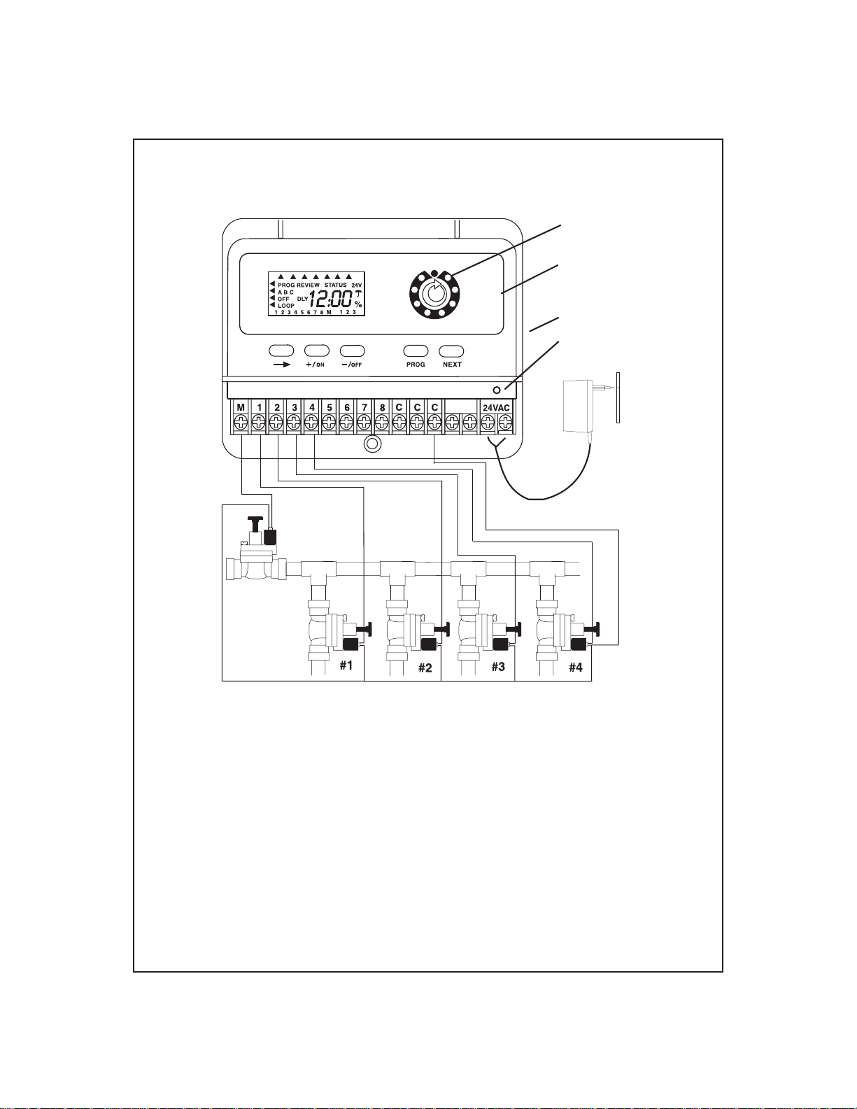
INSTALLATION INSTRUCTIONS - INDOOR MODELS:
Programming
guide light
Year
Month
Day
Time
Master
Valve
Su Mo Tu We Th Fr Sa
Station
Start
System off
Semi-Auto
Manual
% Scaling
AUTO
Set Time/Day
Run Times
Water Days
Start Time
RESET
SENSOR
LCD INLAY -
To place or replace
look at instruction
inside the plastic bag.
9 volt
battery drawer
Reset electronic fuse
TRANSFORMER
install in a
protected area.
common to all valves
Remove the lower cover. Place the unit on the wall using the top screw slot. Level
the controller, then insert screw into the lower screw hole under the terminal block.
Connect the solenoid wires to the terminal block. Connect one wire from the solenoid to
its respective station number on the terminal block and the other wire to the C-common
terminal. Connect the transformer wires to the 24 VAC terminal.
Note: A 9 VDC battery must be installed for proper operation of the controller. The 9
volt battery compartment is located on the right side of the case. It is marked “Push”. Push
it to release the battery drawer. The 9 volt battery powers the LCD display in the absence
of AC power and allows “Arm Chair Programming”. Program information is retained
during power outages by an on-board lithium battery.
NOTE: Only after all the wiring is completed and checked should the transformer be
plugged into AC power.
3
Page 4
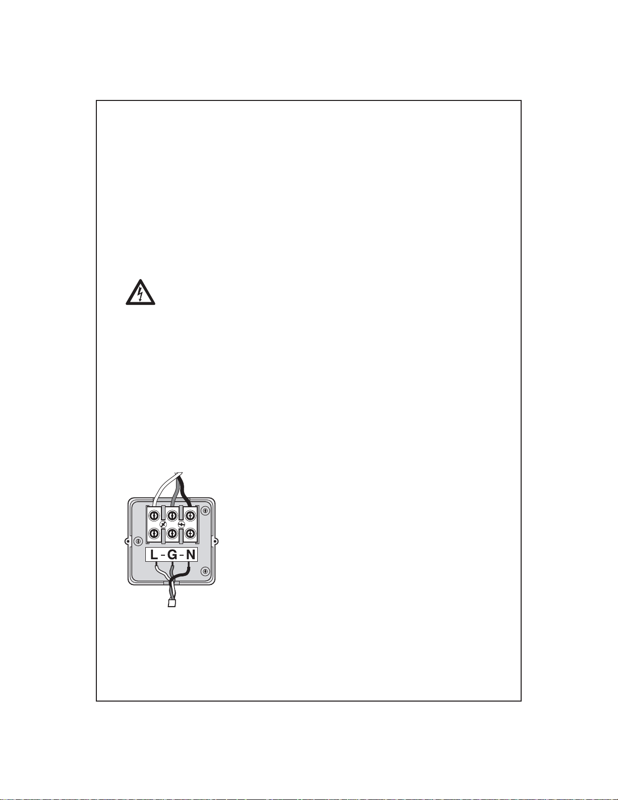
INSTALLATION INSTRUCTIONS - OUTDOOR MODELS:
Remove the lower cover of the Junior Max controller by sliding it down. Place the unit on
the wall using the top keyhole screw slot. Level the controller and then insert screws into
one or more of the three lower screws holes at the cabinet bottom. Drive the screws
through the plastic flashing that keep the cabinet weather resistant. If installing the
controller on drywall or masonry, install screw anchors to prevent the screws from
loosening. Connect the solenoid wires to the terminal block through the 12mm (1/2”) hole
in the right side of the cabinet bottom. If the solenoid wires are being installed in conduit,
there is a knock-out on this hole that will accept a 24mm (1”) male conduit adapter.
Connect the wires as shown for the indoor model. Next connect the power wires.
Warning: AC power wiring must be installed and connected by qualified
personnel only. All electrical components and installation procedures must comply with all
local and national electrical codes. Some codes may require a means of disconnection
from the AC power source installed in the fixed wiring and having a contact separation of
at least 3mm (0.120”) in the line and neutral poles.
Make sure the power is OFF prior to connecting the controller.
The hole on the left side of the cabinet bottom accepts a 12mm (1/2”) male conduit adapter.
Route the power and equipment ground wires from the power source, through the conduit
and into the transformer connector compartment. Note: The terminal block accepts wire
size up to 4mm2 (12 AWG). Remove 10mm (3/8”) of insulation from the wire ends.
Using a small flat bladed screwdriver, secure the wires as follows: Line or Line 1 (L1) to
L, Neutral or Line 2 (L2) to N and Equipment Ground to G. Install compartment cover.
Apply power to the controller.
9 VDC Battery. The 9 volt battery compartment is located below the 24VAC terminals.
The 9 volt battery powers the LCD display in the absence of AC power and allows
programming without AC power. Program information is retained during power outages
by an on-board lithium battery.
4
Page 5

Sensor connection and operation:
Manual
% Scaling
AUTO
Set Time/Day
Run Times
Water Days
Start Time
RESET
SENSOR
TRANSFORMER
install in a
protected area.
Su Mo Tu We Th Fr Sa
Year
Month
Day
Time
Station
System off
Semi-Auto
Start
SENSOR
To connect a rain sensor, remove the jumper wire from the sensor terminal and connect
one wire of the Irritrol Rain Sensor to the C-common terminal and the other wire to the
N.C. (normally closed) terminal. As soon as the Rain Sensor contacts change from the
N.C. position to the N.O. (normally open) position, irrigation will be suspended.
Irrigation will resume as soon as the Rain Sensor dries and its contacts return to the N.C.
position.
When irrigation is suspended due to the Rain Switch, the display shows: OFF
5
Page 6

PROGRAMMING:
It is recommended to press the RESET button to clear the memory.
Press NEXT to advance to SET TIME/DAY
Program Position: SET TIME/DAY
Set the current YEAR, MONTH, DAY & TIME.
Set the YEAR with +/ON or -/OFF
Press
Set the MONTH with +/ON or -/OFF
Press
Set the DAY with +/ON or -/OFF
Press
Set the TIME with +/ON or -/OFF
Press if you wish to go back to YEAR setting.
NOTE: If you press and hold either +/ON or -/OFF continuously, the digits
will advance quickly.
Press NEXT to advance to RUN TIME
Program Position: RUN TIME
This controller has 3 independent programs: A, B & C. Select the stations you wish to
have for each program. Program A is the first program.
You can assign stations to a program by entering RUN TIME for these stations.
Unselected stations in a program will remain OFF.
Press PROG to select the program to be set.
Press +/ON or -/OFF to set the desired RUN TIME.
Press to advance to next station.
To RESET Run Time back to "OFF": Press BOTH +/ON and -/OFF for a few seconds
until OFF is displayed.
To disable the MASTER VALVE from working in this program:
Press until "M" starts flashing. The display show "On".
Press -/OFF to disable the MASTER VALVE. Press +/ON to resume its operation.
Press NEXT to advance to WATER DAYS
6
Page 7

Program position: WATER DAYS
Calendar
Prog. A
Interval
Prog. A
day
Interval
start
Odd
Prog. A
There are 4 choices for your days selection:
CAL - Select days of the week. (Default all days are ON)
Int - Select days interval, 1-7 days, and the 1st day to start the interval
Odd - Irrigation on Odd days (31st day is skipped)
En - Irrigation on Even days.
In CAL position: Press +/ON for operating day or -/OFF to skip the day.
Press for Interval selection or NEXT for next programming step.
In "Int" position: Press +/ON or -/OFF to select your days interval.
Press to select the 1st day to start the watering using +/ON or -/OFF.
In Odd position: Press to select Even days.
NOTE: 31st day of month is skipped in ODD water days.
In Even position: Press if you wish to go back to CALENDAR.
Press NEXT to advance to START TIMES.
Even
Prog. A
Program position: START TIMES
3 start times per day are available for each program.
Press +/ON or -/OFF to set the first start time.
Press for start #2 and #3 and repeat with +/ON or -/OFF to set the time.
To RESET Start Time back to "OFF": Press BOTH +/ON and -/OFF for a few seconds
until OFF is displayed.
After setting start times, you can Press PROG to start entering data for the next program.
The program position will automatically move back to the RUN TIME position of the next
program.
If you press NEXT you advance to the “% Scaling” position.
7
Page 8

Program position: % SCALING (Seasonal adjust)
In this program position, you can increase or decrease the RUN TIMES of all stations in a
program by percentage scaling from 0% (program OFF) to 200% in 10% increments.
Press PROG to select the program you wish to % scale.
Press +/ON or -/OFF to change adjustment from 100%
The initial RUN TIME set represents 100%. Scaling increases or decreases this initial run
time. The new adjusted run time will be displayed whenever the program is operating.
The “%” icon will also be displayed whenever that program is operating or being
reviewed to alert you that the run time has been adjusted from the initial setting.
To set a program to "OFF"
If you wish to stop irrigation of a program, set percentage scaling to 0%.
The display will show that program is OFF.
To resume normal operation of that program, advance to "% SCALING" and increase the
percentage to your desired value. Increasing to 100% will set RUN TIME to its original
value.
Press PROG to select the program.
Press NEXT to advance to MANUAL.
Program position: MANUAL
In this MANUAL mode, you can set RUN TIME for each of the stations you wish to start
manually. Stations will start in sequence.
Press +/ON or -/OFF to set the station RUN TIME.
Press to advance to next station.
To turn ON the 1st station in the sequence:
Press NEXT to AUTO-RUN position.
Press -/OFF (in AUTO-RUN position) to turn OFF the sequence.
All stations with RUN TIME will be displayed. Operating stations will flash and the
display will show the remaining RUN TIME of the station (count down).
Press NEXT to advance to SEMI-AUTO.
8
Page 9

Program Position: SEMI-AUTO
In this dial position you can start a sequence of all stations programmed in the selected
program.
Press PROG to select the program you wish to operate.
Display shows all the stations programmed in the selected program
Press if you wish to select another station as the 1st station.
Press +/ON to turn ON the sequence.
Press to skip from a working station to the next one in the sequence.
Press -/OFF to turn OFF the sequence (before it is completed).
The display will show the remaining RUN TIME of each operating station.
Press NEXT to advance to SYSTEM OFF.
Program Position: SYSTEM OFF
OFF
All Prog.
Rain Delay
0-7 days
Press
Prog. Er.
Prog. A
Press
Prog. Er.
Prog. B
Press
Prog. Er.
Prog. C
3 main functions can be performed in this program position.
TURN ALL PROGRAMS OFF - Irrigation is suspended for all programs. It will
remain suspended as long as the programming
guide light stays in this position.
Press to set next function OR Press NEXT to advance to AUTO-RUN
RAIN DELAY: - Irrigation is delayed for the selected number of days.
Press +/ON or -/OFF to select the number of days.
The display will show the umbrella, DLY=DELAY and the day the irrigation will resume
(Flashing).
9
Page 10

Press to set next function OR Press
PROGRAM ERASE – You can erase all data entered into a program. Can be
done for a selected program.
Press to select the program you wish to erase.
Press +/ON to erase. PE will flash 5 times.
Press
to advance to AUTO-RUN.
NEXT
to advance to AUTO-RUN
NEXT
Program position: AUTO-RUN
AUTO
This position is used to provide information regarding the operation as well as for
reviewing all data stored in the irrigation programs.
Following is the list of information you can observe on the display:
• Current Time & Day
• A program(s) in OFF position
• Information regarding the operating station: program, station and remaining run time
• Active Rain Delay
• If irrigation is suspended due to SENSOR input
• Power failure indication
To turn OFF the working cycle, press NEXT to SEMI-AUTO and press -/OFF.
If you wish to review what data you have in each program:
Press to PROGRAM REVIEW. Press PROG to select the program.
Press +/ON to start the review.
If you wish to have a complete status report on the operating station:
Press to STATUS.
Program
Review
Status
Remaining station RUN TIME will be displayed as well as the operating program, station
number and active start time.
Press to return to AUTO-RUN position.
10
Page 11

Program C – Looping Program
Program C runs as a regular program if only one start time is used. Entering a second and
third start time changes program C to a looping program. The controller recognizes this
and displays “LOOP” in the LCD display.
A looping program allows the station assigned to program C to be run repeatedly
throughout a 24 hour period. A loop program is desirable for seed germination, asexual
propagation, misting and cooling. Sensors such as thermostats, humidity sensors, etc., can
be incorporated into the looping program.
NOTE: Important Differences
1. If only one start time is entered, the controller considers Program C as a regular
program and run times are set and displayed in hours and minutes.
2. When a second start time is entered, the controller recognizes that program C is being
set as a looping program. Run times are now set and displayed as minutes and seconds.
The second and third start times are still set and displayed in hours and minutes. As an
example, the third start time is the loop delay. You want a delay of 120 minutes. The
display will show 2:00 or two hours.
3. Loop delay includes the station Run Times
4. Loop delay default time is 5 minutes
Example: You are germinating a seed lawn and wish to irrigate every half-hour between
7:00 AM and 6:00 PM. Station run time is 2 minutes.
Run Time = 2:00 = 2 minutes
“Start 1” = 7:00 AM = Time the loop will start
“Start 2” = 6:00 PM = Time the loop will stop
“Start 3” = 0:30 = 30 minute loop delay
Watering time
Station 1
2 minutes
0700
Station 2
2 minutes
Loop Delay - 30 minutes
Station 3
2 minutes
From start to start
11
Watering time
Station 1
2 minutes
0730
Station 2
2 minutes
Station 3
2 minutes
Page 12

www.irritrol.com
Tel:
800-634-TURF (8873)
Fax:
800-862-8676
Junior MAX Custom Watering Plan
3 Program Controller
Date:
Station
1
2
3
4
5
6
7
Description
Duration Duration
Duration
(min. & sec.)
Program A Program B Program C
Program A Program B Program C
Irrigation Days Su Mo Tu We Th Fr Sa Su Mo Tu We Th Fr Sa Su Mo Tu We Th Fr Sa
Days Cycle
Start 1 Loop Start:
Start 2 Loop End:
:yaleD pooL3 tratS
Electromagnetic Compatibility
Domestic: This equipment generates and uses radio frequency energy and if not installed and used properly, that is, in strict accordance
with the manufacturer's instructions, may cause interference to radio and television reception. It has been type tested and found to
comply with the limits for a FCC Class B computing device in accordance with the specifications in Subpart J of Part 15 of FCC Rules,
which are designed to provide reasonable protection against such interference in a residential installation. However, there is no guarantee
that interference will not occur in a particular installation. If this equipment does cause interference to radio or television reception,
which can be determined by turning the equipment off and on, the user is encouraged to try to correct the interference by one or more of
the following measures:
• Reorient the receiving antenna.
• Relocate the irrigation controller with respect to the receiver.
• Move the irrigation controller away from the receiver.
• Plug the irrigation controller into a different outlet so that the irrigation controller and receiver are on different branch circuits.
If necessary, the user should consult the dealer or an experienced radio/television technician for additional suggestions. The user may
find the following booklet prepared by the Federal Communications Commission helpful:
"How to Identify and Resolve Radio-TV Interference Problems". This booklet is available from the U.S. Government Printing Office,
Washington, DC 20402. Stock No. 004-000-00345-4.
International: This is a CISPR 22 Class B product.
© 2008 Irritrol
 Loading...