

Page 1

446PR / 446PRI
IRRIGATION CONTROLLER
INSTALLATION AND OPERATING GUIDE
Page 2
FEATURES
SIX ZONE CONTROL: Turns up to six sprinkler valves on and off
automatically in sequence.
DUAL PROGRAMMING: Allows you to water your lawn and landscape
on separate schedules.
EASY AT-A-GLANCE SETTINGS: Makes it simple to set watering
lengths and days.
MULTIPLE START TIMES: Lets you water up to four times per day -
ideal for new lawns.
EXTENDED WATERING PERIODS: Allows you to water up to 99 min-
utes a day per zone.
PAUSE FUNCTION: Makes it easy to interrupt watering cycles for yard
activities.
MANUAL OPERATING MODE: Allows you to water manually when an
automatic watering cycle is not in progress.
ELECTRONIC CIRCUIT BREAKER: Prevents controller shut-down in
the case of a short circuit in a valve; diagnostic feature displays malfunctioning valve number for easy trouble-shooting.
MASTER VALVE/PUMP START CONNECTION: Automatically turns a
pump or a master valve on and off. (Requires a pump start relay, Model
SR-1, if used with a pump).
TO USE YOUR NEW CONTROLLER MOST EFFECTIVELY, PLEASE
READ THIS MANUAL CAREFULLY AND REFER TO THE MANUAL IF
ANY DIFFICUL TIES ARISE.
NOTE:
trical surges caused by unstable power supply, consult your local supplier
or contractor for additional protection devices which may be required.
For areas which are vulnerable to lightning strikes, or transient elec-
2
Page 3
TABLE OF CONTENTS
Controller Components . . . . . . . . . . . . . . . . . . . . . . . . . 4–5
Installation Procedures
• Selecting The Location . . . . . . . . . . . . . . . . . . . . . . . . . . . . 6
• Mounting The Controller . . . . . . . . . . . . . . . . . . . . . . . . . 6–7
• Connecting The Valve Wires . . . . . . . . . . . . . . . . . . . . . 7–8
• Connecting APump Start Relay Or Master Valve . . . . . . . . 8
• Connecting The Power Source (Outdoor Models) . . . . 9–10
• Connecting The Battery . . . . . . . . . . . . . . . . . . . . . . . . . . 10
Planning Your Watering Schedule
• Guidelines For Watering . . . . . . . . . . . . . . . . . . . . . . . . . . 11
• Selecting The Right Program . . . . . . . . . . . . . . . . . . . . . . 11
• Filling In The Watering Schedule Form . . . . . . . . . . . . . . . 11
• Watering Schedule Forms . . . . . . . . . . . . . . . . . . . . . . . . 12
Programming Steps
• Setting Correct Time . . . . . . . . . . . . . . . . . . . . . . . . . . . . . 13
• Assigning Zones To AProgram . . . . . . . . . . . . . . . . . . . . . 13
• Setting Program Start Times . . . . . . . . . . . . . . . . . . . . 14–15
• Setting Zone Run Time . . . . . . . . . . . . . . . . . . . . . . . . . . . 15
• Setting Program Cycle Days . . . . . . . . . . . . . . . . . . . . . . 15
Manual And Semi-Auto Operation
• Manual Operation . . . . . . . . . . . . . . . . . . . . . . . . . . . . . . . 16
• Semi-Auto Operation . . . . . . . . . . . . . . . . . . . . . . . . . . . . 16
Controller Shut-down / Circuit Breaker
• Controller Shut-Down . . . . . . . . . . . . . . . . . . . . . . . . . . . . 17
• Electronic Circuit Breaker . . . . . . . . . . . . . . . . . . . . . . . . . 17
Voltage Specifications . . . . . . . . . . . . . . . . . . . . . . . . . . . 18
Troubleshooting . . . . . . . . . . . . . . . . . . . . . . . . . . . . . . . . 18
Electro-Magnetic Compatibility . . . . . . . . . . . . . . . . . . . . 19
3
Page 4
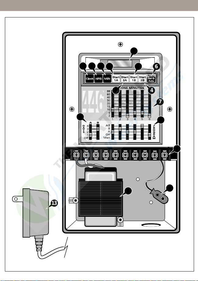
1
2
3
4
5
4
6
44
7
8
9
10
11
12
13
Figure 1
CONTROLLER COMPONENTS
4
Page 5
CONTROLLER COMPONENTS
CLOCK - DAY NOW KEY
1
Allows you to set the current time and day
2
HOURS KEY
Allows you to set the correct hour for the current time as well as the
hour for the desired start times.
MINUTES KEY
3
Allows you to set the correct minute for the current time as well as
the minute for the desired start times.
4
START KEYS
Enable you to set the start times of each programs (two start times
for program A and two for program B).
5
CONTROLLER DISPLAY
It displays the current time or the zone number being watered with its
watering run time when a program is in progress. It also indicates
programming errors and short circuits when detected.
6
PAUSE - SEMI-AUTO KEY
Temporarily interrupts a watering cycle in progress or allows you to
start a semi-automatic watering cycle
7
ZONE MINUTES SWITCHES
Allows you to select the watering time duration for each zone from
2–99 minutes
8
PROGRAM SWITCHES
Allows you to designate each zone to program (A, B, or AB).
9
DAYS SWITCHES
Allows you to set the day interval for each watering program.
TERMINAL SCREWS
10
Terminal connections for the power source, zone 1–6, pump
start/master valve and valve common.
11
BA TTERY CONNECTOR
Connects a 9 volt battery to retain stored watering cycle programs in
case of a power failure.
12
INTERNAL TRANSFORMER (Outdoor models)
Enables the controller to connect to a 120 V a.c., 60 Hz source
(220/240 V a.c., 50 Hz source for the international units).
13
PLUG-IN TRANSFORMER (Indoor Models)
Supplied with 120 V a.c., 60 Hz.
5
Page 6
INSTALLATION PROCEDURE
WARNING: All electrical components must meet applicable
national and local electrical codes including installation by
qualified personnel. These codes may require an external junction
box mounted on the transformer 1/2" nipple and a means, in the
fixed wiring, of disconnecting AC power having a contact separation of at least 0.120" (3 mm) in the line and neutral poles. Ensure
the AC power source is OFF prior to connecting to the controller.
The wire used for connection to the controller must have insulation
rated at 105° C minimum.
STEP 1 : Selecting The Location
For the 446 PRI (indoor models), choose an indoor location near a standard
120 V a.c. wall outlet. Install the controller in an area protected from weather, such as a garage, and within 5' (1.5 m) of a grounded electrical outlet.
The 446 PR (outdoor model) can be installed almost anywhere, but avoid
exposure to direct sun or irrigation spray. The controller must be powered
by a well grounded AC circuit.
CAUTION: Do not place the controller where temperatures may
exceed 60° Centigrade (140° Fahrenheit) or on a circuit controlled by a
switch or on the same circuit with a high power user (refrigerator, air conditioner, garage door opener, etc.). Malfunctions may result.
STEP 2 : Mounting 446 PR Controller (Outdoor Model)
1. Mount the hanger kit (1 hanger and 1 screw) on the top rear of the con-
troller.
2. Position the controller on the wall slightly below eye level. Mark the
mounting screw location at the top of the hanger’s keyhole slot.
3. Install a #8 mounting screw into the wall at the marked location leaving
the screw head about 1/4" (6 mm) out from the wall.
4. Remove the screw from the controller’s bottom panel. Pull the panel out
to access the two bottom screw holes.
5. Hang the controller on the mounting screw while making sure the screw
head is secured at the top of the keyhole slot. Install the two bottom
mounting screws, then tighten the top keyhole screw securely.
6. Replace the lower bottom to the controller.
6
Page 7

INSTALLATION PROCEDURE
Mounting 446 PRI Controller (Indoor Model)
1. Install a #8 mounting screw at eye
level on the wall, leaving the screw
head extended 1/4" (6 mm) out from
the wall.
2. Hang the controller on the mounting
screw. Make sure the screw head is
secured at the top of the keyhole slot.
See
Figure 2.
3. Install the lower mounting screws.
4. Replace the controller’s bottom panel.
STEP 3 : Connecting The Valve Wires
CAUTION:
The power transformer is protected by an electronic circuit
breaker. Do not connect a combination of valves requiring an inrush current
above 1 Amp at 24 V a.c. to one zone terminal.
1. Route valve control wires
between the valves and the
controller.
Note: An 18 AWG (0.75
mm) multi-wire cable is rec-
ommended. This cable is
24V
AC
123456
ZONES
P
C
U
O
M
M
P
M
Pump Start Relay or
Master Valve
insulated for direct burial
and color coded to simplify
installation.
2. Attach the white color-coded
wire to one of the wires from
each valve solenoid (either
Zone 3
solenoid wire can be used).
The white wire is designated
as the valve common wire.
Zone 2
(continued to the next page)
Zone 1
Figure 2
Figure 3
Wire
Connector
Grease Cap
7
Page 8

INSTALLATION PROCEDURE
3. Attach a separate color-coded wire to the remaining wire from each
valve solenoid. Make a note of the wire color used for each valve and
the watering zone it controls. You will need this information when connecting the valve wires to the controller.
4. Secure all wire splices using a twist-on wire connectors. To prevent cor-
rosion and possible short circuit, use a grease cap or similar waterproofing method to insulate each wire splice connection. See
on page 7.
5. Remove the controller’s bottom panel and route the valve cable into the
controller through the conduit opening at the base of the cabinet. Strip
back the wire insulation, about 1/2" (13 mm), from all cable wires to be
connected.
Note: The identification label for each of the terminal screws are located
at the backside of the controller’s bottom plastic panel.
6. Secure the valve common wire to the terminal labeled
the individual valve wires to the valve terminals labeled 1–6 in the order
you wish the valve zones to operate.
7. Replace the controller’s bottom panel and test each valve for proper
operation using the
connecting the AC power source.
STEP 4 : Connecting A Pump Start Relay Or Master Valve
When a pump relay is required to be operated by the controller, a compatible relay must be used. The relay coil will be connected to the PUMP termi-
nal. Refer to the Voltage Specification on page 19 of this Installation Guide
for power requirements. The relay contacts will be connected to the pump
start terminals and must be rated for use with that particular pump.
CAUTION: To prevent controller damage, ensure the relay’s current
draw does not exceed 1A. Do not connect the controller directly to the
pump starter. The pump start relay must be installed at least 5' (1.5 m)
away from the controller.
1. Route a twisted pair cable from the pump relay or the master valve into
the controller housing through the conduit opening.
2. Connect one of the wires to the
to the terminal labeled PUMP.
3. Test for proper operation after connecting the AC power source.
MAN option under the PROGRAM switches after
COMM terminal and the remaining wire
Figure 3 insert
COMM. Connect
8
Page 9

INSTALLATION PROCEDURE
STEP 5 : Connecting The Power Source
The outdoor controller model has a built-in transformer which must be connected to a grounded AC power source. Refer to the POWER SPECIFICA-
TIONS on page 18 for the proper power requirements. Electrical conduit
and adapters are not supplied with the controller but are generally required.
Check local building codes and install conduit accordingly.
CAUTION: Before wiring the internal transformer, switch off power at
the source. Do not link two or more controllers via a common transformer or
common wire.
PR (Outdoor Model)
1. Verify that the power has been turned
off at the power source by using an
appropriate AC voltage meter.
2. For the power wire connection, install
a 3/4" (19 mm) NPT threaded conduit
to the transformer assembly nipple.
Install electrical conduit from the con-
duit body to the AC power source cir-
cuit breaker panel.
Note: Figure 4 applies to 120 V a.c.,
60 Hz models only. For international
models, connect in accordance to
local and national electrical codes.
3. Route a three wire cable through the conduit and out from the conduit
body .
4. Splice the mating wires. Connect and insulate the wires with proper size
wire connectors. See
Figure 4.
5. Close and secure the conduit cover.
6. Apply power to the controller and test each valve for proper operation
using the
MAN option under the PROGRAM switches.
Figure 4
Neutral Line
White or Blue
Hot Line
Black or Brown
Conduit Body
Ground Line
Green or
Green/Yellow
9
Page 10

INSTALLATION PROCEDURE
PRI (Indoor Model)
Note:
The plug-in transformer is supplied with the 120 V a.c., 60 Hz indoor
controller models only. See page 18 for the controller’s proper power specifications.
CAUTION: Make sure the transformer is unplugged during installation.
1. Lift out the the controller’s bottom plastic panel.
2. Route the plug-in transformer cable into the controller through the pro-
vided conduit opening at the base of the cabinet.
3. Attach the transformer cable to the 24 V a.c. terminals. Make sure the
transformer leads do not make contact.
4. Replace the bottom panel of the controller.
5. Plug in the transformer to apply power to the controller and test each
valve for proper operation using the
switches.
STEP 6 : Connecting The Battery
1. Remove the bottom panel of the controller.
2. Connect a 9 volt alkaline battery (not supplied) to the battery connector
found inside the wiring compartment. Installing a battery enables the
controller to retain watering programs stored in the controller’s memory
during power failures. See
3. Replace the bottom panel.
CAUTION: Batteries contain hazardous materials. Always handle and
discard batteries properly in accordance with the battery manufacturer’s
recommendations.
Figure 2 on page 7.
MAN option under the PROGRAM
10
Page 11

PLANNING YOUR WATERING SCHEDULE
Guidelines For Watering
There are several factors to be considered when deciding when and how
long to water. For example, the soil type (i.e. clay, loam, etc.), the part of the
landscape being watered, climate conditions and the type of sprinklers
being used. Because of these variables, we cannot provide an exact schedule to follow, but here are some general watering guidelines to help you get
started.
• Water early in the morning, one to two hours before sunrise. You will
have the best water pressure at this time and the water can soak into
the plant root zone while evaporation is minimal. Watering during midday or in the evening may cause plant damage or mildew.
• For new lawns where frequent watering is required, take advantage of
the multiple start time feature of the 446 PR/PRI controller. Each
watering program cycle can be initiated twice a day.
• If under- or over-watering signs are observed, adjust program immedi-
ately .
Select The Right Program
On the following pages are some guidelines for planning your automatic
watering programs. We recommend taking a few moments to review this
information and filling in the watering schedule form provided.
Filling In The Watering Schedule Form
It is always helpful to plan your watering schedule on paper before beginning the programming steps. When completed, you will have a guide to use
during programming, and a record of your watering schedule which can be
kept with the controller for future reference.
Here are the information you will need to program your controller for automatic operation:
•
Location - Identify the location of each valve’s watering zone number.
•
Zone Run Time - Indicate the amount of watering run time required for
each zone (2–99 minutes).
•
Watering day schedule
Identify the watering day schedule for each program (everyday, every
other day, every third day or every fourth day interval).
•
Program Start Times Indicate the time of day you wish each watering
program to start.
11
Page 12

WATERING SCHEDULE FORMS
1
2
3
4
5
6
STATION
STATION RUN TIME
STATION RUN TIME
1
2
1
2
LOCATION
WATERING
DAY SCHEDULE
2nd
Every 2nd,
3rd or 4th Day
Everyday Off
3rd
PROGRAM
START TIMES
PROGRAM AWatering Schedule Form
PROGRAM B
4th
2nd
3rd
4th
Everyday Off
1
2
3
4
5
6
STATION
STATION RUN TIME
STATION RUN TIME
1
2
1
2
LOCATION
WATERING
DAY SCHEDULE
2nd
Every 2nd,
3rd or 4th Day
Everyday Off
3rd
PROGRAM
START TIMES
PROGRAM AWatering Schedule Form
PROGRAM B
4th
2nd
3rd
4th
Everyday Off
12
Page 13

PROGRAMMING STEPS
STEP 1 : Setting The Correct Time
The controller’s clock features a 12-hour format where 1200P represents
12:00 p.m. (noon) and 1200A represents 12:00 a.m. (midnight). When
power is first applied, the controller automatically resets the day and time to
Day 1 and 400P.
1. Press the
2. Advance the hour digit by holding down or by pressing the
repeatedly until the correct hour and A (a.m.) or P (p.m.) is displayed.
3. Advance the minute digit by holding down or by pressing the
repeatedly until the current minute is displayed.
4. Once the current time is set, the procedure is completed. If no additional
key is pressed within 15 seconds, the controller will revert back to time
mode.
STEP 2 : Assigning Zones To AProgram
The controller provides several options that allow simple, flexible programming. The dual program feature provides the ability to water individual
areas of the yard on separate schedules.
A typical example of how these programs might be used would be to assign
all lawn zones to program
watering demands are generally quite different for lawns and shrubs, dual
programming enables watering days and start times to be tailored specifically for each type of plant material.
1. Select each zone’s watering program by simply moving each zone’s
program switch to
bination of program A and B.
2. To disable a zone, simply move its designated zone switch into the
position.
Note: If a zone switch is placed in the AB position, the zone will start watering at every start time programmed in both A and B. Unused zones should
be placed in the OFF position.
Clock key to place the controller in time setting mode.
HRS key
MIN key
A and all shrub zones to program B. Since
A for program A, B for program B or AB for the com-
OFF
13
Page 14

PROGRAMMING STEPS
STEP 3 : Setting Program Start Times
A program start time is the designated time when the programmed automatic watering cycle begins. Sometimes it is necessary to run a program more
than once within the same day, for example, when growing a new lawn.
The controller has the ability to start each program twice a day.
Refer to the following guidelines when programming the start times:
• A start time (
individual zone.
• A program requires only one start time to operate automatically.
• When a program starts, each zone assigned to the program will water
in numerical order,
• Enough time should be provided between program start times to allow
all zones assigned to the program to be watered. If a start time produces a watering cycle that runs beyond the next start time, the controller will delay the next start time(s) to allow completion of the previous watering cycle.
• If a start time produces a watering cycle that runs past midnight, any
remaining start times scheduled to start before midnight will be cancelled.
• Start times begin according to the time they are programmed to water,
and not by the order at which they were programmed. For example,
the first start time programmed on
watering time to occur if it is programmed to water at 11:00 p.m., and
the last start time programmed on ST ART A may actually be the first
to occur if programmed to water at 5:00 a.m.
To Set Start Time
1. Press START 1A key. The display will show the current start time programmed in START 1A or OFF if it has been disabled.
2. Hold down or repeatedly press the
hour until the desired hour and A (a.m.) or P (p.m.) are displayed.
3. Hold down or repeatedly press the
the desired minute is displayed.
4. Repeat the process to program the other
5. To disable a start time, advance the start time hour until
played. OFF comes after 1100P.
6. Press the
NOTE: Once you have pressed a START key, you must press the HRS or
MIN key within 10 seconds. Otherwise, the controller will revert back to time
mode
14
ST ART A or START B) activates a watering cycle, not an
one at a time until its designated run time.
ST ART A may actually be the last
HRS key to advance the start time
MIN key to advance the minute until
ST ART times as needed.
OFF is dis-
Clock key to return the controller back to time mode.
Page 15

PROGRAMMING STEPS
STEP 4 : Setting The Zone Run Time
The zone run time is the duration the zone will water during a watering
cycle. Each of the six zones can be set to run at different duration between
2–99 minutes.
1. To set each zone’s run time, simply align each
the desired run time along the time indicator. Do not place the switch
between the indicated run times. During watering, the zone number and
its current run time will appear on the display
IMPORT ANT: Make sure the switches are placed on the minute marks and
not between the marks. Improper run time may occur.
STEP 5 : Setting Program Cycle Days
The DAYS switch sets the day interval for the program to cycle.
1. Move the
ing interval. Slide the switch to 4 for every 4th day, 3 for every 3rd day, 2
for every other day or 1 for everyday.
For example, if the
water every fourth day. After the switch is moved to 4, the display shows
day 1, which indicates a watering day. This means that program A will
water today if the watering time has not been missed.
By pressing the
day 1 to one of the following options:
day 0 - No more watering today.
day 1 - Water today.
day 2 - Water tomorrow.
day 3 - Water the day after tomorrow
day 4 - Water on the 4th day.
This option can be used when both programs are set to the same watering
cycle interval so program
To return the controller into time mode, press the
onds after the last keystroke.
2. Move the switch to
Note: The controller counts down from the day interval set to the designated active watering day. Day changeover occurs at 1200P.
DAYS switch for each program (A or B) to the desired water-
DAYS switch on program A is set to 4, the controller will
HRS key while the display shows day 1, you can change
A will water on a different day than program B.
OFF if a program is unused.
ZONE MINUTE switch to
Clock key or wait 10 sec-
15
Page 16

MANUAL AND SEMI-AUTO OPERATION
Step 1 : Manual Operation
1. To water your yard manually, move the PROGRAM switch of the zone
you wish to water to MAN. The controller will allow only one zone at any
given time to be watered manually. If more than one zone switch is
placed in the MAN position, only the lowest zone number will water.
When the switch is moved off the MAN position, the second lowest
zone number set to MAN will start to water. The MAN setting will override any automatic watering cycle including any watering cycle in
progress.
NOTE: When a zone switch is placed in MAN, the controller will water
continuously until the switch is moved.
Step 2 : Semi-Auto Operation
1. Semi-auto operation can be initiated by pressing the PAUSE - SEMI-
AUTO key. The controller will energize all the zones, one zone at a
time, starting from zone 1 until zone 6. The controller will skip any zones
that are disabled (zones placed in the OFF position within the PROGRAM switches). The zones will continue to water until their designated
time duration expires, then the next zone in sequence will start. The
controller will revert back to the time mode after watering the last zone
in the sequence.
2. Pressing the
sequence.
To pause the cycle, press the
play will alternately flash “P AUSE” as well as the station number and
run time. To resume the watering cycle, press PAUSE - SEMI-AUTO
key again and the station run time countdown will continue.
3. To exit the semi-auto operation, first pause the operation by pressing
the
PAUSE - SEMI-AUTO key. After pausing the semi-auto operation,
press the CLOCK key followed by the PAUSE - SEMI-AUTO key to ter-
minate the operation. When terminated successfully, OFF will be displayed. Pressing the MIN key repeatedly until the time mode is displayed will also exit the semi-auto operation.
Min key will advance the watering to the next zone in
PAUSE - SEMI-AUTO key once. The dis-
16
Page 17

CONTROLLER SHUT-DOWN / CIRCUIT BREAKER
Controller Shut-Down
When automatic watering is not needed, you can prevent the programmed
watering cycles from starting by moving the DAYS switches into the OFF
position.
NOTE: Manual watering is still possible even when the DAYS switches are
in the OFF position.
Electronic Circuit Breaker
The 446 PR/PRI controller is equipped with an electronic circuit breaker that
can detect short circuits in the valve zone terminals. If the controller detects
a short circuit, the shorted valve will automatically turn off. The display will
then alternately flash FUS with the shorted zone number. The controller will
continue to automatically water the remaining zones in the current watering
cycle as well as execute the next watering cycles.
After repairing the short circuit, press the
keys to return the controller to its current operating mode.
CLOCK or any of the START
17
Page 18

VOLTAGE SPECIFICATION / TROUBLESHOOTING
Voltage Specifications
Power Input Station Output Pump Output
Domestic Models
International Models 250 V a.c., 50 Hz., 18W 24 V a.c., 1 VA 24 V a.c., 9 VAmax.
Troubleshooting
120 V a.c., 60 Hz., 35W 24 V a.c., 1 VA 24 V a.c., 9 VAmax.
Problem
One or more valves do not
operate.
Display is stuck on a zone
FUS is flashing on the
and
display.
Continuous loss of time.
Zones turn on when they are
NOT programmed to start.
The clock has the correct
time and the zones appear to
be functioning properly, but
none of the valves are on.
Zone does not shut
OFF.
Possible Cause
1. Faulty solenoid.
2. Poor wire connection.
3. Possible break in wire.
4. Valve flow stem is screwed down too far.
1. Faulty solenoid.
2. Shorted or poor wire connection.
1. No battery.
2. Weak or bad battery.
3. Controller is on an electrical circuit controlled by a switch.
4. Controller is on the same circuit as a
high power user (refrigerator, air conditioner, etc.).
1. Start times and the total combined zone
run times have overlapped.
1. One or more zone switches are in the
OFF position.
2. The common wire is not hooked up.
3. Valve flow stem is screwed down too far.
1. Zone switch is in
2. Faulty valve.
3. Particles of dirt or debris are preventing
proper valve operation.
MAN.
18
Page 19

ELECTROMAGNETIC COMPATIBILITY
Domestic: This equipment has been tested and found to comply with the
limits for a Class B digital device, pursuant to Part 15 of the FCC Rules.
These limits are designed to provide reasonable protection against harmful
interference in a residential installation. This equipment generates, uses
and can radiate radio frequency energy and, if not installed and used in
accordance with the instructions, may cause harmful interference to radio
communications. However, there is no guarantee that interference will not
occur in a particular installation. If this equipment does harmful interference
to radio or television reception, which can be determined by turning the
equipment off and on, the user is encouraged to try to correct the interference by one or more of the following measures:
1. Reorient or relocate the receiving antenna.
2. Increase the separation between the equipment and receiver.
3. Connect the equipment into an outlet on a circuit different from that to
which the receiver is connected.
4. Consult the dealer or an experienced radio/TV technician for help.
The user may find the following booklet prepared by the Federal Communications Commission helpful:
“How To Identify and Resolve Radio-TV Interference Problems”. This book-
let is available from the U.S. Government Printing Office, Washington, DC
20402. Stock No. 004-000-00345-4.
International: This is a CISPR 22 Class B product.
19
Page 20

Irritrol Systems offers an entire family of products
for commercial and residential applications:
Controllers and Controller Accessories
Valves and Valve Accessories
Rotors, Spray heads, and Nozzles
U.S.A.:
P.O. Box 489
Riverside, California 92502
Tel: (909) 785-3623
(800) 634-8873
Europa:
Irritrol Systems Europe s.p.a.
Via dell’Artigianato, 1/3-Loc Prato della Corta
00065 Fiano Romano (Roma), Italia
Tel: (39) 0765 455201
© 2001 Irritrol Systems Form No. 373-0154 Rev. A
Australia:
Irritrol Systems PTY Ltd.
53 Howards Road
Beverley SA 5009
Tel: (08) 8300 3633
 Loading...