

Ironman Fitness 120r User Manual
Owner’s Manual
IRONMAN 120r RECUMBENT
Customer Service
1.800.750.IRON
1.800.750.4766
Ironman Fitness
4009 Distribution Drive
Suite 250
Garland, TX 75041
120r
www.ironmanfitness.com
315-00049
07/05 Rev A

Table of Contents
Important Safety Information 3
Before You Start 4
Assembly 5-8
Console Instructions 9
Moving Instructions 10
Monitoring Your Heart Rate 11-12
Warm Up Exercises 13
Exploded View 14
Parts List 15
Warranty 16
2

Important Safety Information
WARNING! Before using this unit or starting any exercise program, consult your physician. This is especially
important for persons over the age of 35 and/or persons with pre-existing health problems. The manufacturer
or distributor assumes no responsibility for personal injury or property damage sustained by or through the use
of this product.
WARNING! To reduce the risk of electrical shock, burns, fire, or other possible injuries to the user, it is
important to review this manual and the following precautions before operation.
SAFETY PRECAUTIONS AND TIPS
1. It is the owner's responsibility to ensure that all users of this unit have read the Owner's Manual and are
familiar with warnings and safety precautions.
2. This unit has a user maximum capacity of 250 pounds.
3. The unit should only be used on a level surface and is intended for indoor use only. The unit should not be
placed in a garage, patio. Ironman Fitness recommends a mat be placed under the unit to protect floor or carpet and for easier cleaning.
4. Wear comfortable, good-quality walking or running shoes and appropriate clothing. Do not use the unit with
bare feet, sandals, socks or stockings.
5. Always examine your unit before using to ensure all parts are in working order.
6. Allow the unit to fully stop before dismounting.
7. Pets should never be allowed near the unit.
8. Do not leave children unsupervised near or on the unit.
9. Never operate the unit where oxygen is being administered, or where aerosol products are being used.
10. For safety and to prevent damage to your unit, no more than one person should use the unit at a time.
11. Service to your unit should only be performed by an authorized service representative, unless authorized
and/or instructed by the manufacturer.
12. Failure to follow these instructions will void the unit warranty.
3
Before You Start
Thank you for purchasing the Ironman 120r Recumbent ! This quality product you have chosen was
designed to meet your needs for cardiovascular exercise. Before you start, please read the Owner's Manual and
become familiar with the operation of your new unit.
Remember to take the time to perform the stretching exercises provided to avoid injury.
If you are taking medication, consult your physician to see if the medication will affect your exercise heart
rate.
If you have heart problems, you are not active, and/or are over the age of 35 years, do not use the pre-set pro-
grams or start an exercise program without first contacting and receiving approval from your physician.
Do not spill liquids on the console. Ironman Fitness recommends a sealed water bottle for beverages consumed
while using the unit.
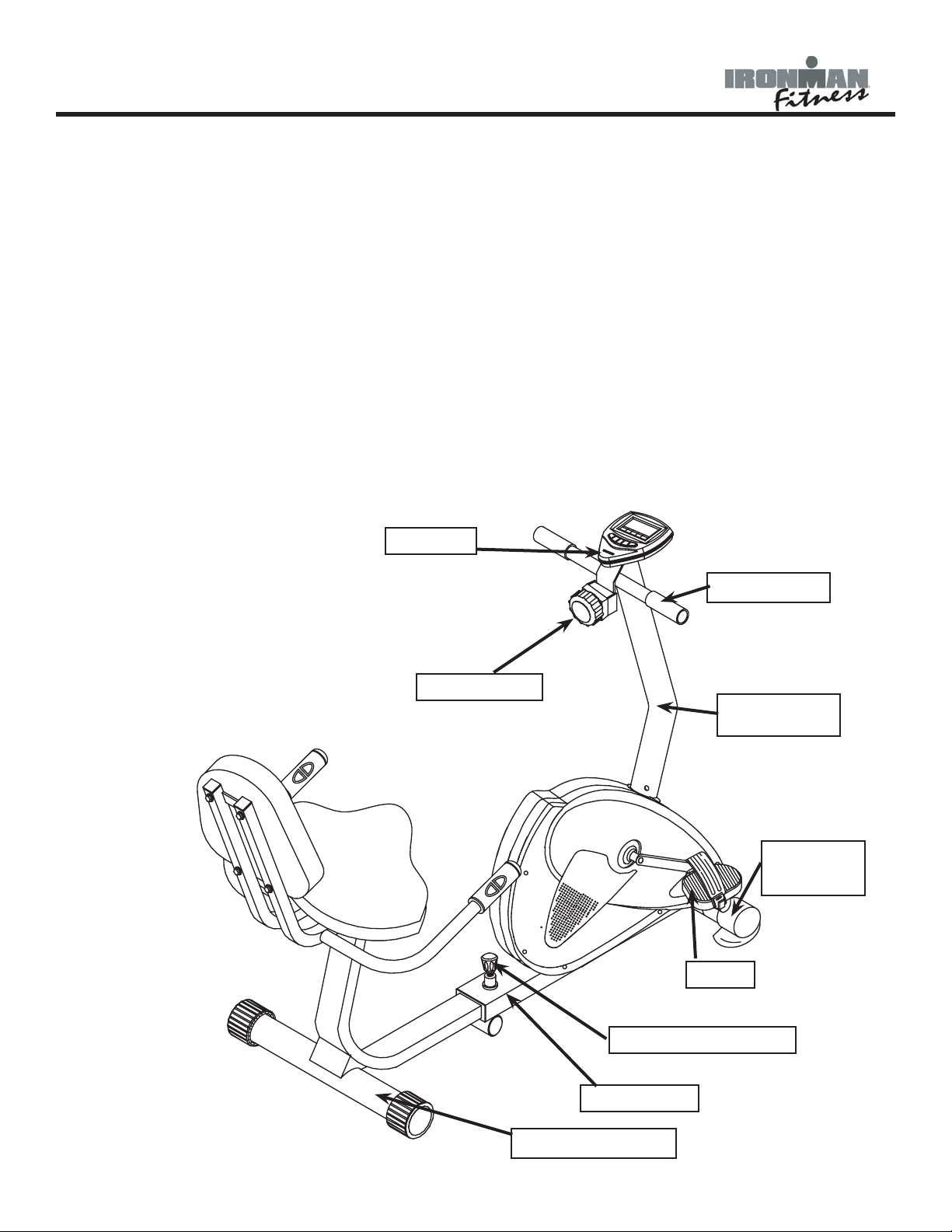
Please review the following drawing below to familiarize yourself with the listed parts.
CONSOLE
TENSION KNOB
HANDLEBARS
HANDLEBAR
POST
FRONT
STABILIZER
PEDAL
ADJUSTMENT KNOB
MAIN FRAME
REAR STABILIZER
4

Assembly
INSTRUCTIONS FOR ASSEMBLY:
Unpack the box in a clear area. Check to make sure all components are present and in good condition.
Do not dispose of the packing material until the assembly is completed. Tools have been provided for you
to use when assembling this product.
Locate the hardware pack and identify the following parts required for assembly.
Tools:
1. ALLEN WRENCH, M5 AND M6
2. PHILLIPS SCREW DRIVER
3. WRENCH
Main Components:
1. OWNER’S MANUAL
2. MAIN FRAME
3. FRONT STABILIZER ASSEMBLY
4. HANDLEBAR W/PULSE ASSEMBLY
6. HANDLE BAR POST
7. TENSION KNOB
10. CONSOLE ASSEMBLY
11. REAR STABILIZER ASSEMBLY
12. PEDALS LEFT AND RIGHT
Hardware:
1. SCREW M8X1 (49) - Qty 8
2. WASHER (63) - Qty 9
3. CARRIAGE SCREW M8X70 (35) - Qty 2
4. NUT M8 (37) - Qty 2
5. ARC WASHER (36) - Qty 6
6. CARRIAGE SCREW M8X40 (48) - Qty 4
7. NYLOCK NUT M8 (60) - Qty 6
8. HEX HEAD SCREW M6X40 (50) - Qty 8
9. WASHER (62) - Qty 8
10. SCREW M8X15 (49) - Qty 8
11. SCREW M5X10 (65) - Qty 1
5
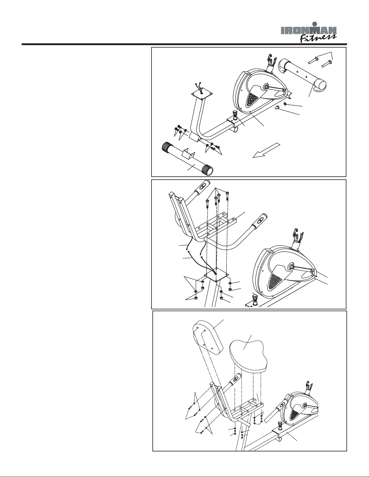
Assembly
FIGURE 1
Step 1:
Loosen the adjustment knob (41) on
the front frame (1). Slide the rear frame
backward and secure with the adjustment knob (41).
Step 2:
Attach the rear stabilizer (3) onto the
rear frame with screws (49) and washers
(63).
Step 3:
Attach the front stabilizer (34) onto the
main frame with carriage bolts (35), cap
nuts (37) and washers (36).
FIGURE 2
Step 1:
Connect Cables (76) to Cables (42).
Step 2:
Attach the seat frame (4) onto the rear
frame with carriage bolts (48), nylon
lock nuts (60) and washers (63).
Note: Be careful not to pinch cables.
FIGURE 3
Step 1:
Attach the seat (5) onto the seat frame
(4) with bolts (50) and washers (62).
Step 2:
Attach the back cushion (6) onto the
seat frame (4) with bolts (50) and washers (62).
Figure 1
49
63
Figure 2
42
76
63
Figure 3
60
35
34
36
37
41
63
3
49
48
63
60
63
60
6
1
4
41
5
50
4
62
50
50
62
50
62
50
1
6
 Loading...