

Ipso BA4121 Top-Load Parts Diagram
Automatic
W162S
Washers
Refer to Page 6 for Model Numbers
Service
www.alliancelaundry.com
Part No. 32305R2
November 2016


Table of Contents
Section 1 – Safety Information
Locating an Authorized Servicer ............................4
Section 2 – Introduction
Customer Service ....................................................5
Nameplate Location ................................................5
Model Identification ................................................6
Section 3 – Troubleshooting
1. No Hot Water ...................................................7
2. No Cold Water .................................................7
3. No Warm Water ...............................................8
4. Water Fill Does Not Stop At Proper Level ......8
5. Timer Does Not Advance (Mechanical Timer
Models only) ....................................................8
6. No Agitation .....................................................9
7. Constant Agitation ...........................................9
8. Slow Spin Or No Spin ....................................10
9. Constant Spin .................................................10
10. Drive Motor Overload Protector Cycles
Repeatedly ......................................................10
11. Outer Tub Does Not Empty ...........................11
12. Excessive Vibration .......................................11
13. Water Leaking From Outer Tub ....................11
Section 4 – Grounding
14. Wall Receptacle Polarity Check ....................13
15. Power Cord to Cabinet Top, Cabinet Top to
Control Hood Mounting Bracket, Pressure
Switch Mounting Bracket and Ground Tab
on Graphic Panel (Models BA4121, BA4120
and BA3110) ..................................................13
16. Power Cord to Control Hood (Models
BA2411, BA2410 and BA2300) ....................14
17. Control Hood to Bottom Flange of Control
Panel (Models BA2411, BA2410 and
BA2300) .........................................................14
18. Main Wire Harness to Top Rear Corner
Gusset of Cabinet ...........................................15
19. Motor to Mounting Bracket to Base ..............15
Section 5 – Service Procedures
20. Control Hood Assembly (Models BA4121,
BA4120 and BA3110) ...................................17
To Remove Control Hood End Caps..............17
21. Control Panel (Models BA2411, BA2410
and BA2300) ..................................................18
22. Timer (Models BA4121, BA4120 and
BA3110) .........................................................19
23. Timer (Models BA2411, BA2410 and
BA2300) .........................................................20
24. Temperature Switch or Speed (Action)
Switch ............................................................20
25. Pressure Switch ..............................................20
26. Graphic Panel (Models BA4121, BA4120
and BA3110) ..................................................21
27. Loading Door .................................................21
28. Agitator (Short Post Models) .........................22
29. Agitator, Drive Bell And Seal Seat Assembly
(Short Post Models) .......................................22
To Reinstall Drive Bell...................................24
30. Agitator Post Assembly (Long Post
Models) ..........................................................24
31. Agitator Drive Shaft (Long Post Models) ......26
32. Front Panel .....................................................26
33. Pump Belt ......................................................26
34. Drive Belt ................................................ .......27
To Install No. 28808 Drive Belt.....................27
35. Motor And Mounting Bracket .......................29
36. Idler Lever And Pulley ..................................29
37. Motor Drive Pulley ........................................31
38. Motor Switch .................................................31
39. Pump Assembly .............................................31
40. Cabinet Top Assembly ...................................32
To Remove Cabinet Top From Washer..........32
41. Door And Out-of-balance Switch And
Bracket Assembly ................................... .......33
42. Mixing Valve Assembly ................................34
43. Washtub And Lint Filter ................................ 34
Short Post Models...........................................34
To Remove Lint Filter From Washtub............36
To Install Lint Filter In Washtub .................... 36
Long Post Models...........................................36
44. Water Seal and Hub Assembly ......................37
Short Post Models...........................................37
To Install No. 495P3 Hub and Seal Kit ..........38
To Install Drive Bell and No. 39508P Seal
Kit ...................................................................40
45. Water Seal Assembly .....................................41
Long Post Models...........................................41
To Install No. 356P3 Washer Seal Kit............41
46. Outer Tub .......................................................43
Short Post Models...........................................43
Long Post Models...........................................45
© Copyright 2016, Alliance Laundry Systems LLC
All rights reserved. No part of the contents of this book may be reproduced or transmitted in any form or by any means without
the expressed written consent of the publisher.
32305
© Copyright, Alliance Laundry Systems LLC – DO NOT COPY or TRANSMIT
1

47. Drive Pulley and Helix ...................................47
48. Brake Assembly .............................................50
49. Lower Bearing Housing .................................50
To Remove Bearing........................................52
50. Transmission Assembly .................................52
To Disassemble Transmission Assembly .......54
To Reassemble Transmission Assembly.........59
51. Balance Ring ..................................................60
52. Upper Bearing Assembly ...............................60
53. Snubber Pads ..................................................60
To Install No. 434P3 Snubber Pad Kit............60
Section 6 – Adjustments
54. Timer Knob Indicator ....................................65
55. Leveling Legs .................................................65
56. Pressure Switch ..............................................66
57. Belt (Agitate and Spin) ..................................66
58. Belt (Pump) ....................................................66
59. Out-of-Balance Switch Trigger ......................67
Section 7 – Test Procedures
60. To Check Continuity Through Motor
Harness and Motor .........................................69
61. To Check Continuity Through Base Harness,
Control Harness and Timer For Motor Start
Circuit .............................................................69
Section 8 – Cycle Sequence Charts
Timer No. 28918 Cycle Sequence
(Two Cycle)...........................................................71
Timer No. 31239 Cycle Sequence
(Three Cycle).........................................................72
Section 9 – Internal Wiring of Washer Motor
Switch
Section 10 – Wiring Diagrams
Models BA4121 and BA4120................................76
Model BA3110.......................................................77
Models BA2411 and BA2410................................78
Model BA2300.......................................................79
.....................................................................73
..........................75
2
© Copyright, Alliance Laundry Systems LLC – DO NOT COPY or TRANSMIT
32305
Section 1
• Failure to install, maintain and/or operate this product according to the manufacturer’s
instructions may result in conditions which can produce serious injury, death and/or
property damage.
• Do not repair or replace any part of the product or attempt any servicing unless specifically
recommended or published in this Service Manual and unless you understand and have the
skills to carry out the servicing.
• Whenever ground wires are removed during servicing, these grou nd wires must be
reconnected to ensure that the product is properly grounded and to reduce the risk of fire,
electric shock, serious injury or death.
W006R2
WARNING
Safety Information
Throughout this manual and on machine decals, you will find precautionary statements (“CAUTION,”
“WARNING,” and “DANGER”) followed by specific instruc tions. These precauti ons are intende d for the person al
safety of the operator, user, servicer and those maintaining the machine.
DANGER
Danger indicates the presence of a hazard that wi ll cause severe personal injury, death or substantial property
damage if the danger is ignored.
WARNING
Warning indicates the presence of a hazard that can cause severe personal injury, death or substantial property
damage if the warning is ignored.
CAUTION
Caution indicates the presence of a hazard that will or can cause minor personal injury or property damage if the
caution is ignored.
Additional precautionary statements (“IMPORTANT” and “NOTE”) are followed by specific instructions.
IMPORTANT
The word “IMPORTANT” is used to inform the reader of specific procedures where minor machine damage will
occur if the procedure is not followed.
NOTE
The word “NOTE” is used to communicate installation, operation, maintenance or servicing information that is
important but not hazard related.
In the interest of safety, some general precautions relating to the operation of this machine follow.
32305
© Copyright, Alliance Laundry Systems LLC – DO NOT COPY or TRANSMIT
3
Section 1 Safety Information
To reduce the risk of electric shock, fire, explosion, serious injury or death:
• Disconnect electric power to the washer before servicing.
• Never start the washer with any guards/panels removed.
• Whenever ground wires are removed during servicing, these grou nd wires must be
reconnected to ensure that the washer is properly grounded.
W003
WARNING
Repairs that are made to your products by unqualified persons can result in hazards due to
improper assembly or adjustments subjecting you or the inexperienced person making such
repairs to the risk of serious injury, electrical shock or death.
W007
WARNING
If you or an unqualified person perform service on your product, you must assume the
responsibility for any personal injury or property damage which may result. The manufacturer
will not be responsible for any injury or property damage arising from improper service and/or
service procedures.
W008
WARNING
NOTE: The WARNINGS and IMPORTANT INSTRUCTIONS appearing in this manual are not meant to
cover all possible conditions and situations that may occur. Common sense, caution and care must be
exercised when installing, maintaining or operating the washer.
Always contact your dealer, distributor, service age nt or the manufac turer about any pro blems or condit ions you do
not understand.
Locating an Authorized Servicer
Alliance Laundry Systems is not responsible for personal injury or property damage resulting from improper
service. Review all service information before beginning repairs.
Warranty service must be performed by an authorized technician, using authorized factory parts. If service is
required after the warranty expires, Alliance Laundry Systems also recommends contacting an authorized
technician and using authorized factory parts.
4
© Copyright, Alliance Laundry Systems LLC – DO NOT COPY or TRANSMIT
32305

Section 2
W162S
Nameplate
Introduction
Customer Service
If literature or replacement parts are required, contact
the source from whom the machine was purchased or
contact Alliance Laundry Systems at (920) 748-3950
for the name and address of the nearest authorized
parts distributor.
For technical assistance, call (920) 748-3121.
Nameplate Location
When calling or wri ting about your p rodu ct, be sure to
mention model and serial numbers. Model and serial
numbers are located on nameplate(s) as shown.
32305
© Copyright, Alliance Laundry Systems LLC – DO NOT COPY or TRANSMIT
5

Section 2 Introduction
Model Identification
Information in this manual is applicable to these washer models.
BA4121 BA2411
BA4120 BA2410
BA3110 BA2300
6
© Copyright, Alliance Laundry Systems LLC – DO NOT COPY or TRANSMIT
32305
To reduce the risk of electric shock, fire, explosion, serious injury or death:
• Disconnect electric power to the washer before servicing.
• Never start the washer with any guards/panels removed.
• Whenever ground wires are removed during servicing, these grou nd wires must be
reconnected to ensure that the washer is properly grounded.
W003
WARNING
Section 3
Troubleshooting
IMPORTANT: Refer to appropriate Wiring Diagram for aid in testing washer components.
1. NO HOT WATER
POSSIBLE CAUSE TO CORRECT
Hot water su pply faucet is closed. • Open faucet.
Water supply is cold. • Check water heater.
Kinked hot water inlet hose. • Straighten or replace hose.
Clogged mixing valve screen, or screen in outer end
of inlet hose nearest water supply faucet.
Inoperative hot water mixing valve solenoid. • Test solenoid and replace if inoperative.
Inoperative timer. • Test timer and replace if inoperative.
Inoperative temperature switch. • Test switch and replace if inoperative.
Inoperative pressure switch. • Test switch and replace if inoperative.
Clogged pressure hose. • Remove and clean or replace hose.
Broken, loose or incorrect wiring. • Refer to appropriate wiring diagram.
• Disconnect hot water inlet hose, and clean or replace
screen.
2. NO COLD WATER
POSSIBLE CAUSE TO CORRECT
Cold water supply faucet is closed. • Open faucet.
Kinked cold water inlet hose. • Straighten or replace hose.
Clogged mixing valve screen, or screen in outer end
of inlet hose nearest water supply faucet.
Inoperative cold water mixing valve solenoid. • Test solenoid and replace if inoperative.
Inoperative timer. • Test timer and replace if inoperative.
Inoperative temperature switch. • Test switch and replace if inoperative.
Inoperative pressure switch. • Test switch and replace if inoperative.
Clogged pressure hose. • Remove and clean or replace hose.
Broken, loose or incorrect wiring. • Refer to appropriate wiring diagram.
• Disconnect cold water inlet hose, and clean or replace
screen.
32305
© Copyright, Alliance Laundry Systems LLC – DO NOT COPY or TRANSMIT
7
Section 3 Troubleshooting
To reduce the risk of electric shock, fire, explosion, serious injury or death:
• Disconnect electric power to the washer before servicing.
• Never start the washer with any guards/panels removed.
• Whenever ground wires are removed during servicing, these grou nd wires must be
reconnected to ensure that the washer is properly grounded.
W003
WARNING
3. NO WARM WATER
POSSIBLE CAUSE TO CORRECT
No hot water. • Refer to Paragraph 1.
No cold water. • Refer to Paragraph 2.
4. WATER FILL DOES NOT STOP AT PROPER LEVEL
POSSIBLE CAUSE TO CORRECT
Inoperative pressure switch. • Test switch and replace if inoperative.
Air leak in pressure hose. • Replace hose.
Sediment on or under mixing valve diaphragm,
defective diaphragm, or armature binding in
• Disassemble and clean mixing valve. Replace
deteriorated or not easily cleaned components.
armature guide.
Broken, weak or missing mixing valve armature
• Disassemble valve and replace spring.
spring.
A siphoning action started in washer will cause
water to be siphoned from washer during cycle due
• Install No. 562P3 Siphon Break Kit. Provide an air gap
around drain hose and drain receptacle.
to end of drain hose being lower th an cabine t top of
washer. Drain hose fits tight in standpipe or drain.
Water in pressure hose. • Blow air through hose to remove water.
Broken, loose, shorted or incorrect wiring. • Refer to appropriate w iring diagram.
5. TIMER DOES NOT ADVANCE (Mechanical Timer Models only)
POSSIBLE CAUSE TO CORRECT
Timer is designed to pause during fill periods. • Allow completion of fill period.
Inoperative timer. • Test timer, and replace if inoperative.
Loading door is open. • Close loading door. Loading door MUST be closed any
time the washe r is to agitate or spin.
Washer will not fill. • Timer pauses until pressure switch is satisfied. Refer to
Paragraph 1 and 2.
Timer motor lead wire off timer terminal. • Refer to appropriate wiring diagram and reattach wire.
Broken, loose or incorrect wiring. • Refer to appropriate wiring diagram.
8
© Copyright, Alliance Laundry Systems LLC – DO NOT COPY or TRANSMIT
32305
Section 3 Troubleshooting
To reduce the risk of electric shock, fire, explosion, serious injury or death:
• Disconnect electric power to the washer before servicing.
• Never start the washer with any guards/panels removed.
• Whenever ground wires are removed during servicing, these grou nd wires must be
reconnected to ensure that the washer is properly grounded.
W003
WARNING
6. NO AGITATION
POSSIBLE CAUSE TO CORRECT
Inoperative timer. Timer is designed to pause
• Test timer and replace if inoperative.
(SOAK) during DELICATE cycle.
Inoperative motor. • Test motor and replace if inoperative.
Inoperative pressure switch. • Test switch and replace if inoperative.
Broken, loose or incorrect wiring. • Refer to appropriate wiring diagram.
Loose or broken drive belt. • Adjust or replace belt.
Inoperative transmission assembly. • Repair or replace transmission assembly.
Sheared motor pulley roll pin. • Remove drive motor and replace roll pin and any other
damaged parts.
Drive motor overload protector has cycled. • Refer to Paragraph 10.
Bind in pump. • Replace pump.
Loading door is open or door switch is inoperative. • Close door or test switch and replace if inoperative.
7. CONSTANT AGITATION
POSSIBLE CAUSE TO CORRECT
Inoperative timer. • Test timer and replace if inoperative.
Inoperative drive motor. • Test motor and replace if inoperative.
Shorted or incorrect wiring. • Refer to appropriate wiring diagram.
Inoperative transmission assembly. • Repair or replace transmission assembly.
32305
© Copyright, Alliance Laundry Systems LLC – DO NOT COPY or TRANSMIT
9
Section 3 Troubleshooting
To reduce the risk of electric shock, fire, explosion, serious injury or death:
• Disconnect electric power to the washer before servicing.
• Never start the washer with any guards/panels removed.
• Whenever ground wires are removed during servicing, these grou nd wires must be
reconnected to ensure that the washer is properly grounded.
W003
WARNING
8. SLOW SPIN OR NO SPIN
POSSIBLE CAUSE TO CORRECT
Inoperative timer. • Test timer and replace if inoperative.
On some model washers, the timer is programmed
• Use a different cycle.
for SLOW spin in the DELICATE CYCLE
regardless of the action switch setting.
Loading door is open or door safety switch is
inoperative.
• Close loading door, or test switch and replace if
inoperative.
Bind in water pump. • Replace pump.
Inoperative drive motor. • Test motor and replace if inoperative.
Loose or broken drive belt. • Adjust or replace spin belt.
Washer has gone out of balance. • Open loading door to reset out-of-balance switch.
Rearrange load in washtub.
No clearance or stuck brake pads. • Free sticky brake pads or replace pads.
Broken, loose or incorrect wiring. • Refer to appropriate wiring diagram.
Inoperative transmission assembly. • Repair or replace the transmission assembly.
9. CONSTANT SPIN
POSSIBLE CAUSE TO CORRECT
Inoperative timer. • Test timer and replace if inoperative.
Inoperative drive motor. • Test motor and replace if inoperative.
Excessive wear on brake pads, or missing brake
• Replace brake pads.
pads.
Shorted or incorrect wiring. • Refer to appropriate wiring diagram.
10. DRIVE MOTOR OVERLOAD PROTECTOR CYCLES REPEATEDLY
POSSIBLE CAUSE TO CORRECT
Excessive belt tension. • Adjust belts.
Inoperative motor overload protector. • Replace motor.
Bind in water pump. • Replace pump.
Bind in transmission. • Repair or replace transmission.
Brake pads binding. • Free binding pads, or replace pads.
Incorrect voltage. • Contact local utility company, or have a qualified
electrician check power supply.
10
© Copyright, Alliance Laundry Systems LLC – DO NOT COPY or TRANSMIT
32305
Section 3 Troubleshooting
To reduce the risk of electric shock, fire, explosion, serious injury or death:
• Disconnect electric power to the washer before servicing.
• Never start the washer with any guards/panels removed.
• Whenever ground wires are removed during servicing, these grou nd wires must be
reconnected to ensure that the washer is properly grounded.
W003
WARNING
11. OUTER TUB DOES NOT EMPTY
POSSIBLE CAUSE TO CORRECT
Kinked drain hose. • Straighten hose.
Inoperative water pump. • Replace pump.
Obstruction in outer tub outlet hose. • Remove obstruction.
Loose or broken pump belt. • Adjust or replace belt.
12. EXCESSIVE VIBRATION
POSSIBLE CAUSE TO CORRECT
Unbalanced load in tub. • Stop washer, redistribute load, then restart washer.
Broken, disconnected or centering spring(s) out of
adjustment.
• Connect or replace centering spring(s). Spring should be
located in center notch. Refer to Figure 60.
Washer is not properly leveled. • Adjust leveling legs.
Washer is installed on weak, “spongy” or built-up
floor.
• Relocate washer, or support floor to eliminate weak or
“spongy” condition.
Incorrect or loose cabinet screws. • Replace with correct screws or tighten.
Base damaged (washer was dropped). • Replace base assembly.
Balance ring not positioned properly on
• Refer to Paragraph 51.
transmission assembly.
13. WATER LEAKING FROM OUTER TUB
POSSIBLE CAUSE TO CORRECT
Leaking water seal in outer tub. • Replace hub and seal kit assembly, Paragraph 44.
Hole in outer tub. • Replace outer tub.
Pressure hose or accumulator leaking. • Replace pressure hose and/or accumulator.
Outer tub cover gasket leaking. • Replace gasket.
Tub-to-pump hose leaking at clamp. • Tighten clamp.
32305
© Copyright, Alliance Laundry Systems LLC – DO NOT COPY or TRANSMIT
11

Section 3 Troubleshooting
Notes
12
© Copyright, Alliance Laundry Systems LLC – DO NOT COPY or TRANSMIT
32305
To reduce the risk of electric shock, fire, explosion, serious injury or death:
• Disconnect electric power to the washer before servicing.
• Never start the washer with any guards/panels removed.
• Whenever ground wires are removed during servicing, these grou nd wires must be
reconnected to ensure that the washer is properly grounded.
W003
WARNING
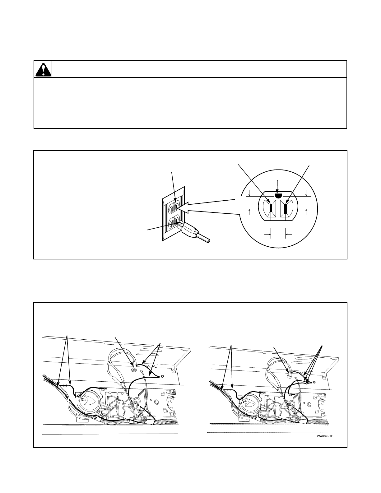
Section 4
W011G
NOTE: For determining
the correct polarity of a
wall receptacle.
Neutral
Ground
L1
Neutral
Side
Round
Grounding
Prong
0
VAC
115 ± 12
VAC
115 ± 12
VAC
Standard 120 Volt, 60 Hertz
3-Wire Effectively Grounded
Circuit
MECHANICAL TIMER MODELS
Power
Cord
Ground
Wires
(Some models)
Ground
Wires
Ground
Wires
Power
Cord
Ground
Wires
(Some models)
Grounding
14. WALL RECEPTACLE POLARITY CHECK
Figure 1
15. POWER CORD TO CABINET TOP, CABINET TOP TO CONTROL HOOD MOUNTING
BRACKET, PRESSURE SWITCH MOUNTING BRACKET AND GROUND TAB ON GRAPHIC
PANEL (Models BA4121, BA4120 and BA3110)
32305
© Copyright, Alliance Laundry Systems LLC – DO NOT COPY or TRANSMIT
Figure 2
13
Section 4 Grounding
To reduce the risk of electric shock, fire, explosion, serious injury or death:
• Disconnect electric power to the washer before servicing.
• Never start the washer with any guards/panels removed.
• Whenever ground wires are removed during servicing, these grou nd wires must be
reconnected to ensure that the washer is properly grounded.
W003
WARNING
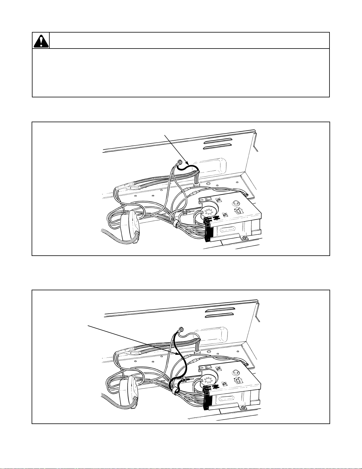
Ground
Wire
Ground
Wire
16. POWER CORD TO CONTROL HOOD (Models BA2411, BA2410 and BA2300)
Figure 3
17. CONTROL HOOD TO BOTTOM FLANGE OF CONTROL PANEL (Models BA2411, BA2410 and
BA2300)
14
© Copyright, Alliance Laundry Systems LLC – DO NOT COPY or TRANSMIT
Figure 4
32305
To reduce the risk of electric shock, fire, explosion, serious injury or death:
• Disconnect electric power to the washer before servicing.
• Never start the washer with any guards/panels removed.
• Whenever ground wires are removed during servicing, these grou nd wires must be
reconnected to ensure that the washer is properly grounded.
W003
WARNING
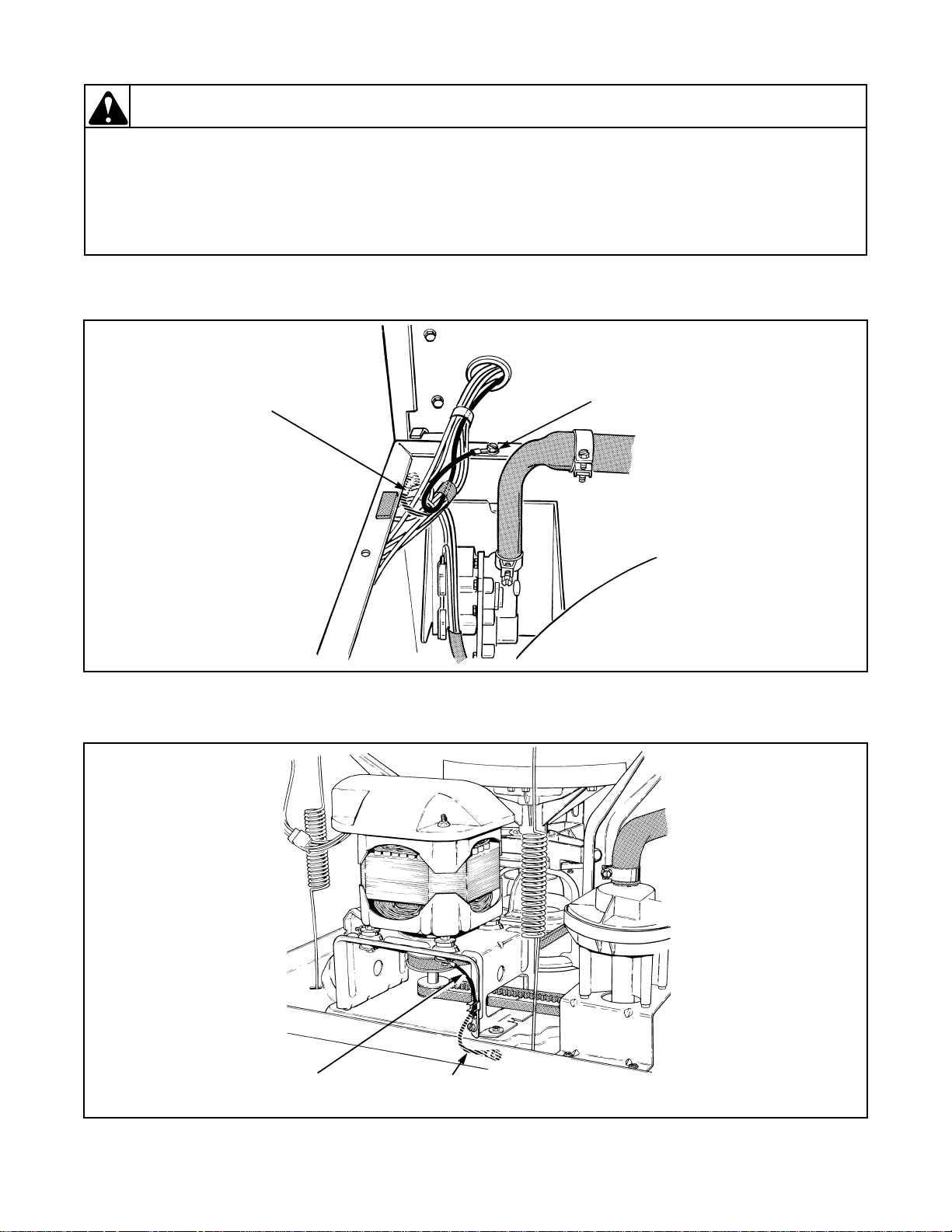
18. MAIN WIRE HARNESS TO TOP REAR CORNER GUSSET OF CABINET
Ground
Wire
on Cabinet
Corner
Gusset
(Some models)
Ground
Wire
on Cabinet
Flange
(Some models)
Ground
Wire
Ground Wire
(Some models)
Section 4 Grounding
Figure 5
19. MOTOR TO MOUNTING BRACKET TO BASE
32305
© Copyright, Alliance Laundry Systems LLC – DO NOT COPY or TRANSMIT
Figure 6
15

Section 4 Grounding
Notes
16
© Copyright, Alliance Laundry Systems LLC – DO NOT COPY or TRANSMIT
32305
To reduce the risk of electric shock, fire, explosion, serious injury or death:
• Disconnect electric power to the washer before servicing.
• Never start the washer with any guards/panels removed.
• Whenever ground wires are removed during servicing, these grou nd wires must be
reconnected to ensure that the washer is properly grounded.
W003
WARNING
Section 5
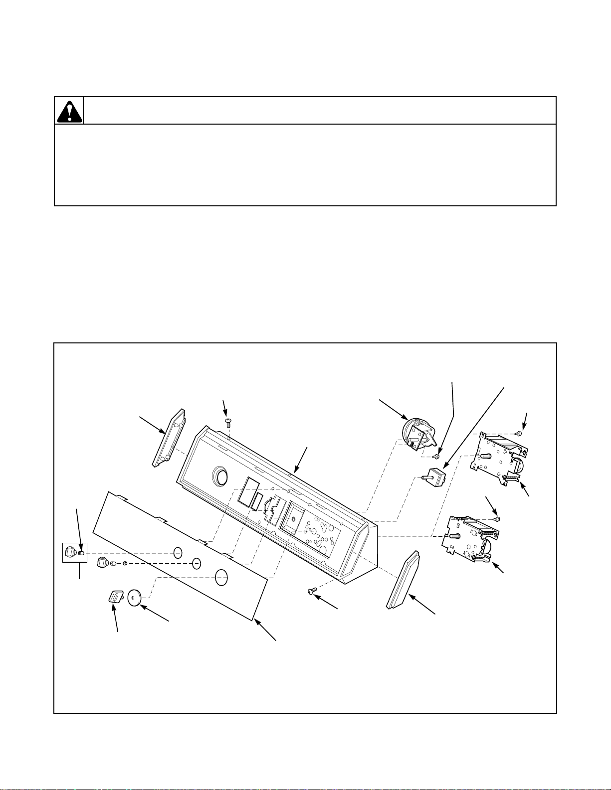
W435P
Eaton
Timer
Screw
End Cap
(Right)
Screw
Screw
End Cap
(Left)
Pressure
Switch
Control Hood
Assembly
Graphic
Panel
Clip
Control
Knob
Assembly
Timer
Knob
Timer Knob
Skirt
Mallory
Timer
Screw
Screw
Temperature
Switch
Service Procedures
IMPORTANT: When reference is made to
directions (r ight or left) in this manual, it is from the
operator’s position facing the front of the washer.
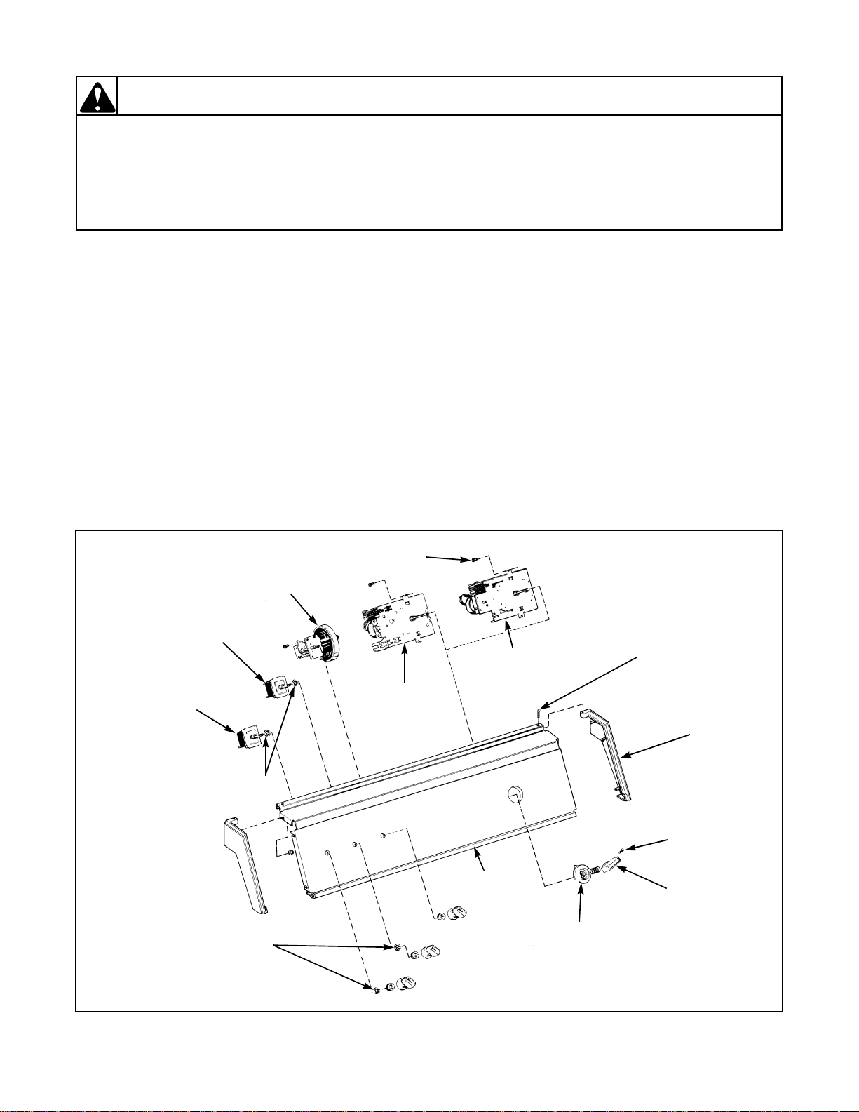
20. CONTROL HOOD ASSEMBLY (Models
BA4121, BA4120 and BA3110)
Refer to Figure 7.
a. Remove six screws (3 on top and 3 at lower
front) holding hood assembly to control hood
rear panel and cabinet top.
NOTE: Refer to appropriate wiring diagram when
rewiring component parts.
b. Disconnect wires from component parts and
carefully remove components from control
hood assembly.
TO REMOVE CONTROL HOOD END CAPS
Remove end caps by carefully prying caps out of
slots in ends of hood.
32305
GRAPHICS PANEL, CONTROL HOOD AND CONTROLS
© Copyright, Alliance Laundry Systems LLC – DO NOT COPY or TRANSMIT
Figure 7
17
Section 5 Service Procedures
To reduce the risk of electric shock, fire, explosion, serious injury or death:
• Disconnect electric power to the washer before servicing.
• Never start the washer with any guards/panels removed.
• Whenever ground wires are removed during servicing, these grou nd wires must be
reconnected to ensure that the washer is properly grounded.
W003
WARNING
End
Cap
Pressure
Switch
Timer
(Mallory)
Temperature
Switch
Speed
Switch
(Action)
Timer
Attaching Screw
Timer
(Singer)
Panel
Assembly
Screw
Lockwashers
Lockwashers
Control
Panel
Timer Knob
Indicator
Timer Knob
Set Screw
Timer
Knob
21. CONTROL PANEL (Models BA2411, BA2410
and BA2300)
Refer to Figure 8.
a. Remove panel assembly screws and lift
assembly off panel support.
b. Remove end caps.
c. Remove timer knob assembly.
NOTE: When reinstalling timer knob assembly, pin
in timer shaft must be positi oned i n slot t imer kno b
indicator.
d. Pull knobs off temperature and speed (action)
switches (if present), and remove knurled nuts
and lockwashers holding switches to control
panel.
NOTE: Lockwashers must be between switch and
control panel when installing switch.
e. Pull knob off pressure switch and remove
screws holding switch to control panel.
f. Remove screws holding timer to control panel.
NOTE: When installing timers, shown in Figure 8,
the horizontal and vertical tabs on front plate of
timer must seat completely into the “cross shaped”
holes on the control panel bracket, Figure 8, and
that the two timer hex head attaching screws are
torqued down between 12 a nd 18 inch pounds (14 to
21 cm-kg).
18
© Copyright, Alliance Laundry Systems LLC – DO NOT COPY or TRANSMIT
Figure 8
32305
Section 5 Service Procedures
To reduce the risk of electric shock, fire, explosion, serious injury or death:
• Disconnect electric power to the washer before servicing.
• Never start the washer with any guards/panels removed.
• Whenever ground wires are removed during servicing, these grou nd wires must be
reconnected to ensure that the washer is properly grounded.
W003
WARNING
T erminal Blo ck
Plug
Timer
Attaching
Screws
Locking
Tabs
Control Hood
Mounting
Plate
Timer
Attaching
Screws
Cross
Shaped
Holes
IMPORTANT: To avoid an open circuit, DO NOT
pull on terminal block wir es wh en r emoving bloc ks
from timer as this could damage wires or terminal
crimping.
Before attachi ng wire harness terminal blocks to
timer, make sure all male terminals on timer are
straight and are capable of accepting terminals
from wire harness terminal blocks.
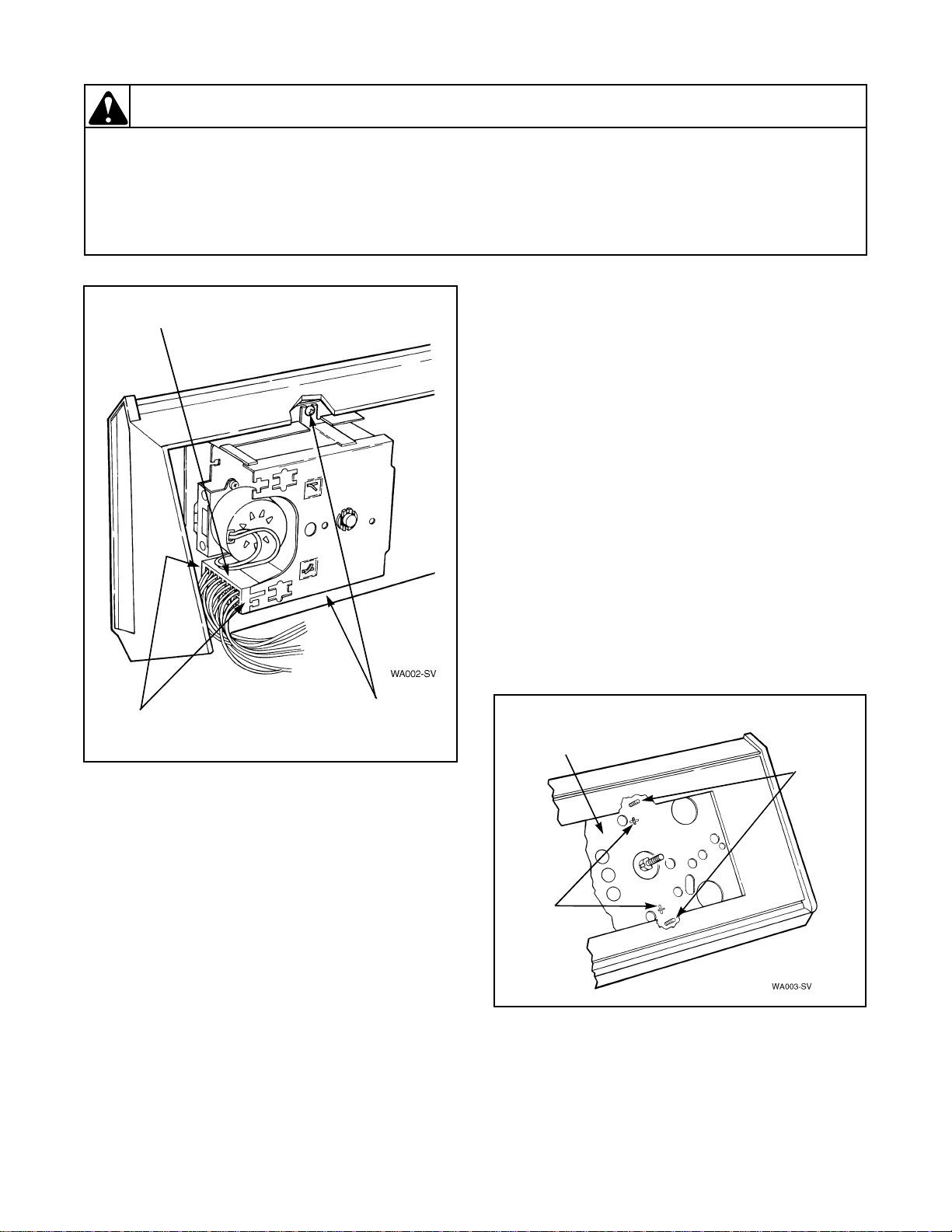
NOTE: When installing timer, be sure timer is
installed correctly and is securely mounted to
bracket on control hood. Refer to Figure 10.
e. The horizontal and vertical tabs on front plate
of timer must seat completely into the slots on
the control hood mounting br acket, and that the
two screws are torqued down between 12 and
18 inch pounds (14 to 21 cm-kg).
IMPORT ANT : T o avoid timer damage, do not allow
timer to be struck o n co rners, edges o f fra me, o r on
timer shaft.
Figure 9
22. TIMER (Models BA4121, BA4120 and
BA3110)
Refer to Figure 7.
a. Remove six screws (3 on top and 3 at lower
front) holding hood assembly to control hood
rear panel and cabinet top.
b. Unscrew timer knob from timer shaft (right
NOTE: DO NOT attempt to repair timer.
hand thread), then remove timer knob skirt.
c. Remove two screws holding timer to control
hood mounting plate. Refer to Figure 9.
Figure 10
d. Disengage wire harness terminal bloc k pl ug(s)
from timer by pressing in on movable locking
tabs (located on each side of terminal block
plug) and pulling away from timer. Refer to
32305
Figure 9.
© Copyright, Alliance Laundry Systems LLC – DO NOT COPY or TRANSMIT
19

Section 5 Service Procedures
To reduce the risk of electric shock, fire, explosion, serious injury or death:
• Disconnect electric power to the washer before servicing.
• Never start the washer with any guards/panels removed.
• Whenever ground wires are removed during servicing, these grou nd wires must be
reconnected to ensure that the washer is properly grounded.
W003
WARNING
Terminal
Block
Plug
Locking
Tabs
23. TIMER (Models BA2411, BA2410 and
BA2300)
Refer to Figure 8.
a. Remove panel assembly screws and lift
assembly off panel support.
b. Loosen setscrew holding timer knob to timer
shaft, then remove knob, spring and ti mer knob
indicator.
NOTE: DO NOT attempt to repair timer.
c. Disengage wire harness termi nal bloc k pl ug(s )
from timer by pressing in on movable locking
tabs (located on each side of terminal block
plug) and pulling away from timer. Refer to
Figure 11.
d. Remove the two hex head screws holdi ng timer
to rear of control panel bracket.
NOTE: When installing timer, be sure timer is
installed correctly and is securely mounted to
bracket on control hood. Refer to Figure 8.
e. The horizontal and vertical tabs on front plate
of timer must seat completely into the crossshaped holes on the control hood mounting
bracket. Torque down the screws between 12
and 18 inch pounds (14 to 21 cm-kg).
IMPORT ANT : T o avoid timer damage, do not allow
timer to be struck o n co rners, edges o f fra me, o r on
timer shaft.
24. TEMPERATURE SWITCH OR SPEED
(ACTION) SWITCH
Refer to Figure 7 or 8 for switch removal,
depending on model.
NOTE: Refer to appropriate wiring diagram when
rewiring switch.
25. PRESSURE SWITCH
Refer to Figure 7 or 8 for switch removal,
depending on model.
NOTE: Refer to appropriate wiring diagram when
rewiring switch.
IMPORTANT: When installing pressure switch,
blow air through pressure hose before connecting
Figure 11
IMPORTANT: To avoid an open circuit, DO NOT
pull on terminal block wir es when r emov ing blocks
from timer as this could damage wires or terminal
crimping.
hose to switch to remove any conde nsation that may
have accumulated in the hose.
When the pressure hose has been removed and
replaced several times, the end of the hose may
become enlarged, and does not seal properly.
If hose is enlarged, cut approximately 1/2" to 3/4"
off the end of the hose and rei nstall hose on pressur e
switch.
Before attaching wire harness terminal block to
timer, make sure all male terminals on timer are
straight and are capable of accepting terminals
from wire harness terminal block.
20
© Copyright, Alliance Laundry Systems LLC – DO NOT COPY or TRANSMIT
32305
Section 5 Service Procedures
To reduce the risk of electric shock, fire, explosion, serious injury or death:
• Disconnect electric power to the washer before servicing.
• Never start the washer with any guards/panels removed.
• Whenever ground wires are removed during servicing, these grou nd wires must be
reconnected to ensure that the washer is properly grounded.
W003
WARNING
Loading
Door
Hinge
26. GRAPHIC PANEL (Models BA4121, BA4120
and BA3110)
Refer to Figure 7.
a. Remove six screws (3 on top and 3 at lower
front) holding hood assembly to control hood
rear panel and cabinet top.
b. Disconnect wires from component parts and
carefully remove components from control
hood assembly.
NOTE: Refer to appropriate wiring diagram when
rewiring component parts.
c. Bend tabs on graphic panel (located inside of
control hood) straight out toward rear of hood.
d. Carefully remove graphic panel off front of
control hood.
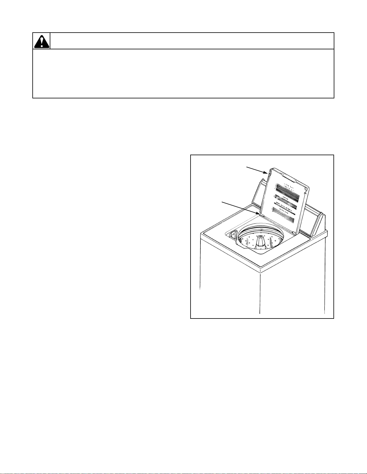
27. LOADING DOOR
Refer to Figure 12.
a. Depress tab on either hinge, then slide hinge out
of loading door and bushing in cabinet.
b. Tilt loading door slightly and slide door and
hinge out of opposite bushing.
Figure 12
32305
© Copyright, Alliance Laundry Systems LLC – DO NOT COPY or TRANSMIT
21
Section 5 Service Procedures
To reduce the risk of electric shock, fire, explosion, serious injury or death:
• Disconnect electric power to the washer before servicing.
• Never start the washer with any guards/panels removed.
• Whenever ground wires are removed during servicing, these grou nd wires must be
reconnected to ensure that the washer is properly grounded.
W003
WARNING
No. 254P4P
Agitator Hooks
Agitator
To reduce the risk of electric shock or
injury to persons, disconnect the washer
power cord before servicing the washer. If
water is present in the washtub, spin and
pump out before attempting to remove t he
drive bell and seal seat assembly.
WARNING
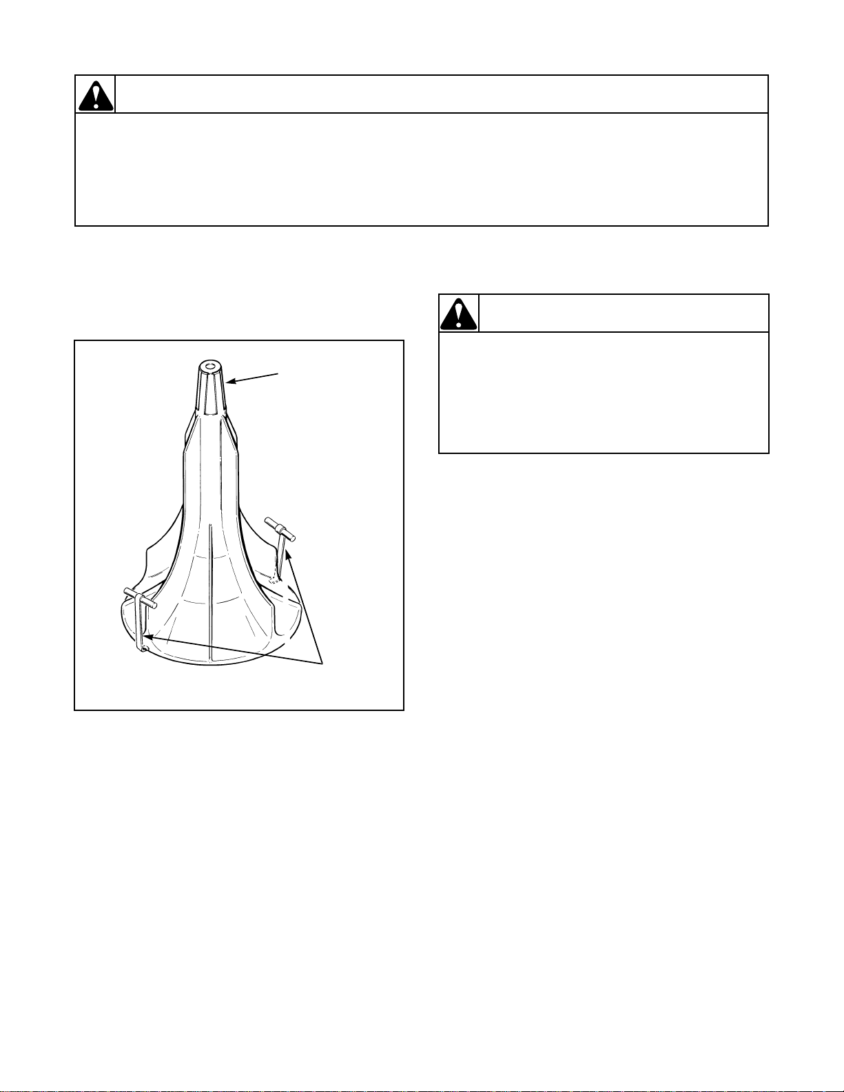
28. AGITATOR (Short Post Models)
a. Open loading door.
b. To remove agitator by hand, place two agi tator
hooks, No. 254P4P, under bottom edge of
agitator. Refer to Figure 13.
29. AGITATOR, DRIVE BELL AND SEAL
SEAT ASSEMBLY (Short Post Models)
a. Open loading door.
b. To remove agitator by hand, pla ce two agita tor
hooks, No. 254P4P, under bottom edge of
agitator. Refer to Figure 13.
IMPORTANT: Hooks should be positioned 180
degrees of each other, and must be placed under
agitator fin for great er stabi lity. If hooks are placed
between the fin ar ea, da mage to a gitat or may oc cur.
c. Using a rocking motion (back and forth)
carefully lift agitator off drive bell.
d. Remove the screw and o-ring washer from the
top side of the drive bell.
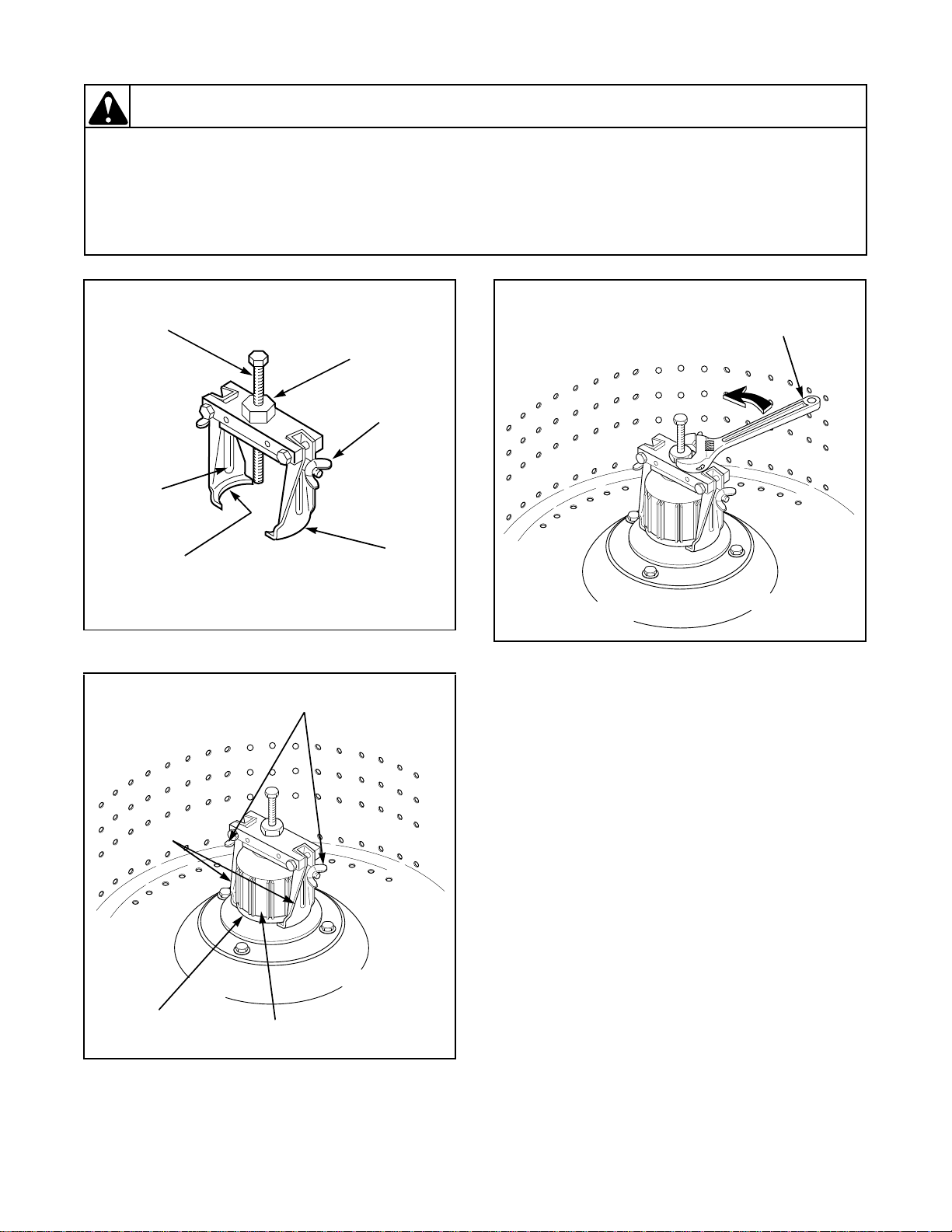
NOTE: To remove the drive bell from the
Figure 13
transmission shaft wi ll r equire using the No. 294P4
Drive Bell Tool. Refer to Figure 14.
IMPORTANT: Hooks should be positioned 180° of
each other, and must be placed under agitator fin
for greater st ability . If hooks ar e placed between th e
fin area, damage to agitator may occur.
e. Back bolt out of tool approximately three
quarters of the way.
f. Place tool over the bell, making sure indent on
jaw lines up with wide slots on the bell. Refer
c. Using a rocking motion (back and forth)
carefully lift agitator off drive bell.
to Figure 15.
g. Screw the bolt down through hole in top of bell
until bolt bottoms out in the hole in the
transmission shaft.
h. Place lip of each jaw under bottom edge of
drive bell, making sure indent on jaw lines up
with wide slots on bell. Then tighten the two
22
© Copyright, Alliance Laundry Systems LLC – DO NOT COPY or TRANSMIT
wing nuts to hold jaws firmly against drive bell.
Refer to Figure 15.
32305
Section 5 Service Procedures
To reduce the risk of electric shock, fire, explosion, serious injury or death:
• Disconnect electric power to the washer before servicing.
• Never start the washer with any guards/panels removed.
• Whenever ground wires are removed during servicing, these grou nd wires must be
reconnected to ensure that the washer is properly grounded.
W003
WARNING
L021
Bolt
Large
Nut
Wing
Nut
Jaw
Jaw
Lip
Indent
WA189-SV
Wing
Nut
Jaws
Wide
Slot
Drive
Bell
WA190-SV
Turn Adjustable
Wrench Counterclockwise
to Remove Drive Bell
Figure 14
Figure 16
i. Use an adjustable wrench and turn the large nut
on tool COUNTERCLOCKWISE to pull
drive bell from transmis sion output shaft. Refer
to Figure 16.
IMPORTANT: If large nut is turned clockwise
when pulling drive bell, you will twist off the 1/4
inch bolt.
j. Turn the 1/4 inch bolt out of transmis sion shaf t
and remove tool and drive bell from washer.
k. Loosen the two wing nuts and remove drive bell
from tool.
l. Carefully pry the old seal out of the drive bell
and clean any foreign materials from the bell.
IMPORTANT: We recommend that both the seal
seat and the seal head be replace d together in pairs.
DO NOT replace only one of the two.
m. Install the new seal into the drive bell.
n. Remove the seal head from the hub and clean
Figure 15
any foreign material from the hub seal
mounting area.
32305
© Copyright, Alliance Laundry Systems LLC – DO NOT COPY or TRANSMIT
23
 Loading...