

Page 1
GasClam Instrument User Manual V1.3
GasClam Instru ment User Man ual part number: 25001
Page 2

Gasclam Ion Science Ltd
Pag e 1 of 30
Page 3

Gasclam Ion Science Ltd
Introduction to GasClam ................................ ................................ ................................ ................................ ....... 3
Getting Sta rted ................................ ................................ ................................ ................................ .................... 5
Packing list................................ ................................ ................................ .......................... ...... ........................ 5
Turning on the Gasclam................................ ................................ ................................ ................................ ....... 5
Physical Characteristics................................ ................................ ................................ ................................ ........ 6
How the Gasclam Works................................ ................................ ................................ ................................ ....... 7
Battery Change................................ ................................ ................................ ................................ .................. 7
Software I nstallation................................ ................................ ................................ ................................ ............. 8
System Requirements................................ ................................ ................................ ................................ .......... 8
Running the installation software................................ ................................ ................................ ............................ 8
Basic screen................................ ................................ ................................ ................. ............... ...................... 9
Setup................................ ................................ ................................ ................................ ................................ .13
Sampling Rate................................ ................................ ................................ ................................ .................. 13
Device ID................................ ................................ ................................ ................................ ........................ 13
Venting................................ ................................ ................................ ................................ ........................... 14
Unit date and time................................ ................................ ................................ ................................ .............14
Erasing Data Memory................................ ................................ ................................ ................................ .......... 14
Switching off the unit................................ ................................ ................................ ................................ .......... 14
Update firmware................................ ................................ ................................ ................................ ................ 15
Return to main screen................................ ................................ ................................ ................................ .........15
Downloading................................ ................................ ................................ ................................ .................... 16
Viewing D ata ................................ ............... ................. ................................ ................................ ...................... 17
Selecting file for display................................ ................................ ................................ ................................ .......17
Data Display Options........................ ........ ................................ ................................ ................................ .......... 17
Sampling data................................ ................................ ................................ ................................ ...................18
Selecting data channel................................ ................................ ................................ ................................ ........19
Scale label................................ ................................ ................................ ................................ ....................... 20
Setting auxiliary axes................................ ................................ ................................ ................................ .......... 21
Changing the scale................................ ..................... ........... ................................ ................................ .............21
Service and Calib ration ................................ ................................ ................................ ................................ ........25
Unit calibration................................ ................................ ................................ ................................ .................. 25
Service................................ ................................ ................................ ................................ ............................ 25
User serviceable parts................................ ................................ ................................ ................................ ......... 25
User Serviceable Parts................................ ................................ ................................ ................................ .........26
Update L og................................ ................................ ................................ ................................ ......................... 29
Pag e 2 of 30
Page 4

Gasclam Ion Science Ltd
Electrical Apparatus for Potentially Explosive Atmospheres — General
Electrical apparatus for explosive gas atmospheres. Flameproof
PTTI EN 60079-11:2007
Directive 2004/108EC
Declaration of conformity
The manufacturer, Elok-Opava, hereby declares and confirms that the characteristics of the product conform to the technical
requirements stipulated by the technical standards. Furthermore, the manufacturer declares the product to be safe whilst adhering to the
correct conditions for its installation, maintenance and use.
Manufactur er: E lok-Opava spol s r.o., Sddek 17, 747 7 5 Velké Her altice, Czech Republ ic,
Product De scripti on: A landfill Gas mo nitor desi gned for in -situ bore hole monitor ing. T he entire cas ing is made from
solid sta inless st eel. T he bat tery pac k is in the upper p art of t he ho using in a flam e -proof casing. The measuring unit
consisti ng of fo ur gas se nsors is located in the i ntrinsica lly safe lower p art of t he housing. The valves, p ump a nd filter
assembly a re locat ed at th e bottom of the housing.
Author ised Subject: FT ZU, AO 210, NB 10 26, Pikartskd 7, 716 07 OSTRAVA-RADVANICE, IC0-00 577880
Type of Prote ction :
II 2G Ex d ib [ib] IIB T4
Cert ificate Numb er: Quality assura nce notification: FTZU 02 ATE X Q 025 acc ording t o EN 13980, CE 1026
F TZU 07 A TE X 0105X
Method of determining conformi ty: The products conformity with the respective requirements of directive 94/9/EC and
2004/108/EC
- it was compared with the submitted documentation
- it was tested according standards
List of Technical Regulations and Standards:
02600-00-001,NKO
PTTI EN 60079-0:2006
Requirement
PTTI EN 60079-1:2004
enclosures `d'
Explosive Atmospheres — equipment protection by Intrinsic Safety T
Name: Ing. Jiri Kl ein Position: Mana ging Di rector
Signa ture : Dat e: 03/06/20 08
Pag e 3 of 30
Page 5

Gasclam Ion Science Ltd
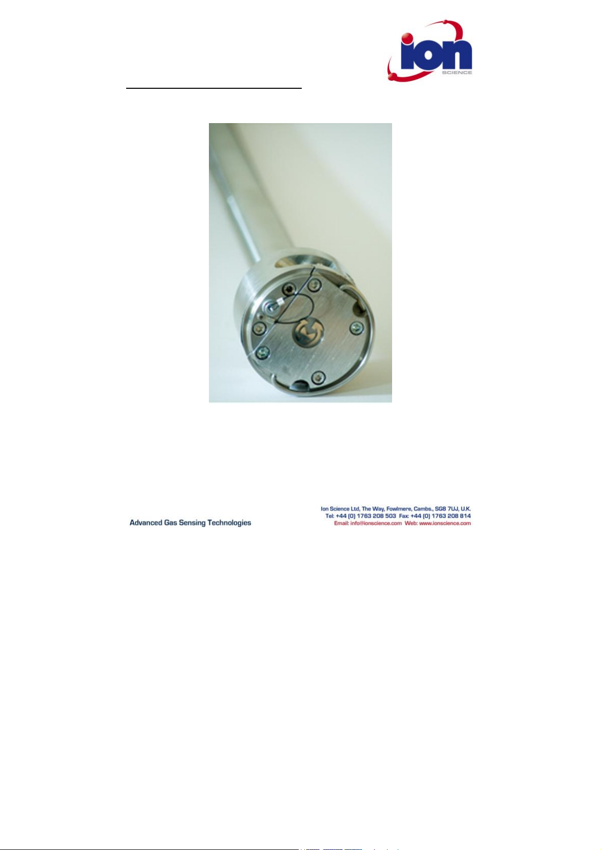
Introduction to GasClam
GasClam is the world’s first in-sit u borehole gas m onitor, suitable for the detecti on of a wide r ange of gasses com monly
found in borehole monitoring including m ethane (CH4), Carbon Diox ide (C O2) an d Oxygen (O2). In addition to this t he
GasClam c an detect temp erature, barometr ic press ure a nd borehole pressure.
All of thes e read ings can be take n at user-set intervals, providing an i nvaluable s et of data t o the use r. The defau lt
setting f or the G asclam is to take readings every h our, g iving it a pproxima tely th ree mo nths ’ operational life before it
must be co nnecte d to the Gasclam softwa re for data retr ieval. While co nnecte d to the s oftware the sett ings of t he
Gasclam u nit can be altered incl uding the frequenc y at which rea dings are logged by the o nboard memory.
In addition to the se nsors already mentioned, the Gasclam can be upgra ded wit h a photo ionis ation detector (PID) for
detection of V olatile Organic Compounds (V OC’s), a C arbon M onoxide (CO) sensor a nd a wate r dept h sensor s hould the
data be required.
Pag e 4 of 30
Page 6
Gasclam Ion Science Ltd
Getting Started
Packing list
Please take a little t ime to examine t he contents of the Gasclam Packa ge.
Item Descripti on Qty
Turni ng on the Gasclam
To stop t he Gascla m press the button for two sec onds, when it h as stopped the L ED will stop flash ing, th is equates to
‘sleeping’ m ode
Barbs (Fitt ed) 3
Blank (NOT Fitted) 1
Tool for remo ving Ba rbs or B lank 1
Length of p ipe ( 30cm) 3
Snorkel fi lter 1
Battery A llen Key 1
Comms cable 1
Start c able 1
Manual and soft ware (on C D) 1
Rubber C ollar 1
GasClam Unit 1
1.5v Duracell Batt eries (F itted) 2
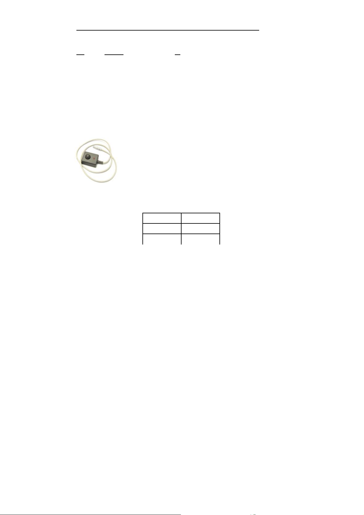
The Gasc lam can be switched on and off using the remot e. The r emote c onnects t o the
commun ication p ort on t op of th e Gasc lam
.
To start t he Gasclam hol d the button do wn for two seco nds, the r ed LED will flas h rapidly
indicating t he Gasclam h as start ed and is currently going through the pr ocesses i n a samp ling
cycle, t his equates t o ‘sampling’ mo de.
After the s ampling processes have fi nishe d the red L ED flash es inter mittent ly, this e quates t o
the ‘measuring’ mod e.
No flashing Sleeping
Rapid flash Sampling
Intermittent flash Measuring
Pag e 5 of 30
Page 7
Gasclam Ion Science Ltd
1 8
2
Getting Started
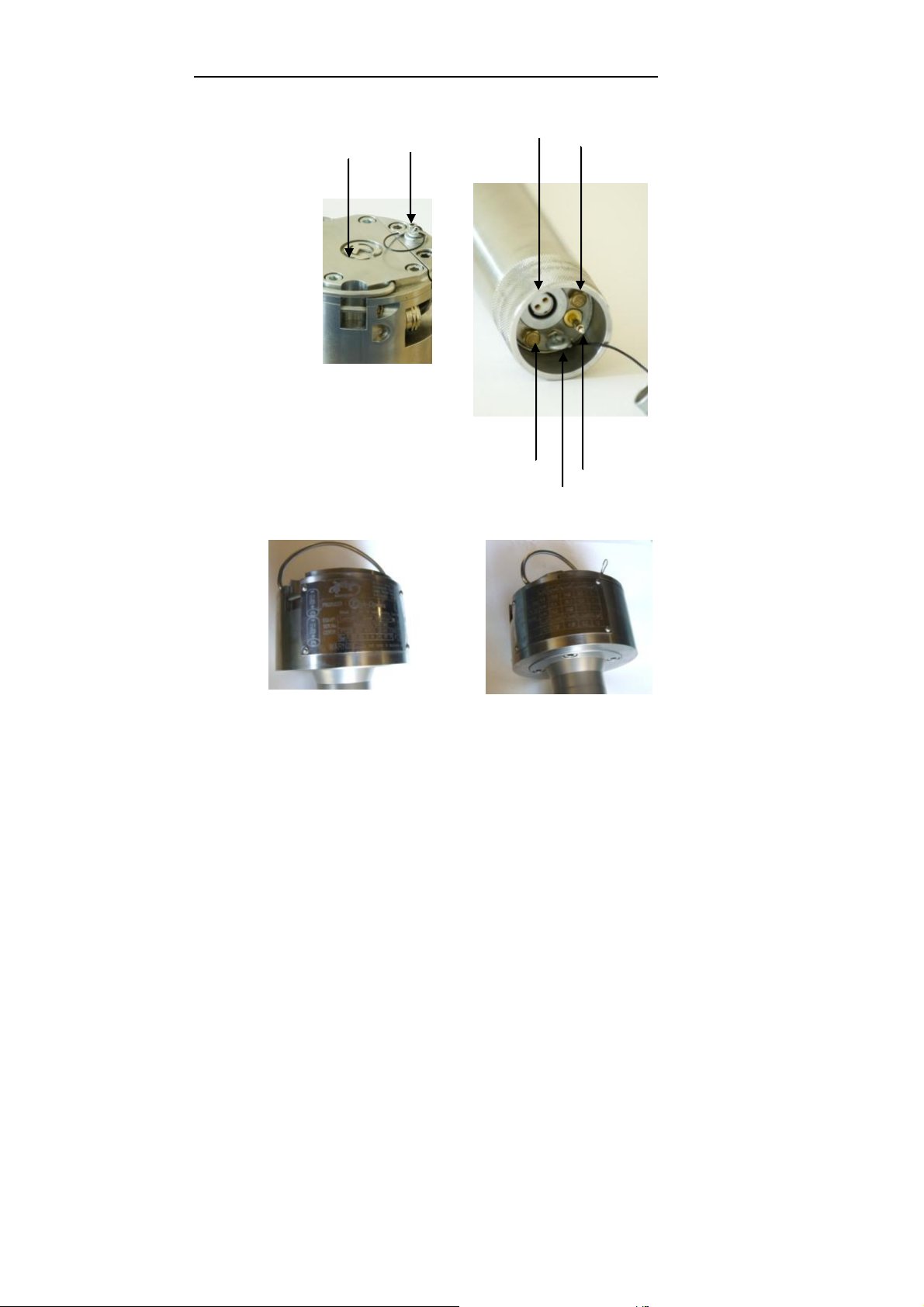
Physical Char acter istics
1. Communication p ort
2. Pressure t ransducer port
3. Pressure t ransducer port cap
4. Gas inlet
5. Gas Out
6. Water sensor
7. Pressure t ransducer hook
8. Battery compartme nt lid
4
7
Pictures of the Gasc lam Identificati on plates, detailin g the spec ifications of the unit (p. 24)
5
6
Pag e 6 of 30
Page 8
Gasclam Ion Science Ltd
Getting Started
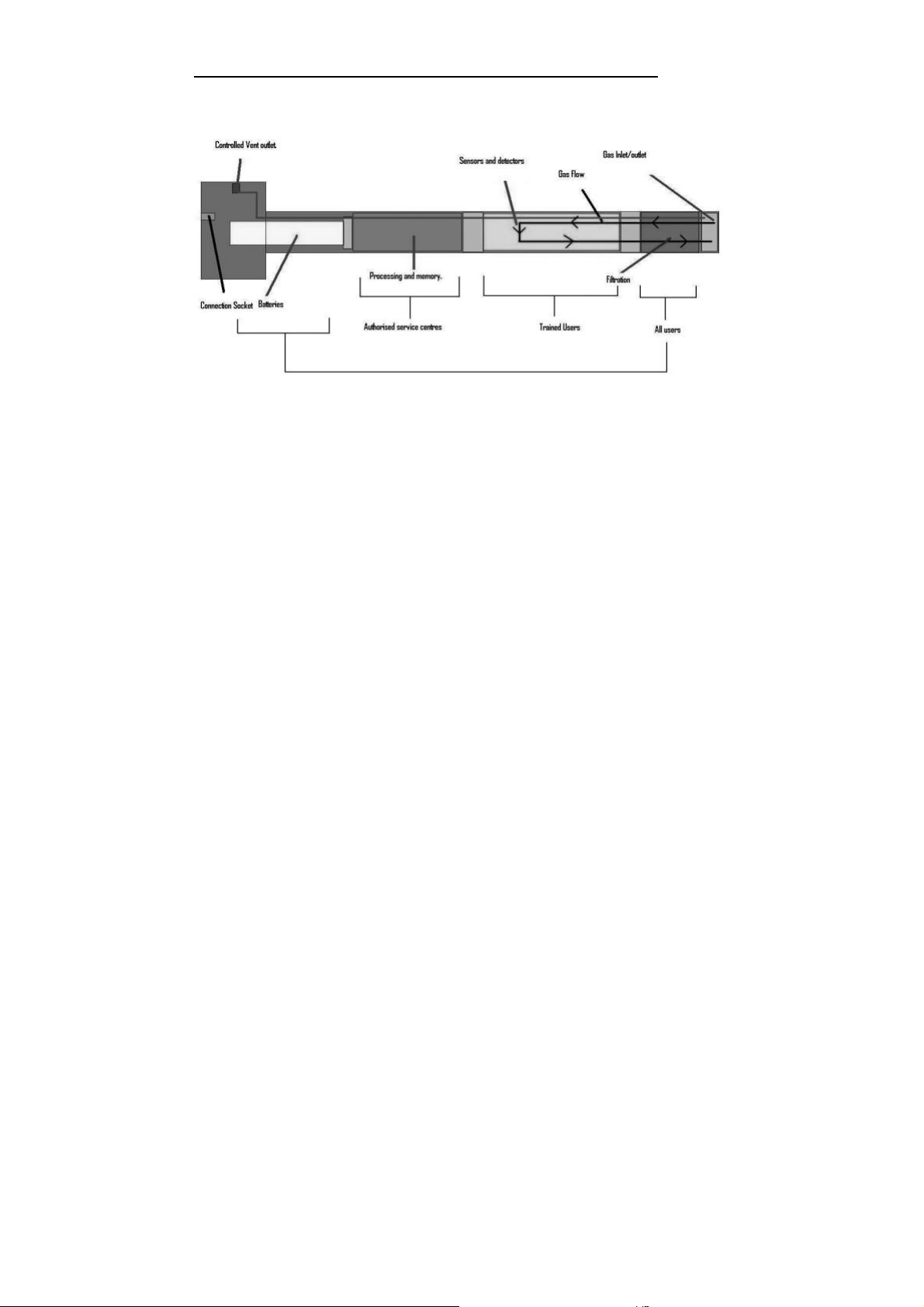
How the Gasclam Works
Batt ery Cha nge
The Batte ries fitted t o the GasClam will last up to th ree mo nths de pending on type of batter ies, t he operat ing
temperature and t ime seq uence se lected.
Only change batt eries i n a safe are a.
The batter y compartment is accessed by remov ing the 4 screws f rom the battery c om partme nt lid, see diagra m. To
remove t he batteries tilt th e Gasc lam u ntil they fa ll out. R eplace with the stipulated batter ies positive ter minal facing
down.
Optimum battery l ife is based on 1 hou r sampling.
The Gasc lam takes t wo D cell batteries.
NB Do not mix old a nd new batter ies withi n the sam e unit, chang e bo th batter ies at the sa me time . Failure
to do so will re duce battery life of the new cell fitt ed.
Pag e 7 of 30
Page 9

Gasclam Ion Science Ltd
Software Installation
System Require ment s
The Gasc lam software ne eds 30MB free space o n the hard disk fo r instal lation.
The programme will run o n the fo llowing platforms:
- Windows 98
- Windows 98 Second Edition
- Windows 2000 service pack 3
- Windows ME
- Windows Server 2 003
- Windows XP service pack 2
- Windows Vista
The program me ne eds .Net Fr amework 2.0 (x 86) insta lled t o run properly. Th is version is included on the software CD,
alternativ ely it ca n be downloade d from th e Microsoft w ebsite.
To install . Net Fra mework 2.0 (x 86) from the CD o pen the DOTNETF X f older an d do uble clic k Windo wsinsta llerKB893803 -V2-x8 6
The guide will take y ou thr ough the instal lation process st ep by ste p.
Running t he installatio n software
Insert the installat ion CD; t he inst allatio n program s hould automat ically begin. If t his option is disab led, r un the
“setup.exe” program me man ually (found on the insta llation CD ).
The guide will take y ou thr ough the instal lation process st ep by ste p.
The defau lt location for th e Gasc lam soft ware is:
C:\Program Files\ Salamander\G asClam \
Pag e 8 of 30
Page 10

Gasclam Ion Science Ltd
Software Installation
Basic screen
Connecting
The Gasclam is connecte d t o a computer us ing the supplied c able between the c ommu nication port on top of the
Gasclam an d a s erial port on. If t he comp uter d oes not have a ser ial port use a st andar d USB/S erial conv erter.
You can either co nnect th e unit bef ore or after starting t he softwa re. If the soft ware is opened b efore t he Gasclam is
attached the scree n appears as below. I n this m ode the options av aila ble are to v iew data (see later) or to clos e th e
application.
Pag e 9 of 30
Page 11

Gasclam Ion Science Ltd
Software Installation
On Line Sta tus of t he Gasclam
After the Gasclam is co nnected th e screen will update (si milar to b elow) with the d evice ID is displayed i n box 1.
The windo w is d ivided in to 3 s ections, navi gation tabs (vie w data, do wnload, setup and c alibration), Online Stat us a nd
Last Rea ding Stored. This section covers t he on line status.
Online Status displays the cu rrent st atus of th e un it. T he d efault time inter val fo r the scre en to upd ate w ith data fr om
the G asclam is 1s, this ca n be c hanged by right clicking t he soft ware window and se lecting the ‘change r efresh data
interval’
Pag e 10 of 30
Page 12

Gasclam Ion Science Ltd
Software Installation
Battery st atus – disp lays bat tery vo ltage alongsid e a po wer bar, the bar ch anges c olour accordin g to cap acity pr oviding a
rough g uide to bat tery life*.
Green: ca pacity is f ine fo r a long samplin g period
Orange: B atteries need to be replace d very so on
Red: Replace batteries im mediatel y.
*The v oltag e i n the batte ry will decrease when the Gasc lam is sam pling due to a dr ain on the batteries, this is the
voltage th at should be used to assess battery condition.
Note. If th e batte ry ca pacity is no longer sufficient for the running of t he unit durin g a programme t he unit automatica lly
interrupts t he cycle and switc hes to sle eping m ode. T he data is stored in t he flas h memo ry ther efore th e data will r emain
on the Gasclam even if the batteries are complete ly flat. Also it is p ossible to replace t he bat teries withou t wiping th e
memory.
Samples left – displays the re maining number of sam ples that can b e store d in the memo ry. Sam ples take n/cou nt – When
the Gasclam is in sleeping mod e this reads ‘samp les t ake n’ indic ating how m any samp ling points are stored on t he
memory. When the G asclam is in sampling mode it re ads ‘Sample count’ a nd displays the number of fi nished cyc les an d
the tot al n umber of cycles i n the pro gramme. For examp le, 254/4500 means th at 25 4 cyc les fro m 4500 re qu ired cycles
have f inished. Th e maxim um numb er of sa mple the G asclam can s tor e is 6 5000. If t he Gasclam was set to hourly
sampling this eq uates to 5 417 days.
Sampling every - shows the per iod between indivi dual measuring cyc les. For example, value “10 m in.” mea ns that
sampling frequency is 10 minutes.
Finish on – displays t he date and time t hat the s ampli ng prog ramme will finish on.
Serial n umber – displays t he seria l number of the unit
COM port – displays which p ort the unit is connected t o.
Status – disp lays the mode of the u nit:
When the unit is running a programme th e follow ing mod es are p ossible:
Sampling – the Gascl am is activ ely mak ing a m easure ment.
Measuring – the Gascl am is bet ween s ampling periods.
When the Gasclam is not running a programme the following m odes ar e possible:
Sleeping – the unit is not running a program me. In t he mod e data ca n be d ownloaded and programm ed.
Clear flas h – the unit is erasi ng flas h memo ry data
If the G asclam is no t funct ioning c orrectly the status will r ead ‘undefi ned stat us,’ if this occurs contact custo mer s ervices
immediately.
Pag e 11 of 30
Page 13

Gasclam Ion Science Ltd
Software Installation
“START/STOP” Bu tton– this has s everal mod es: The unit is in sle eping mode, to
Firmware – shows t he firm ware v ersion in t he unit. A lwa ys use the s oftware des ignat ed for t he given f irmware vers ion.
Last reading stor ed
The last rec orded val ues are displayed in the ‘Last R eading Stored ’ box. If t he samp ling cyc le has sta rted, th ese va lues
will read ‘measu ring ’ and are updat ed throughout the s amplin g process.
The displayed ranges of individual sensors a re as follows:
Methane – 0-100% with precisio n of 2 decimal places
Carbon Dioxide – 0- 100% with precis ion of 2 decim al places
Oxygen – 0 -25% with precis ion of 2 decim al places
Gas Pressure – 0-10mbar with prec ision of 1 decima l place
Barometr ic Pressur e – 0-115mbar with precision of 2 decim al places
Temperat ure - -50°C to +50°C with precis ion of 2 decim al places
Optional Water Leve l – 0- 10m w ith precisi on of 2 decima l places
Optional CO sensor 1 PPM 0-1,0 00PPM or VOC 1 PPM 0-4,0 00PPM
The precis ion of t he display d oes not c orrespond to t he precisi on of the sensors . T his informa tion is inclu ded in t he
technical specification section tow ards th e end of this ma nual.
Display of voltage on AD conver ter -
Displaying voltage on the AD c onvert er for so me applications and testi ng, yo u have t o kno w the voltage for the AD
converter and the value of the AD conve rter of t he given se nsor. T hese v alues a re not normally dis playe d they ca n be
displayed using the me nu by pressing the right button o n your mouse. You can s witch off the d isplay in t he same way.
start the Gasc lam left c lick the butto n.
The unit is activ ely s ampling, it ca n be stoppe d by left clicking the butt on, aft er
this has fi nished the butto n changes to:
The unit is b etween samp les and the programme can be st opped by left click ing
the button.
Pag e 12 of 30
Page 14

Gasclam Ion Science Ltd
Setup
The Gasc lam is pr ogrammed in th e setup windo w and is accessed by left click ing the ‘se t u p’ naviga tion t ab, and the set
up windo w then appears as below.
Sampling Rat e
The sam pling rate is defin ed in th e Set Sampl e Rate box, th e fastest sam pling r ate is 3 m inutes (This is how long all the
processes take), t he longest 16 hours and 39 mi nutes.
Sample count
The num ber of sam ples to be take n ca n either b e set to the maximum possible by c licking the ‘Always Max imum’ button
or define d by the user in the Samp le count box. T he max imum f igure dis played is 65000 (to tal mem ory space ) minus the
number of stored samples, the use r defi ned value c an be up to a nd including this.
The est imated da te and time of the e nd th e pro gramme is disp layed under the text b utton. T his information is calculated
as follows: (Samp le cou nt * samp le rate ) + actual date and t ime.
Device ID
The user can sp ecify th e name of t he Gascl am in the Dev ice ID box. T his is useful if the re is mu ltiple G asclams on a site
as the b orehole numb er can be al located to the Gasclam. T his inform ation is used to create a f ilename whe n the data is
downloade d.
Pag e 13 of 30
Page 15

Gasclam Ion Science Ltd
Setup
Venting
The Gasc lam has fo ur ven ting mo des, the venting mode is selecte d in th e
Venting bo x (see below):
Always C losed – T he vent is always closed
Always Op en – Th e vent is a lways o pen.
Open once pe r day – The ve nt opens once a day for a p eriod of time
defined b y the use r
Open after every – T he vent opens after a period of time defined by the
user. (Ho w long does it o pen for XXX)
Unit da te and t ime
The time a nd date of the unit and c omput er are displayed in the Date
and Time box, thes e are synchr onised by left clicki ng the Set Tim e tab.
The date a nd time is not st ored when the unit is s witche d off or when
the batteries run o ut or ch anged.
Note. The time on the unit is likely to diffe r from the co mpute rs if the
device was programmed o n a diff erent co mputer to the one it no w is
connected to.
Erasing D ata Memory
To erase all the d ata from t he flas h memor y left c lick the Erase m emory butto n. The status will change to ‘C lear Flash’
during t his process , when this is fi nished to sta tus will cha nge to ‘Sleeping ’
Warning – This pr ocess er ases m emor y permanent ly. Make sure you ha ve downlo aded the data
from t he uni t int o your comput er.
Switching off the unit
If the u nit is not g oing to b e used fo r a long period it is rec ommen ded t hat it is t urned off us ing t he ‘ OFF’ button, this
reduces t he disch arge fr om the batteries.
When the off butt on is clic ked a mess age w ill appear to ask if you re ally wan t to s witch off.
Pag e 14 of 30
Page 16

Gasclam Ion Science Ltd
Setup
If the Yes button is clicked the following appears:
The Gasc lam will t urn off after th e commu nication cable is disconnected, u ntil then the ma in scree n will appear as below:
The Gasc lam will t urn back on when the data cab le is att ached a gain.
Update firmwar e
Nee d to check wit h ION Science
Retur n to main screen
To return to t he Gasclam software’s m ain window use the back but ton.
Pag e 15 of 30
Page 17

Gasclam Ion Science Ltd
Setup
Downloading
To downlo ad the Gasclam l eft click the ‘ Download’ b utton. Th is opens a sta ndard Win dow’s ‘sa ve as ’ windo w. The
default fil e name is the d evice ID f ollowe d by the time a nd date.
After choosing th e file nam e and l ocation the do wnload begins when save is clicked, the length of the d ow nloa d will
depend upon the a mount of data.
Two files a re produced a .GCL which is use d in the Gasclam soft ware a nd .CSV f ile which can be opened in exce l to plot
data in a s uitable manner for repo rts etc.
Pag e 16 of 30
Page 18

Gasclam Ion Science Ltd
Viewing Data
The data v iewer is accesse d via t he ‘Vie w Data’ navigati on butto n on the main sc reen.
Selecting file for displa y
If a data f ile has j ust been downloaded the s oftware remem bers its l ocatio n and can be acc essed by clicking ‘open’
To access any ot her file cl ick the ‘… ’ button this a llows you to browse thr ough your comp uters folders. The last fo lder
that was acc essed will open.
Dat a D isplay Options
There are 3 data v iew opt ions tha t can be accesses via t he Start -Stop Data, Cal ibration Data and Sampling Da ta bu ttons,
see below:
Start -Stop d ata
To display the sam pling l og of the unit click the ‘Start-Stop’ Data button. Information regardi ng when and ho w the unit
was starte d and sto pped, date the action was tak en, mem ory s pace left and sam pling freq uency a nd how many samples
was take n is reported, see below for an example.
Note. If th e Gascl am has stopped due to low batt ery a no te indicat ing t his will be left in t he code c olum n.
Pag e 17 of 30
Page 19

Gasclam Ion Science Ltd
Viewing Data
Sampling data
To display the sam pled da ta click the ‘Sampling- data’ butto n. T he following parameters are displayed, see examp le
below.
Date: in th e format dd/mm /yyyy hh:mm
CH4 %: Met hane % v/v
CO2 %: Ca rbon dioxide % v/v
O2 %: Oxyge n % v/v
CO: Carbon Monoxide or V OC: Volatile Or ganic Co mpound PPM
Dif (m bar): Diffe rential pressure between borehole and atmos phere. If the valu e is negative it means the pressure in
the boreh ole is lower tha n atmos pheric and if the press ure is positive it is h igher than atm ospheric.
Bar mbar: Barometric press ure
Temp C: Te mperat ure in degrees C elsius
H2O Leve l m
Battery (V): Battery cap acity in volts
It is possible to order the displayed data according to individual paramet er by clicking the colum n heade r, on e click
arranges th em in asc ending order two clicks arranges them in descending order.
To view t he data in grap hical form click t he Gra ph/Data vi ew to ggle butt on.
This o pens the Graph view window, sho wn on next page.
Graph/Data view
toggle button
Pag e 18 of 30
Page 20

Gasclam Ion Science Ltd
Viewing Data
Sele cting data channe l
To select a data c hannel cl ick t he desired param eter from the ‘Data Ch annel’ box, see below. M ultiple parameters can be
displayed by clicki ng more paramet ers.
Pag e 19 of 30
Page 21

Gasclam Ion Science Ltd
Viewing Data
Scale labe l
When dis playing multiple parameters up to two y-axes can be s elected using the ‘Sc ale-label’ drop do wn menu, see figure
below.
Pag e 20 of 30
Page 22

Gasclam Ion Science Ltd
Viewing Data
Set ting auxiliary ax es
Changing the scale
The scale of the y -axes can be c hanged using the min an d max b oxes indicated below. The scale can be changed by
either usi ng the up/down buttons next to t he M in Max b uttons o r by typ ing the re quired v alue in t o the fi eld and cl icking
on the box adjac ent to it i.e., to ch ange t he min value typ e the des ired v alue and t hen click in the Max box a nd the graph
will updat e.
Time axis
Time is displayed on the y-axis, this can b e scrolled throug h using t he scr oll bar u nderneat h.
Pag e 21 of 30
Page 23

Gasclam Ion Science Ltd
Viewing Data
Sele cting displayed group s of measured values
Pag e 22 of 30
Page 24

Gasclam Ion Science Ltd
Viewing Data
Impor t da ta into External Spreadshe et
Data is pr ovided as a CVS file and can be im porte d into var ious spreadshee ts for manipu lation. T his is normally d one
using the import f unction a nd selec ting delimited and the n selecti ng com ma as t he sepa rator.
Print gra ph
By pressi ng the “ Print graph” butt on, you c an print the actual graph.
Pag e 23 of 30
Page 25

Gasclam Ion Science Ltd
Viewing Data
Infogra ph
To display the all t he values of the param eters at any particular t ime right click ing t he graph at this p oint and the
Infograp h box will appear, s ee below.
Retur ning t o the ma in window
To return to t he main Gasc lam scree n click th e ‘Back ’ butt on
Pag e 24 of 30
Page 26

Gasclam Ion Science Ltd
Filte r
Braised sections
Service and Calibration
Unit calibrat ion
Calibratio n should only be carried out by a n aut horised Gasclam distribut or.
Service
The Gasclam should be regularly s erviced to ens ure correct and accurate operation. It is rec ommen ded t hat it s hould be
serviced a nd reca librate d every xxx months.
The Gasclam is ATE X cert ified for use in potent ially explos ive areas therefore it s hould o nly be s erviced by qualified
engineers. Failure t o do so will invalidate t he warranty.
User ser viceable parts
Inline filte r: This accesse d by u nscrewing the bottom section of the Gasc lam, s ee figure.
It should b e replaced regu larly, ce rtainly aft er a weeklo ng installation. T he instr ument s hould n ever be
operated without t he filter.
End sec tion, u n-screw by holding the two
braised section a nd turning a nti-c lockwise
Snorkel: The sn orkel should be c hecked r egularly, if ther e is a ny dam age re place imme diate ly
Collar: Inspect the collar re gularly, if there is any si gns of da mage r eplace immediat ely.
Pag e 25 of 30
Page 27

Gasclam Ion Science Ltd
Service and Calibration
User Se rviceable Par ts
Item Ref. Part Num ber Description
1 25039 Water Level Senso r (6m)
2 TBC TBC
3 25030 Communication Cable
4 25031 Push B utton Co ntrol
5 25032 Filter tub e
6 25033 Rubber Seal
7 25034 Membran e Filter
8 25035 Hose Barb Fittin g
9 25036 Hanger
10 2/SA5-20 Screw (controlled vent out let)
11 25037 Connecto r Cover
12 and 13 1/BA-03 Battery A lkaline MN 1300 D (2 off required)
14 25038 Enclosure Cover
Pag e 26 of 30
Page 28

Gasclam Ion Science Ltd
Service and Calibration
Pag e 27 of 30
Page 29

Gasclam Ion Science Ltd
Technical Specification
Sensor M ethod/typ e Range Resolution Accuracy Linearity
CH4 Infrared 0-100 % 0.01 % ± 5% of r eading ± 1 di git +/- 2% F SD or 10% rea ding
CO2 Infrared 0-100 % 0.01 % ± 5% of r eading ± 1 di git +/- 2% F SD or 10% rea ding
Oxygen Electrochemica l 0-25 % 0.1 % ± 5% of r eading ± 1 digit +/- 2% F SD or 10% reading
CO* Electrochemica l 0-2,00 0 PPM 1 PPM ± 5% of r eading ± 1 digit +/- 2% F SD or 10% reading
VOC* PID 0-4,00 0 PPM 1 PPM ± 5% of readin g ± 1 digit +/- 2% F SD or 10% rea ding
Environment Method / Ty pe Range Resolution
Barometr ic Piezoelectr ic 800-1200 m b 0.1 mb
Borehole Piezoelectr ic -100 - +100 mb 0.01 mb
Temperat ure Internal C hip -5°C to +50°C or 41° F to 12 2°F 1°C or 1°F
Water dept h* Piezoelectric 0 – 10 m 0.1m
* Option al
Memory 6300 t ime / date stamped rea dings
Power Internal x 2 Alkaline D-cells
Battery Life 3 mo nths (Base d on hourly sa mpling)
Case High Quality Stai nless Ste el
Weight 6 kg or 13.2 lb
Protection IP – 68 (conti nuous s ubmers ion)
Operatio n –5 - +50 °C or 41° F to 12 2°F
Approva ls CE, EMC, ATEX, 0105 X, Ex II 2G, Ex d ib [ib] IIB T 4
Certification ratin g Ex 2G Ex d i b [ib] IIb T4
Certificate number FTZU 07 ATEX 0105 X
Pag e 28 of 30
Page 30

Gasclam Ion Science Ltd
Update Log
Manual Ve rsion Amendme nt Date Upd ated Instrum ent Firmw are Instrument Software
GasClam V 1.0 Layout and C ontent
Updated. Updated t o
version 1.1
GasClam V 1.1 Spare parts list and
diagrams for use rs added.
Updated to version 1.2
GasClam V 1.2 InfoGraph imag e update d
and general Layout of
Manual updated. Updated
to versio n 1.3
09/04/09 06.04.7 5 3.7.8
27/04/09 06.04.7 5 3.7.8
06/06/09 06.04.7 5 3.7.8
Pag e 29 of 30
 Loading...