

Invicta TI-14 Operator's Manual
OPERATORS MANUAL
SHAPER
by
INVICTA
Model
TI-14
INCLUDES VERSIONS:
TI-14 V.02 NON-TILTING
TI-14 V.03 TILTING SPINDLE
TI-14 V.04 SLIDING TABLE
TI-14 V.05 TILTING SPINDLE / SLIDING TABLE
INVICTA USA English Version
(8
77) 308-6423 – East
Revision Nº 01
(800) 499-4682 - West

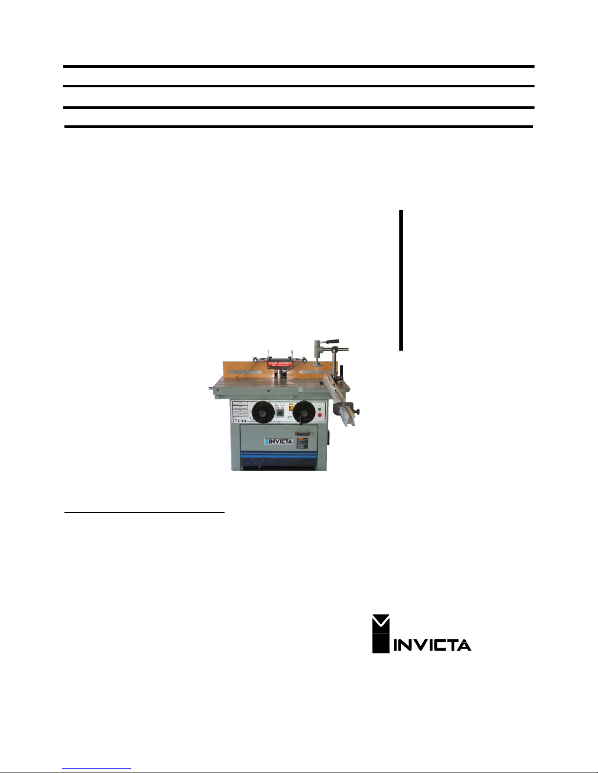
SHAPER
Model TI-14
General Instructions
As with all equipment, safety is to be a priority. The operator should understand the safety features and apply good
safety habits in transportation, adjustment, maintenance and operation of the machine. Practice and teach others
the safe operating procedures of this machine and help to prevent the possibility of accidents.
Safety Rules
1. For your own safety, read carefully the Instruction Manual before attempting to operate the machine.
2. If you are not thoroughly familiar and comfortable with the adjustment and operation of the machine, ask for
instruction from your supervisor or a fully qualified person. You may also contact Invicta USA.
3. Before the initial operation of the machine, remove all packaging, shipping grease and fully assemble the
machine. Pay special attention to the assembly of safety components.
4. Wear proper apparel while operating the machine. Never wear loose fitting clothing, gloves or ties. Always
remove rings or other jewelry before operating the machine. It is strongly suggested the operator wear
shoes with non-slip soles and also wear a protective hair net to prevent hair entanglement in moving parts.
5. Always wear personal safety equipment. Follow the safety regulations of your country and your company.
6. Have a certified person make all wiring connections to power source and properly gro und the machine.
7. Always disconnect the machine from the power source and use lockout procedures before servicing,
changing cutting tools and during any cleaning of the machine.
8. Before starting the machine, be aware that the work area is clean and free of debris. Cluttered areas are
invitations for accidents to occur. .
9. Keep the safety guard(s) of the machine in place and in proper working condition. Never operate
machinery without safety equipment in place. Report any damage to your supervisor. Keep children and
visitors a safe distance from the working area.
10. Never leave the machine running while unattended. Turn off the power source during breaks. The machine
should come to a complete stop before walking away.
11. Do not operate the machine under the influence of drugs or alcohol. Consult your physician when taking
medications.
12. Do not force the machine beyond its limitations. It will produce a nicer and safer job and at the rate it was
designed to operate.
Additional Safety Rules for the Operation of Shapers
1) Avoid Kickbacks. “Kickback” can occur when the workpiece is forced back by the cutter during improper
operation. When “Kickback” occurs an injury can result. Some of the causes of Kickback are:
A- Improper tooling
B- Knots, Nails or Imperfections in the workpiece.
C- Heavier Cuts than the machine was designed for.
D- Failure to use the material hold downs and or a powerfeeder with thin or narrow workpieces.
2) Always maintain the proper relationship of in-feed fence and the out-feed fence in relation to the Cutterhead.
3) Never start the work-piece into the cutterhead before allowing it to reach operation speed.
4) Keep the cutter sharp and free of rust and pitch
5) Never use an unbalanced cutterhead or an improper speed fo r the cutterhead.
6) Support and control the workpiece properly all times during the operation.
7) Never reverse the direction of the workpiece after beginning operation. Kickback can occur.
8) Always use the diameter spindle that is the correct size for your cutter.
9) When changing cutterheads be sure to replace the cutter guard before operation.
10) Check for proper rotation after each cutter change and the beginning of work.
11) Mounting of large diameter cutterheads should be as close to the base of the spindle as possible.
12) Keep the work area as clean as possible to avoid slipping or tripping.
13) Never place loose items on the table top while in operation.
14 Never continue to operate equipment that is in need of repair.
15) Safety glasses are strongly recommended during operation.
01

S
HAPER
Mod. TI-14
Electrical Connections of the Machine
Each machine is provided with a reference plate that
indicates the requirements of the electrical service
needed for the machine to properly operate. Before
you call a certified electrician to make the wiring
connections, be sure that the voltage and cycle
(phase) stated on this reference plate are the same
as provided in your building.
(Electrician) Remove the electrical box cover and
connect the electrical supply wires to the proper
terminals. Rapidly turn on and off the machine and
then visibly check the rotation direction of the
cutterhead. It should correspond to the direction
indicated on reversing switch. If not, proceed with the
instructions below:
For three-phase machines: invert two wires of the
power source without changing the internal
connections of the machine. See the electrical
diagrams for three-phase on page 08. If further
information is needed or contact Invicta USA.
Loading and unloading
When loading and unloading the machine there
should be no pressure on areas which could affect its
functioning. On figure 01 we show correct procedure
for handling.
Installing the Machine
Place the machine on a level and structurally sound
floor to avoid vibration. On figure 02 we display a
foundation layout for your reference.
CAUTION: The machine comes with a reverse rotation
switch, set it as shown (Clockwise) on the display in the
front panel before testing the rotation direction.
CUTTERHEAD ROTATION DIRECTION
Fig. 01
Fig. 02
0
2

S
HAPER
Technical Specification
Version
02
03
04
05
35.43 x 43.3 35.43 x 43.3 35.43 x 43.3 35.43 x 43.3
Table dimensions (in)
33.46
33.46
33.46
33.46
Working height (in)
Spindle vertical travel (in)
5.51
5.51
5.51
5.51
Morse taper
#5
#5
#5
#5
Spindle diameter (in)
.75 & 1.25 .75 & 1.25 .75 & 1.25 .75 & 1.25
Useable spindle length (in)
5.31
5.31
5.31
5.31
Table insert diameter (in)
16.53
16.53
12.99
12.99
Spindle speeds (rpm)
Three phase motor power
7.5 HP
7.5 HP
7.5 HP
7.5 HP
Sliding table travel (in)
-
-
39.37
39.37
Brake
YES
YES
YES
YES
Micro-adjustable fence
YES
YES
YES
YES
Sliding table (in)
-
-
10.82x54.13 10.82x54.13
Spindle Tilting
-
YES - YES
Net weight
1257 lbs 1257 lbs 1389 lbs 1433 lbs
Gross weight
1425 lbs 1433 lbs 1566 lbs 1621lbs
0
3
SHAPER
Changing the Spindle
INVICTA TECHNICAL BULLETIN
Subject: Correct Procedure for Changing Spindles
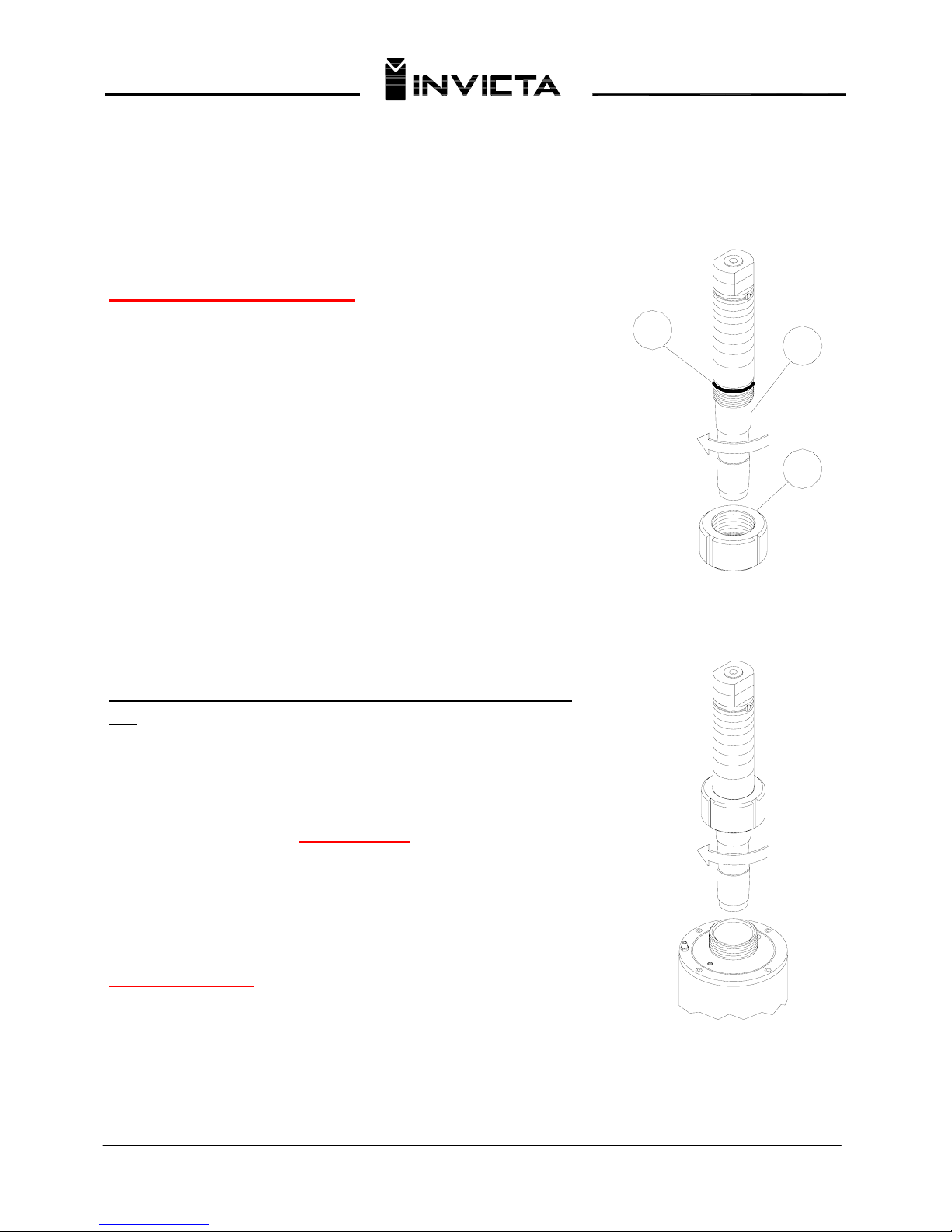
Pre-installation Instructions
Remove all cosmoline from interchangeable spindle and
mating main spindle before mounting tooling. It is very
important that the locking nut, threads and taper be
clean. Make sure O-ring is in place just below the
bottom lip of the spindle. This acts as a dust shield.
Failure to have O-ring in place will allow dust and
debris to filter down into spindle threads, making it
very difficult to remove the spindle. Lightly oil lower
spindle with 10wt oil before seating.
1. Screw the locking nut (A) up on the fine threads of
the interchangeable spindle (B) until the rubber O-ring
(C) is flush with the bottom lip of the spindle.
2. Then place the interchangeable spindle assembly into
the main spindle and tighten by turning with the nut.
IMPORTANT: Allow spindle assembly to turn with the
nut. Turn until hand tight.
3. Take the spindle nut wrench and turn nut ¼ turn
clockwise to tighten.
CAUTION!!
Do not turn the spindle separately and always return
the locking nut to contact the bottom of rubber O-ring
each time the spindle is removed.
IMPORTANT: All tooling used on the spindle
must be balanced.
C
B
A
04
SHAPER
Mod. TI-14
Accessories
1 Special wrench
1 Open end wrench 38 mm
1 Open end wrench 10 x 13 mm
1 Open end wrench 19 x 24 mm
1 Open end wrench 24 x 27 mm
1 Allen wrench 5 mm
1 Cutter Shaft(Spindle) Ø3/4” with rings
1 Cutter Shaft(Spindle) Ø1 1/4” with rings
1 Allen wrech 14 mm
1 Instruction manual
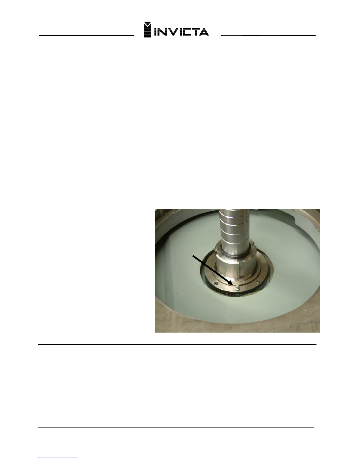
Lubrication
Your machine requires lubrication as follows:
The upper bearing should be lubricated every
48 hours of use with a high quality grease,
through point A. Below are makes and types
of greases that can be used on this bearing:
• Darina Grease nº 2 - SHELL
The lower bearing does not need
greasing as it is shielded.
Machine Identification and Replacement Parts
A
Every machine has a manufacturing code (tag) which provides the manufacturer serial number and production
date. This manual gives listing numbers of parts that form your machine. They provide description and order
numbers. When needed, use original parts; always mention the manufacturing code, part number and quantity
desired.
05

SHAPER
Mod. TI-14
Adjustment Instructions
Controls
1 – On (Green) and Off (Red) Switches 6 – Spindle lock lever
2 - Vertical Height Adjusting Handwheel 7 - Tilt Adjustment Handwheel (Ver. 3 and 5)
3 – Handwheel Lock 8 – Brake
4 – Sliding Table Lock (Ver. 4 and 5) 9 – Spindle Reversing Switch
5 - Belt tension lever
C
D
F
E
A
B
Inserting the Interchangeable Spindles (Cutter Shafts)
Fig. 3
Turn Lever nº 6 to its horizontal position locking the drive shaft.
Loosen knob nº 3 and turn handwheel nº 2 until the shaft reaches its
maximum height. Screw nut “A” onto the interchangeable spindle shaft
to be used until tightening up against rubber ring “B”. Then screw this
assembly into the drive shaft turning the nut until the assembly is
securely tightened. Finally unlock the drive shaft by lever nº 6.
IMPORTANT:
1. When assembling the nut to the spindle, face “C” should be slightly
higher than face “D”.
2. When changing spindles, the locknut face “E” should never come
in contact with surface “F”. If this occurs, change the relation of the
locknut to the shaft before tightening.
3. Never allow debris to come between shaft and the spindle housing.
4. Protect the spindle mating surfaces from damage at all times.
Fig. 4
06
SHAPER
Mod. TI-14
G
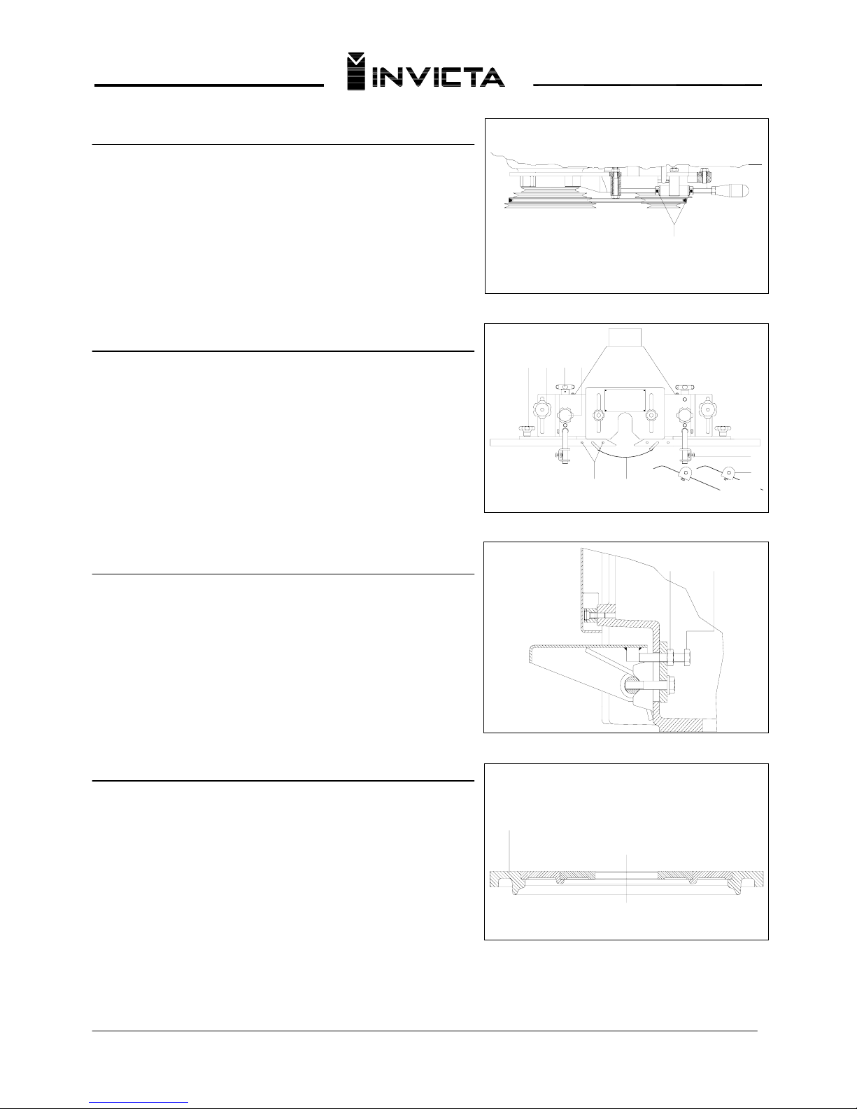
Change Speeds and Adjustment of Belt Tension
To change the spindle speed, pull lever nº 5 (fig.3 pg.6) and
loosen the belt. Change the belt position both pulleys, and tighten
the belt by returning the lever to its original position. Adjust belt
tension as belt wears by nuts “G” when necessary.
Micro -Adjustable Fence Assembly
The fence assembly is fastened directly to the table using knobs
“I” at points “R”. Fine adjustment of the infeed and outfeed fence
around the cutter is done by knobs “J”. Once adjusted, the fence
is locked in position by knobs “K”.
Note: Keep the wood guide close to the cutter.
The front and upper flexible metal spring holddown feet, “N” and
“O” should be adjusted to press the wood correctly against the
fence and the table. Top guard “M” comes with the fence and can
be positioned many different ways by holes “L”.
Brake Adjustment
When it is necessary to adjust the brake, loosen nut “P” and
adjust the steel cable by screw “Q” until the assembly is adjusted
properly. Finally, lock the screw by nut “P”.
Table Inserts
Fig. 5
J
N
O
HI K
ML
Fig. 6
P
Q
Fig. 7
R
The machine is equipped with three inserts “R”, which allow the
accomodation of various size cutters. Alignment marks on each
insert are to assure the correct positioning. The inserts can be
locked in place to avoid rotating by turning the lock with an allen
wrench. The largest diameter insert is supplied with four leveling
screws which allow it to be leveled to the table. If an adjustment
is necessary, place a straight edge on the insert and across the
table, then tighten or loosen the four leveling screws until the
correct relationship of the rings to the table is achieved.
NOTE: Cam lock nº 4 (fig.3 pag.6) must be loose when making this adjustment.
Fig. 8
07
S
HAPER
Mod. TI-14
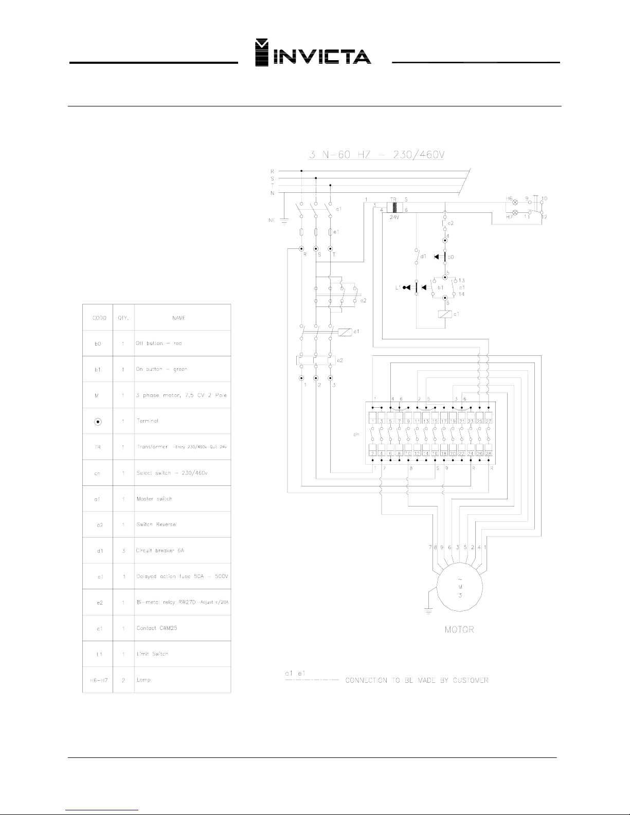
ELECTRICAL DIAGRAM
IMPORTANT
SELECT THE VOLTAGE (230/460V) OF YOUR
INTERNAL ELECTRIC NETWORK.
THE VOLTAGE SELECTION KEY IS LOCATED ON
THE ELECTRICAL BOX.
FOR YOU SAFETY THE VOLTAGE SELECTION
KEY IS ON NEUTRAL POSITION.
08
 Loading...