

Page 1

Owner's Operator And Maintenance Manual
TRACER EX
TRACER IV
R
R
HEAVY DUTY/EXTRAWIDE
TRACER TRANSPORT
INVACARE MG
R
R
DEALER: THIS MANUAL MUST BE GIVEN TO THE USER
OF THE WHEELCHAIR.
USER: BEFORE USING THIS WHEELCHAIR, READ THIS
MANUAL AND SAVE FOR FUTURE REFERENCE.
Page 2

W
A
R
N
I
N
G
WARNING
WARNING
DO NOT OPERAT E THIS EQUIPMENT WITHOUT FIRST
READING AND UNDERSTANDING THIS MANUAL. IF YOU ARE
UNABLE TO UNDERST AND THE W ARNINGS, CAUTIONS, AND
INSTRUCTIONS, CONT ACT A HEAL THCARE PROFESSIONAL,
DEALER OR TECHNICAL PERSONNEL IF APPLICABLE BEFORE
ATTEMPTING TO USE THIS EQUIPMENT - OTHERWISE INJUR Y OR
DAMAGE MAY RESUL T.
SAVE THESE INSTRUCTIONS
2
Page 3

T ABLE OF CONTENTS
TABLE OF CONTENTS
NOTE: The information in this owner's manual applies to the TRACER EX, TRACER IV, TRACER TRANSPORT
and the INVACARE MG wheelchairs except where specified.
SPECIAL NOTES ................................................ 4
SAFETY SUMMARY ........................................... 5
SAFETY/HANDLING OF WHEELCHAIRS ............ 7
SPECIFICA TIONS............................................. 12
SAFETY INSPECTION CHECKLIST ................. 13
TROUBLESHOOTING ..................................... 14
MAINTENANCE ................................................ 14
PROCEDURE 1 - FRONT RIGGINGS ............... 15
SWINGAW AY FOOTREST ASSEMBL Y
INST ALLATION................................................. 15
SWINGAW AY FOOTREST HEIGHT
ADJUSTMENT ................................................. 1 5
HEEL LOOP REPLACEMENT ............................ 15
ELEV ATING LEGREST ASSEMBL Y
INST ALLATION................................................. 16
ADJUSTING THE ELEV ATING LEGREST
ASSEMBL Y ..................................................... 1 6
PROCEDURE 2 - ARMS.................................... 17
REMOVING OR REPLACING ST ANDARD
ARMREST....................................................... 17
ADJUSTING ARMREST HEIGHT - ADJUST ABLE
HEIGHT ARMS ONL Y ....................................... 17
USING OR REPLACING FLIP-BACK ARMREST .. 17
PROCEDURE 3 - SEA T AND BACK .................. 18
FOLD DOWN BACK - TRACER TRANSPORT
ONLY .............................................................. 18
REPLACING BACK UPHOLSTERY..................... 1 8
REPLACING THE SEA T UPHOLSTERY .............. 18
ADJUSTING SEA T WIDTH .................................. 18
PROCEDURE 4 - REAR WHEELS..................... 20
REMOVING/INST ALLING THE REAR WHEELS.... 2 0
REPLACING REAR WHEEL HANDRIM ............... 20
REPLACING/REP AIRING REAR WHEEL
TIRE/TUBE...................................................... 20
PROCEDURE 5 - FRONT CASTERS ................ 21
INST ALLING/REPLACING SIX OR EIGHT-INCH
FRONT CASTERS AND FORKS...................... 21
ADJUSTING FRONT CASTERS ......................... 21
REPLACING/REP AIRING FRONT CASTER
TIRE/TUBE...................................................... 21
REPLACING FRONT CASTERS......................... 2 1
PROCEDURE 6 - SEAT-TO-FLOOR HEIGHTS . 22
CHANGING SEA T-TO-FLOOR HEIGHT-
TRACER EX ONL Y .......................................... 22
PROCEDURE 7 - ANTI-TIPPERS/WHEEL LOCKS
23
INST ALLING ANTI-TIPPERS ................................ 23
WHEEL LOCK ADJUSTMENT ............................ 24
PROCEDURE 8 - OPTIONS.............................. 25
INST ALLING AMPUTEE ATT ACHMENT ................ 2 5
INST ALLING FIXED HEIGHT I.V. ROD .................. 25
INST ALLING THE CARRYING POCKET ............... 2 5
INST ALLING THE SEAT POSITIONING STRAP .... 2 6
INST ALLING/ADJUSTING THE FRONT
ANTI-TIPPERS................................................ 2 6
INST ALLING THE TELESCOPING I.V . ROD ......... 28
WARRANTY ...................................................... 31
T
A
B
L
E
O
F
C
O
N
T
E
N
T
S
3
Page 4

SPECIAL NOTES
SPECIAL NOTES
S
P
E
C
A
L
N
O
T
E
S
WARNING/CAUTION notices as used in this manual apply to hazards or unsafe practices which could
result in personal injury or property damage.
NOTICE
I
THE INFORMATION CONT AINED IN THIS DOCUMENT IS SUBJECT TO CHANGE WITHOUT NOTICE.
WHEELCAIR USER
As a manufacturer of wheelchairs, Invacare endeavors to supply a wide variety of wheelchairs to
meet many needs of the end user . However , final selection of the type of wheelchair to be used by an
individual rests solely with the user and his/her healthcare professional capable of making such a
selection.
WHEELCHAIR TIE-DOWN RESTRAINTS AND SEA T POSITIONING STRAPS
Invacare recommends that wheelchair users NOT be transported in vehicles of any kind while in wheel-
chairs. As of this date, the Department of Transportation has not approved any tie-down systems for
transportation of a user while in a wheelchair, in a moving vehicle of any type.
It is Invacare’s position that users of wheelchairs should be transferred into appropriate seating in vehicles for transportation and use be made of the restraints made available by the auto industry. Invacare cannot and does not recommend any wheelchair transportation systems.
AS REGARDS RESTRAINTS - SEA T POSITIONING STRAPS - IT IS THE OBLIGATION OF THE DME DEALER, THERAPISTS AND OTHER HEALTHCARE PROFESSIONALS TO DETERMINE IF A SEA TPOSITIONING STRAP IS REQUIRED
TO ENSURE THE SAFE OPERATION OF THIS EQUIPMENT BY THE USER. SERIOUS INJURY CAN OCCUR IN THE
EVENT OF A F ALL FROM A WHEELCHAIR.
4
Page 5

SAFETY SUMMARY
SAFETY SUMMARY
OPERATING INFORMATION
WARNING
T o determine and establish your particular safety limits, practice bending, reaching and transferring activities in several combinations in the presence of a qualified health professional BEFORE
attempting active use of the wheelchair.
DO NOT attempt to reach objects if you have to move forward in the seat.
S
A
F
E
T
Y
DO NOT attempt to reach objects if you have to pick them up from the floor by reaching down
between your knees.
DO NOT lean over the top of the back upholstery to reach objects from behind as this may cause
the wheelchair to tip over.
DO NOT shift your weight or sitting position toward the direction you are reaching as the wheelchair may tip over.
DO NOT tilt the wheelchair without assistance.
DO NOT use an escalator to move a wheelchair between floors. Serious bodily injury may occur .
DO NOT attempt to stop a moving wheelchair with the wheel locks. WHEEL LOCKS ARE NOT
BRAKES.
Before attempting to transfer in or out of the wheelchair, every precaution should be taken to
reduce the gap distance. Turn both casters toward the object you are transferring onto. When
transferring to and from the wheelchair, ALWAYS ENGAGE BOTH WHEEL LOCKS.
DO NOT operate on roads, streets or highways.
DO NOT climb, go up or down ramps or traverse slopes greater than 9
DO NOT attempt to move up or down an incline with a water, ice or oil film.
DO NOT attempt to ride over curbs or obstacles. Doing so may cause your wheelchair to tip over
and cause bodily harm or damage to the wheelchair.
o
.
S
U
M
M
A
R
Y
DO NOT use accessories, or adapters other than those authorized by Invacare.
DO NOT overtighten hardware attaching to the frame. This could cause damage to the frame tubing.
Keep hands and fingers clear of moving parts to avoid injury.
DO NOT attempt to lift the wheelchair by any removable (detachable) parts. Lifting by means of
any removable (detachable) parts of a wheelchair may result in injury to the user or damage to
the wheelchair.
DO NOT stand on the frame of the wheelchair.
Anti-tippers MUST BE attached at all times. Inasmuch as the anti-tippers are an option on this
wheelchair (You may order with or without the anti-tippers), Invacare strongly recommends ordering the anti-tippers as an additional safeguard for the wheelchair user.
When changing the seat-to-floor height you must adjust the anti-tippers accordingly.
DO NOT use the footplate as a platform when getting in or out of the wheelchair .
ALW AYS wear your SEA T POSITIONING STRAP. Inasmuch as the SEA T POSITIONING STRAP is an option on
this wheelchair (Y ou may order with or without the SEA T POSITIONING STRAP), Invacare s trongly recommends ordering the SEAT POSITIONING STRAP as an additional safeguard for the wheelchair user .
5
Page 6

SAFETY SUMMARY
S
A
F
E
T
Y
TIRE PRESSURE
DO NOT use your wheelchair unless it has the proper tire pressure (p.s.i.). DO NOT overinflate the
tires. Failure to follow these suggestions may cause the tire to explode and cause bodily harm.
Replacement of a pneumatic tire or tube MUST be performed by an authorized Invacare Dealer
or Qualified Technician.
SAFETY SUMMARY
WARNING
S
U
M
M
A
R
Y
WEIGHT TRAINING
Invacare DOES NOT recommend the use of its wheelchairs as a weight training apparatus. In-
vacare wheelchairs have NOT been designed or tested as a seat for any kind of weight training.
If occupant uses said wheelchair as a weight training apparatus, INVACARE SHALL NOT BE LIABLE
FOR BODILY INJURY AND THE WARRANTY WILL BE VOID.
WEIGHT LIMITATION
The TRACER EX, TRACER TRANSPORT and INVACARE MG wheelchairs have a weight limitation of
250 lbs. The TRACER IV EXTRA WIDE wheelchair has a weight limitation of 350 lbs. The TRACER IV
HEAVY DUTY has a weight limitation of 450 lbs. with the heavy duty option.
6
Page 7

SAFETY/HANDLING
SAFETY/HANDLING OF WHEELCHAIRS
“Safety and Handling” of the wheelchair requires the close
attention of the wheelchair user as well as the assistant. This
manual points out the most common procedures and techniques involved in the safe operation and maintenance of
the wheelchair. It is important to practice and master these
safe techniques until you are comfortable in maneuvering
around the frequently encountered architectural barriers.
Use this information only as a “basic” guide. The techniques
that are discussed on the following pages have been used
successfully by many .
Individual wheelchair users often develop skills to deal with
daily living activities that may differ from those described in
this manual. Invacare recognizes and encourages each individual to try what works best for him/her in overcoming
architectural obstacles that they may encounter, however
ALL WARNINGS and CAUTIONS given in this manual
MUST be followed. T echniques in this manual are a starting
point for the new wheelchair user and assistant with “safety”
as the most important consideration for all.
STABILITY AND BALANCE
WARNING
ALWA YS wear your seat positioning strap. Inasmuch
as the SEA T POSITIONING STRAP is an option on this
wheelchair (Y ou may order with or without the Seat
Positioning Strap), Invacare strongly recommends
ordering the Seat Positioning Strap as an additional
safeguard for the wheelchair user.
T o assure stability and proper operation of your wheelchair,
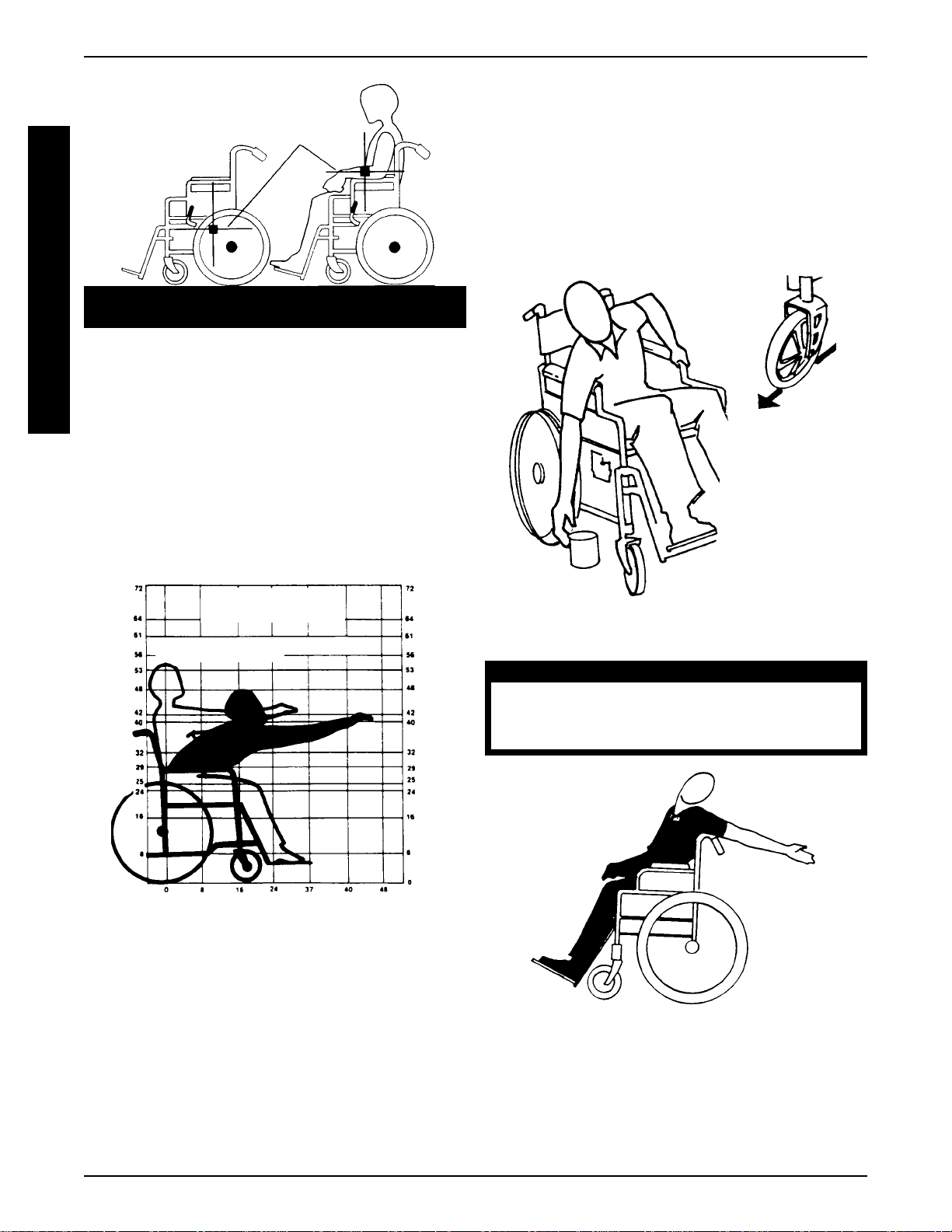
you must at all times maintain proper balance. Y our wheelchair has been designed to remain upright and stable during normal daily activities as long as you do not move beyond the center of gravity .
Virtually all activities which involve movement in the wheelchair have an effect on the center of gravity . Invacare recommends using seat/chest positioning straps for additional
safety while involved in activities that shift your weight.
DO NOT lean forward out of the wheelchair any further
than the length of the armrests. Make sure the casters are
pointing in the forward position whenever you lean forward.
This can be achieved by advancing the wheelchair and
then reversing it in a straight line.
COPING WITH EVERYDAY
OBSTACLES
Coping with the irritation of everyday obstacles can be
alleviated somewhat by learning how to manage your
wheelchair. Keep in mind your center of gravity to maintain stability and balance.
A NOTE TO WHEELCHAIR
ASSISTANTS
When assistance to the wheelchair user is required, remember to use good body mechanics. Keep your back
straight and bend your knees whenever tipping the wheelchair or traversing curbs, or other impediments.
WARNING
DO NOT attempt to lift the wheelchair by any removable (detachable) parts. Lifting by means of
any removable (detachable) parts of a wheelchair
may result in injury to the user or damage to the
wheelchair.
Also, be aware of detachable parts such as armrests or
legrests. These must NEVER be used for hand-held or
lifting supports, as they may be inadvertently released,
resulting in possible injury to the user and/or assistant(s).
When learning a new assistance technique, have an experienced assistant help you before attempting it alone.
PERCENTAGE OF WEIGHT
DISTRIBUTION
WARNING
DO NOT attempt to reach objects if you have to
move forward in the seat or pick them up from
the floor by reaching down between your knees.
Many activities require the wheelchair owner to reach,
bend and transfer in and out of the wheelchair. These
movements will cause a change to the normal balance,
the center of gravity, and the weight distribution of the
wheelchair. To determine and establish your particular
safety limits, practice bending, reaching and transferring
activities in several combinations in the presence of a
qualified healthcare professional BEFORE attempting
active use of the wheelchair.
S
A
F
E
T
Y
&
H
A
N
D
L
I
N
G
Proper positioning is essential for your safety. When
reaching, leaning, or bending forward, it is important
to use the front casters as a tool to maintain stability
and balance.
7
Page 8
SAFETY/HANDLING
CENTER OF
S
A
F
E
T
Y
&
H
A
N
D
L
N
G
Example 46% 54% 103 lbs. 130 lbs.
UNOCCUPIED OCCUPIED
I
FUNCTIONAL REACH FROM A
GRAVITY
WHEELCHAIR
The approximate reach-limit values shown in the accompanying graph were derived on the basis of a
sample of 91 male and 36 female wheelchair users.
Note the difference between the maximum and the
comfortable reach limits, a subjective but important
consideration in design.
REACHING, LEANING AND
BENDING - FORWARD
Position the front casters so that they are extended as
far forward as possible and engage wheel locks. DO
NOT A TTEMPT TO REACH OBJECTS IF YOU HA VE
TO MOVE FORW ARD IN THE SEA T OR PICK THEM
UP FROM THE FLOOR BY REACHING DOWN
BETWEEN YOUR KNEES.
FORWARD REACH
(ADUL T)
COMFORT ABLE MAXIMUM
INCHES
REACHING, LEANING - BACKWARDS
WARNING
DO NOT lean over the top of the back upholstery. This will change your center of gravity
INCHES
and may cause you to tip over.
Position wheelchair as close as possible to the desired object. Point front casters forward to create the
longest possible wheelbase. Reach back only as far
as your arm will extend without changing your sitting
position.
8
Page 9
SAFETY/HANDLING
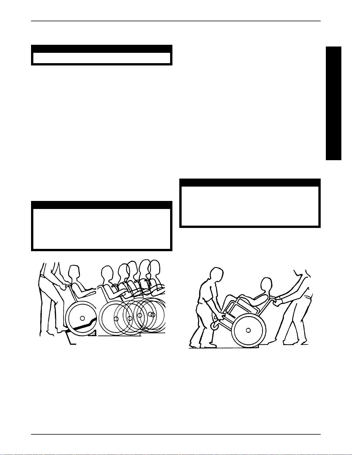
TIPPING
WARNING
DO NOT tip the wheelchair without assistance.
When tipping the wheelchair, an assistant should grasp
the back of the wheelchair on a non-removable (nondetachable) part. Inform the wheelchair occupant before tipping the wheelchair and remind him/her to lean
back. Be sure the occupant’s feet and hands are clear
of all wheels.
After mastering the techniques of tipping the wheelchair, use one (1) of the following methods to tackle
curbs, short stairs, etc.
Tipping - Curbs: Method 1 - Wheelchair With
Step Tubes
Apply a continuous downward motion until the balance point is achieved and the front casters clear the
curb. At this point, the assistant will feel a difference in
the weight distribution.
WARNING
When lowering the front casters of the wheelchair, DO NOT let the wheelchair drop the last
few inches to the ground. This could result in injury to the occupant and/or damage to the
wheelchair.
Tipping - Curbs: Method 1 - Wheelchair
Without Step Tubes
This method requires two (2) assistants. The second
assistant should be positioned at the front of the wheelchair lifting upward on a non-removable (non-detachable) part of the wheelchair frame when lifting the
wheelchair and stabilizing the wheelchair when the
wheelchair is being lowered to the ground.
The first assistant should stand on the sidewalk and
turn the wheelchair so that the rear wheels are against
the curb. Turn the anti-tippers so the anti-tip wheels
are pointing up, The wheelchair should be tilted back
to the balance point and, in one continuous upward
movement, the rear wheels should be pulled up and
over the curb. DO NOT return the front casters to the
ground until the wheelchair has been pulled backward
far enough for the front casters to clear the edge of
the curb.
WARNING
When lowering the front casters of the wheelchair, DO NOT let the wheelchair drop the last
few inches to the ground. This could result in injury to the occupant and/or damage to the
wheelchair.
Roll the wheelchair backward and SLOWL Y lower the
wheelchair in one continuous movement. DO NOT let
the wheelchair drop the last few inches to the ground.
This could result in injury to the occupant.
S
A
F
E
T
Y
&
H
A
N
D
L
I
N
G
Step Tube
METHOD 1 - WHEELCHAIR WITH STEP TUBE
Roll the wheelchair forward and slowly lower the front
of the wheelchair in one continuous movement onto
the sidewalk. Do not let the wheelchair drop the last
few inches to the ground. This could result in injury to
the occupant. Push the wheelchair forward until the
rear wheels roll up and over the curb.
METHOD 2 - WHEELCHAIR WITHOUT STEP TUBE
9
Page 10
SAFETY/HANDLING
STAIRWAYS
S
A
F
E
T
Y
&
H
A
N
D
L
I
N
G
ALWA YS wear your seat positioning strap. Inasmuch
as the SEA T POSITIONING STRAP is an option on this
wheelchair (Y ou may order with or without the Seat
Positioning Strap), Invacare strongly recommends
ordering the Seat Positioning Strap as an additional
safeguard for the wheelchair user.
Do not attempt to lift a wheelchair by lifting
on any removable (detachable) parts. Lifting
by means of any removable (detachable)
parts of a wheelchair may result in injury to the
user or damage to the wheelchair.
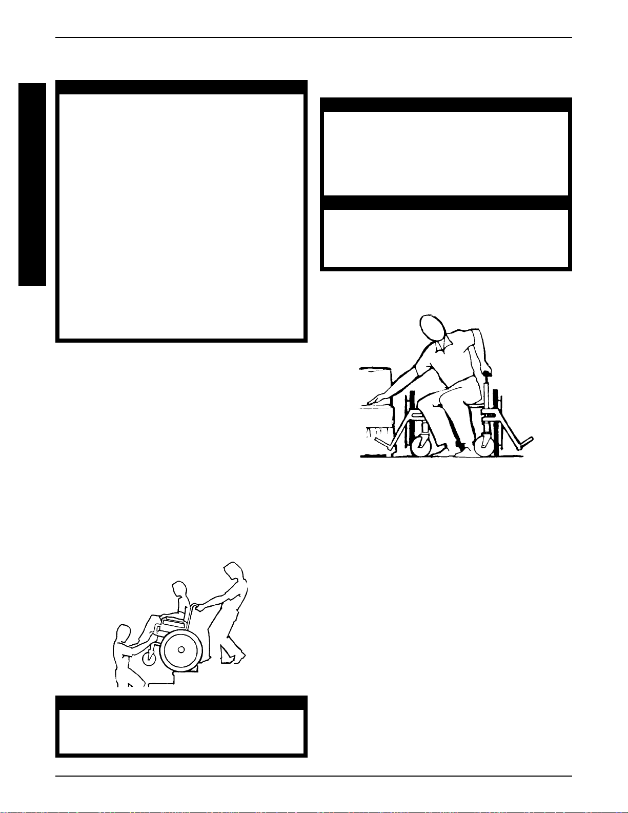
Extreme caution is advised when it is necessary to move an occupied wheelchair up or
down the stairs. Invacare recommends using
two (2) assistants and making thorough preparations. Make sure to use ONLY secure, nondetachable parts for hand-held supports.
Follow this procedure for moving the wheelchair between floors when an elevator is NOT available:
WARNING
TRANSFERRING TO AND FROM
OTHER SEATS
WARNING
BEFORE attempting to transfer in or out of the
wheelchair , every precaution should be taken
to reduce the gap distance. Tu rn both casters
toward the object you are transferring onto.
Also be certain the wheel locks are engaged
to help prevent the wheels from moving.
CAUTION
When transferring, position yourself as far back
as possible in the seat. This will help prevent
broken screws, damaged upholstery and the
possibility of the wheelchair tipping forward.
NOTE: This activity may be performed independently
provided you have adequate mobility and upper body
strength.
1. After the wheelchair has been tilted back to the
balance point, one assistant (in the rear) backs
the wheelchair up against the first step, while securely grasping a non-removable (non-detachable) part of the wheelchair for leverage.
2. The second assistant, with a firm hold on a nondetachable part of the framework, lifts the wheelchair up and over the stair and steadies the wheelchair as the first assistant places one (1) foot on
the next stair and repeats STEP 1.
3. The wheelchair should not be lowered until the last
stair has been negotiated and the wheelchair has
been rolled away from the stairway.
Position the wheelchair as close as possible along side
the seat to which you are transferring, with the front
casters pointing toward it. Engage wheel locks. Shift
body weight into seat with transfer.
During independent transfer, little or no seat platform will
be beneath you. Use a transfer board if at all possible.
ESCALATORS? SORRY !
DO NOT use an escalator to move a wheelchair between floors. Serious bodily injury may
occur .
10
Page 11
SAFETY/HANDLING
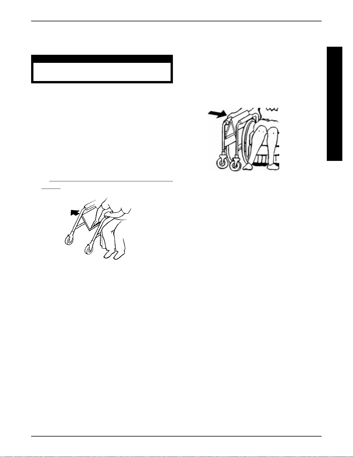
FOLDING AND UNFOLDING THE
WHEELCHAIR
WARNING
Keep hands and fingers clear of moving parts
to avoid injury.
Opening
1. Open the wheelchair by grasping the push handle
of the wheelchair closest to you.
2. Tilt the wheelchair towards you (raising the
opposite wheel and caster off the ground/floor).
3. Push downward on the TOP of the seat rail closest
to you where the seat upholstery is attached until
the wheelchair is fully open.
4. Engage both wheel locks, open the footrest/legrest
for clearance and transfer into the wheelchair. Refer
TRANSFERRING TO AND FROM OTHER
to
SEATS in this section of the manual.
Closing
1. Swing footrest/legrest in locked position to the front
of the wheelchair.
2. Pivot footplates upward to vertical position.
3. With both hands, grasp the middle of the seat upholstery at the front and back edge and lift up.
NOTE: If wheelchair is equipped with carry straps, the
wheelchair may be closed by pulling up on the straps.
"HAMMOCK OR SLING SEA T" MODELS
S
A
F
E
T
Y
&
H
A
N
D
L
I
N
G
"HAMMOCK OR SLING SEA T" MODELS
11
Page 12

SPECIFICATIONS
S
P
E
C
I
F
I
C
A
T
I
O
N
S
Seat Width:
Seat Depth:
Overall Width:
Permanent Arm:
Removable Arm:
Overall Depth
(w/o riggings):
Seat-to-Floor:
Back Style:
Back Height:
Arm Styles:
SPECIFICATIONS
TRACER IV
20, 22 and 24-inches
18-inches
N/A
27-1/2 to 31-1/2-inches
32-inches
21-inches
Fixed
16-inches
Fixed-Desk/Full Length
Adjustable Height Desk/Full Length
TRACER TRANSPORT
14,16,18 and 20-inches
16-inches
18-1/2 to 22-1/2-inches
19 to 25 inches
27-inches
21-inches
Fixed and Fold Down
16-inches
Permanent,
Fixed-Desk/Full Length
INVACARE MG
16-1/2 and 18-inches
16-inches
23-1/4 and 24-3/4 inches
24-1/2 and 26-inches
32-1/2-inches
21-inches
Fixed
16-inches
Permanent or Remov-
able Fixed Height Desk/
Full Length
TRACER EX
16-1/2, 18 and 20-inches
16-inches
23-1/4 and 24-3/4-inches
24-1/2, 26, and 28-inches
32-1/2-inches
21-inches
Fixed
16-inches
Permanent, Fixed-Desk/
Full Length
Front Riggings:
Rear Axle:
Rear Wheels:
Handrims:
Wheel Locks:
Caster Size:
Upholstery:
Swingaway Footrest/Elevating Legrest, Articulating Elevating Legrest
Permanent
24-inch Composite; DTM,
Pneumatic-Flat Free Insert
-(24-inch Composite
DTM Standard)
Chrome
Push to Lock
8 x 1-inch Solid Rubber
(Standard), 8 x 1-3/4-inch
Semi-Pneumatic
Vinyl - dark blue (stan-
dard), Marina Blue,
Space Blue, Dove Grey,
Ruby, and Camel
Swingaway Footrest,
Elevating Legrest
Permanent
8x1-inch Solid Rubber
(Standard),8x1-1/4-inch
Composite Urethane
N/A
Push to Lock
8 x 1-inch Solid Rubber
(Standard) 8 x 1-1/4-inch
Composite Urethane
Vinyl - Lightweight Black
(Standard), Navy Blue,
Blue Topaz or Claret
Naughahyde and Navy
Textilene
Hook On Elevating
Legrest, Swingaway Footrest and Elevating Legrest
Permanent
24-inch Composite - Urethane Tire
Composite
Push to Lock
8 x 1-inch Solid Rubber Dark Grey
Silver Blue Vinyl
Swingaway Footrest,
Elevating Legrest,
Padded Elevating Legrest
Permanent
20, 22, 24-inch Compos-
ite; Urethane,Pneumatic, or
Pneumatic Flat Free Insert- (24-inch Composite
Urethane Standard)
Composite (Standard),
Chrome, or Aluminum
Push to Lock
8 x1-inch Solid Rubber -
Dark Grey (Standard)
8 x1-inch Solid Rubber
- Light Grey, 8 x1-1/4inch
Pneumatic or Pneumatic
Flat Free, 8x1-3/4-inch
Semi Pneumatic, 8x2inch Pnumatic, 6x1-inch
Urethane - Light Grey , or
Dark Grey
Midnight Blue (Stan-
dard), Ruby
Weight (approx)*:
Permanent Arm:
Removable Arm:
Shipping Weight
(approx.)*:
Permanent Arm:
Removable Arm:
N/A
52 lbs. (22" Wide)
N/A
62 lbs.
26 lbs.
31 lbs.
30 lbs.
35 lbs.
35 lbs. (36-1/2 lbs. for Fixed
Front End)
38 lbs.
44-1/2 lbs. (46 lbs. for
Fixed Front End)
47-1/2 lbs.
35 lbs.
38 lbs.
44 1/2 lbs.
47 1/2 lbs.
*Weights based on 18-inch wide chair without front rigging. All weights are approximate and will vary depending on
how wheelchair is equipped.
12
Page 13

SAFETY INSPECTION CHECK LIST
SAFETY INSPECTION CHECKLIST
NOTE: Every six (6) months take your wheelchair to a qualified dealer for a thorough inspection and servicing. Regular cleaning
will reveal loose or worn parts and enhance the smooth operation of your wheelchair. To operate properly and safely, your
wheelchair must be cared for just like any other vehicle. Routine maintenance will extend the life and efficiency of your wheelchair.
Initial adjustments should be made to suit personal body structure/preference. Thereafter follow these maintenance procedures:
ITEM
GENERAL
● Wheelchair rolls straight (no excessive drag or pull to one side).
SEA T AND BACK (PROCEDURE 3)
● Inspect for rips or sagging.
● Inspect for loose or broken hardware.
REAR WHEELS (PROCEDURE 4)
● No excessive side movement or binding when lifted and spun.
HANDRIMS (PROCEDURE 4)
● Inspect for signs of rough edges or peeling.
SPOKES
● Inspect for broken spokes.
FRONT CASTER (PROCEDURE 5)
● Inspect wheel/fork assembly for proper tension by spinning caster;
caster should come to a gradual stop.
● Loosen/tighten locknut if wheel wobbles noticeably or binds to a stop.
INITIALL Y
X
X
X
X
X
X
X
X
INSPECT/
ADJUST
WEEKL Y
X
X
X
INSPECT/
ADJUST
MONTHL Y
X
X
INSPECT/
ADJUST
PERIODICALL Y
X
X
X
X
S
A
F
E
T
Y
I
N
S
P
E
C
T
I
O
N
● Wheel bearings are clean and free of moisture.
CAUTION: As with any vehicle, the wheels and tires should be
checked periodically for cracks and wear, and should be replaced.
TIRES
● Inspect for flat spots and wear.
If pneumatic tires, check for proper inflation.
●
CAUTION: As with any vehicle, the wheels and tires should be
checked periodically for cracks and wear, and should be replaced.
WHEEL LOCKS (PROCEDURE 7)
● Do not interfere with tires when rolling.
● Pivot points free of wear and looseness.
● Wheel locks easy to engage.
CLEANING
● Clean upholstery and armrests.
X
X
X
X
X
X
X
X
X
X
X
X
X
X
13
Page 14

TROUBLESHOOTING/MAINTENANCE
TROUBLESHOOTING
CHAIR VEERS
T
R
O
U
B
L
E
S
H
O
O
T
I
N
G
LEFT/RIGHT
X
X
X
MAINTENANCE SAFETY
SLUGGISH TURN/
PERFORMANCE
X
X
CASTERS
FLUTTER
X
X
X
MAINTENANCE
PRECAUTIONS
WARNING
After ANY adjustments, repair or service
and BEFORE use, make sure all attaching hardware is tightened securely - otherwise injury or damage may result.
CAUTION
DO NOT overtighten hardware attaching
to the frame. This could cause damage
to the frame tubing.
SUGGESTED MAINTENANCE
PROCEDURES
M
A
1. Before using your Tracer Series wheelchair , make sure
I
N
T
E
N
A
N
C
E
all nuts and bolts are tight. Check all parts for damage or
wear and replace. Check all parts for proper adjustment.
SQUEAKS AND
RATTLES
X
LOOSENESS
IN CHAIR
X
CHAIR 3
WHEELS
X
SOLUTIONS
If pneumatic, check tires for correct and equal pressure.
Check for loose stem nuts/bolts.
Check that both casters contact
ground at the same time.
WARNING
DO NOT use the wheelchair unless it has
the proper tire pressure (p.s.i.). DO NOT
overinflate the tires. Failure to follow these
suggestions may cause the tire to explode
and cause bodily harm.
2. If tires are pneumatic, recommended tire pressure is
listed on the side wall of the tire.
3. The wheels and tires should be checked periodically
for cracks and wear, and should be replaced when
necessary by your authorized dealer or by a qualified
technician.
4. Periodically check handrims to ensure they are securely attached to the rear wheels. Refer to
ING REAR WHEEL HANDRIM in PROCEDURE 4
of this manual.
5. Periodically adjust wheel locks in correlation to tire
wear. Refer to
WHEEL LOCK ADJUSTMENT in
PROCEDURE 7 of this manual.
6. Periodically check front caster and rear wheel hubs
to make sure they are clean.
7. Check Upholstery for sagging, rips or tears.
REPLAC-
14
Page 15

FRONT RIGGINGS
PROCEDURE 1
This Procedure includes the following:
Swingaway Footrest Assembly Installation
Swingaway Footrest Height Adjustment
Heel Loop Replacement
Elevating Legrest Assembly Installation
Adjusting the Elevating Legrest Assembly
WARNING
After ANY adjustments, repair or service and
BEFORE use, make sure all attaching hardware
is tightened securely - otherwise injury or damage may result.
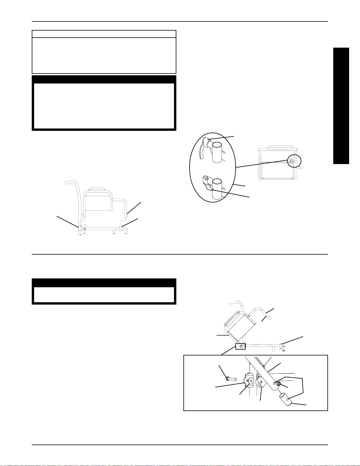
SWINGAWAY FOOTREST ASSEMBLY
INSTALLATION (FIGURE 1)
1. Turn the footrest to the side (open footplate is perpendicular to wheelchair).
2. Install the hinge plates on the footrest onto the hinge
pins on the wheelchair frame.
3. Push the footrest towards the inside of the wheelchair until it locks into place.
SWINGAWAY FOOTREST HEIGHT
ADJUSTMENT (FIGURE 2)
NOTE: Release the footrest locking mechanism and lift
the footrest off of the hinge pins. Lay the assembly on a
flat surface to simplify this procedure.
1. Remove impact guards and/or calf strap, if necessary .
2. Loosen, but do not remove the bolt and locknut that
secure the lower footrest assembly to the upper footrest support.
3. Reposition the lower footrest assembly to the desired
height.
4. Securely tighten the bolt and locknut.
5. Repeat this procedure for the other footrest, if necessary .
6. Replace impact guards and/or calf strap, if necessary .
Upper
Footrest
Support
Bolt and
Locknut
Lower
Footrest
Assembly
F
R
O
N
T
R
I
G
G
I
N
G
S
NOTE: The footplate will be on the inside of the wheelchair when locked in place.
4. Repeat this procedure for the other footrest assembly .
5. To release the footrest, push the footrest release lever inward, rotate footrest outward.
Hinge Plate
Hinge Pins
Hinge
Plate
Footrest
Release
Lever
Swingaway
Footrest
Assembly
FIGURE 1 - SWINGA W AY FOOTREST
ASSEMBLY INSTALLATION
FIGURE 2 - SWINGAWAY FOOTREST HEIGHT
ADJUSTMENT
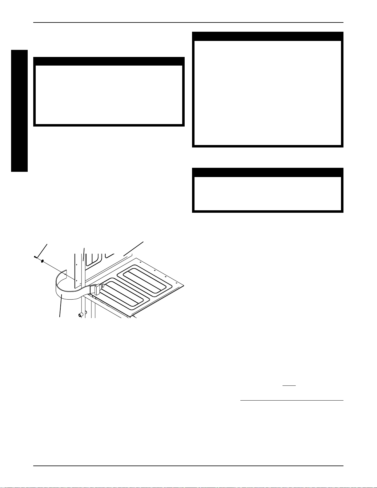
HEEL LOOP REPLACEMENT
(FIGURE 3)
NOTE: Heel loops are not available on Invacare MG
wheelchairs.
1. Loosen, but do not remove the bolt and locknut that
secure the lower half of the footrest to the swingaway
footrest assembly.
2. Remove the lower footrest assembly.
3. Remove the phillips screw and locknut that secure
the heel loop to the footrest.
4. Slide heel loop over cane of the footrest assembly.
5. Replace heel loop.
6. Reverse STEPS 1-5 to reassemble.
NOTE: When securing the heel loop to the footrest assembly, tighten the phillips screw and locknut until the
spacer is secure.
15
Page 16

PROCEDURE 1 FRONT RIGGINGS
Phillips Screw
F
R
O
N
T
R
I
G
G
I
N
ELEVATING LEGREST ASSEMBLY
G
INSTALLATION (FIGURE 4)
S
1. Place legrest assembly on the outside of the wheel-
2. Rotate legrest assembly toward the inside of the
Spacer
Locknut
FIGURE 3 - HEEL LOOP REPLACEMENT
chair and install the hinge plates onto the hinge pins
on wheelchair frame (FIGURE 4).
wheelchair until it locks in place (FIGURE 4).
Bolt and Locknut
Heel Loop
Slide T ube
Footplate
6. To release the legrest, push the legrest release
handle toward the inside of the wheelchair
(facing the front of the wheelchair) and swing the
legrest assembly to the outside of the wheelchair.
ADJUSTING THE ELEVATING
LEGREST ASSEMBLY (FIGURE 5)
NOTE: Adjustments to Articulating Legrests and Fixed
Front End Legrests are performed in the same fasion as
the elevating legrest.
1. To adjust the elevating legrest, raise legs until the
desired height is obtained.
2. To reposition legrest to normal position, support leg
with one (1) hand and push release lever downward
with other hand.
3. To adjust the calfpad, turn pad towards the outside of
the wheelchair.
4. Slide the calfpad up or down until the desired position
is obtained.
NOTE: The footplate will be on the inside of the wheelchair when locked in place.
3. Repeat this procedure for other legrest assembly.
4. After seated in wheelchair, adjust footrest to correct height by loosening the locknut and
sliding the lower footrest assembly tube up or
down until desired height is achieved.
5. Tighten locknut securely.
Legrest Release Handle
Hinge Pins
Hinge
Plates
Bolt and
Locknut
Footrest
Assembly
Calfpad
Assembly
Footplate
Lower
5. To secure the calfpad, turn the calfpad towards the
inside of the wheelchair.
Release Lever
Calfpad Rotated for
Height Adjustment
Calfpad
FIGURE 5 - ADJUSTING THE ELEVATING LEGREST
ASSEMBL Y
FIGURE 4 - ELEVATING LEGREST INST ALLATION
16
Page 17
ARMS PROCEDURE 2
This Procedure Includes the Following:
Removing or Replacing Standard Armrest
Adjusting Armrest Height - Adjustable
Height Arms Only
Using or Replacing Flip-Back Armrest
WARNING
After ANY adjustments, repair or service and BEFORE use, make sure all attaching hardware is
tightened securely - otherwise injury or damage
may result.
Make sure the armrest is securely locked into the
arm socket BEFORE using the wheelchair.
REMOVING OR REPLACING
STANDARD ARMREST (FIGURE 1)
1. Press in armrest release button located on armrest.
2. Pull straight up to remove armrest from arm sockets.
3. Replace armrest by reversing STEPS 1-2.
Armrest Release
Button
Arm Socket
Arm Socket
ADJUSTING ARMREST HEIGHT ADJUSTABLE HEIGHT ARMS ONLY
(FIGURE 2)
1. Unlock the armrest by flipping the height adjustment
lever on the top front of the armrest to the UP (HORI-
ZONT AL) position.
2. Adjust armrest to desired height.
NOTE: Height adjustment lever MUST be in the unlocked
position when placing armrest into the arm assembly.
3. Lock the armrest by pressing the height adjustment
lever into the DOWN (VERTICAL) position when the
desired armrest height is achieved.
Locked (Vertical)
Height Adjustment Lever
Unlocked (Horizontal)
FIGURE 2 - ADJUSTING ARMREST HEIGHT -
ADJUST ABLE HEIGHT ARMS ONL Y
A
R
M
S
FIGURE 1 - REMOVING OR REPLACING
ST ANDARD ARMREST
USING OR REPLACING FLIP-BACK
ARMREST (FIGURE 3)
WARNING
DO NOT operate or replace flip-back armrest
when wheelchair is folded.
Using
1. Press in armrest release button located on armrest
front tube.
2. Rotate front of armrest UP and BACK and out of
arm socket.
3. Reverse STEP 2 to replace armrest to DOWN position.
4. Position the front of the armrest into the arm socket.
5. Ensure armrest is securely locked into arm socket
and snap button locks into place BEFORE using.
Replacing
1. Perform STEPS 1-2 above to flip the armrest back.
2. Remove bolt, washer, spacer and locknut securing
armrest to wheelchair frame.
3. Remove armrest from frame.
4. Position new insert into new rear armrest tube, aligning the mounting holes.
5. Insert the new bolt through the armrest mounting
bracket, new washer, new spacer and new armrest
rear tube, as shown in FIGURE 3.
NOTE: Ensure the spacer sits flush against the armrest.
6. Install nut onto bolt. Torque to 55-60in./lbs.
Armrest Front
Tube
Armrest Release Button
Armrest
Rear Tube
Bolt
Armrest
Mounting
Bracket
Washer
Spacer
Arm Socket
Armrest Rear
Tube
Mounting
Holes
Nut
Insert
FIGURE 3 - USING OR REPLACING FLIP-BACK
ARMREST
17
Page 18

PROCEDURE 3 SEA T AND BACK
This Procedure Includes the Following:
Fold Down Back - Tracer Transport Only
S
Replacing Back Upholstery
E
Replacing the Seat Upholstery
A
Adjusting Seat Width
T
WARNING
A
N
D
After ANY adjustments, repair or service and BEFORE
use, make sure all attaching hardware is tightened
securely - otherwise injury or damage may result.
B
FOLD DOWN BACK - TRACER
A
C
TRANSPORT ONLY (FIGURE 1)
K
Folding
1. Lift up on the two (2) release levers on the back canes.
2. Pull back on the handles to the desired position.
Unfolding
WARNING
Make sure the release levers are securely
locked in place BEFORE using the wheelchair .
1. Pull up on the two (2) back canes until the release
levers lock in place.
3. Securely tighten the new back upholstery to the back
canes with the screws and washers.
Back Upholstery
Washers
Screws
Washers
FIGURE 2 - REPLACING BACK UPHOLSTERY
REPLACING THE SEAT
UPHOLSTERY (FIGURE 3)
1. Remove the eight (8) screws that secure the existing seat upholstery to the crossbraces.
2. Remove the existing seat upholstery from the
crossbraces.
3. Install the new seat upholstery by reversing STEPS 1-2.
Screws
NOTE: There will be an audible click.
2. Pull on the handles to make sure the back is locked
in place.
Handle
Release Lever
Back Cane
FIGURE 1 - FOLD DOWN BACK - TRACER
TRANSPORT ONL Y
REPLACING THE BACK
UPHOLSTERY (FIGURE 2)
1. Remove the screws and washers that secure the
existing back upholstery to the back canes.
2. Position new back upholstery on back canes as
shown in FIGURE 2.
Seat Upholstery
FIGURE 3- REPLACING THE SEA T UPHOLSTERY
ADJUSTING SEAT WIDTH
WARNING
Adjusting the seat width of the wheelchair MUST
be performed ay an authorized Invacare dealer
or qualified technician.
Removing Lower Mounting Hardware
(FIGURE 4)
1. Remove the existing back and seat upholstery from
the wheelchair. Refer to
UPHOLSTERY and REPLACING THE SEAT UPHOLSTERY in this section of the manual.
NOTE: If adjusting the seat width of the wheelchair, back and
seat upholstery as well as the crossbraces MUST be replaced.
2. Remove the four (4) screws and locknuts that secure the insert tube to the lower wheelchair frame.
REPLACING THE BACK
18
Page 19

PROCEDURE 3SEA T AND BACK
3. Remove the inserts from the rear of the wheelchair.
4. Remove the hex screw and locknut that secure the
two (2) existing crossbraces together.
Crossbrace
Locknut
Insert
Tube
Hex Screw
Screw
Wheelchair
Frame
FIGURE 4 - REMOVING LOWER MOUNTING
HARDWARE
Removing Upper Mounting Hardware
1. Perform one (1) of the following:
ALL PERMANENT ARM WHEELCHAIRS (FIGURE 5).
a. While pushing down on the rear seat guide, pull
up the front seat guide until the front seat guide
releases from the wheelchair frame.
b. Pull the crossbrace away from the rear seat guide.
c. Repeat STEPS a-b for opposite crossbrace.
d. Reverse STEPS a-c to assemble the upper
mounting hardware.
e. Reverse STEPS 1-5 in
MOUNTING HARDWARE in this section of the
manual to reassemble the wheelchair.
Rear Seat Guide
REMOVING LOWER
c. Pull the crossbrace away from the rear seat guide.
NOTE: Seat guide will remain attached to back tube.
d. Repeat STEPS a-c for opposite crossbrace.
e. Reverse STEPS a-d to assemble the upper
mounting hardware.
f. Reverse STEPS 1-5 in
MOUNTING HARDWARE in this section of the
manual to reassemble the wheelchair.
Rear Seat Guide
Spacer
Front Seat Guide
REMOVING LOWER
Crossbrace
FIGURE 6 - ALL REMOVABLE ARM
WHEELCHAIRS - EXCEPT TRACER IV
TRACER IV (FIGURE 7).
a. Pull up on the crossbrace until the front and rear
seat guides are removed from the wheelchair.
b. Remove the end cap, two (2) seat guides and
spacer from the crossbrace.
c. Repeat STEPS a-b for opposite crossbrace.
d. Reverse STEPS a-c to assemble the upper
mounting hardware.
e. Reverse STEPS 1-5 in
MOUNTING HARDWARE in this section of
the manual to reassemble the wheelchair.
End Cap
Rear Seat Guide
REMOVING LOWER
S
E
A
T
A
N
D
B
A
C
K
Crossbrace
Front Seat Guide
FIGURE 5 - ALL PERMANENT ARM
WHEELCHAIRS
ALL REMOV ABLE ARM WHEELCHAIRS EXPECT TRACER IV (FIGURE 6).
a. Pull up on the crossbrace until the front seat guide
is removed from the wheelchair.
b. Remove the two (2) spacers and front seat guide
from the crossbrace.
Spacer
Crossbrace
Front Seat Guide
FIGURE 7 - TRACER IV
19
Page 20

PROCEDURE 4 REAR WHEELS
This Procedure Includes the Following:
Removing/Installing the Rear Wheels
Replacing Rear Wheel Handrim
R
Replacing/Repairing Rear Wheel Tire/Tube
E
A
R
W
H
After ANY adjustments, repair or service and
BEFORE use, make sure all attaching hardware
is tightened securely - otherwise injury or damage may result.
WARNING
E
E
REMOVING/INSTALLING THE REAR
L
S
WHEELS (FIGURE 1)
1. Remove the dust cap, hex screw and locknut that
secure the rear wheel and axle spacer to the wheelchair.
2. Repeat STEP 1 for the opposite rear wheel.
3. To reinstall the rear wheel onto the wheelchair,
reverse STEPS 1-2.
REPLACING REAR WHEEL
HANDRIM (FIGURE 2)
1. Remove the rear wheel from the wheelchair.
2. Remove the button screws and washers that secure the handrim to the rear wheel.
3. Remove the existing handrim.
4. Install the new handrim by reversing STEP 1-3.
5. Repeat the procedure for the opposite rear wheel if
necessary.
Button
Screw
Handrim
NOTE: Make sure axle spacer is between rear wheel
and wheelchair frame.
Axle Mounting Hole
Rear Wheel
Dust Cap
Axle Spacer
Hex Screw
Locknut
Locknut
TRANSPORT
Rear Wheel
Hex Screw
Axle Spacer
Axle Mounting
Hole
FIGURE 2 - REPLACING REAR WHEEL HANDRIM
REPLACING/REPAIRING REAR
WHEEL TIRE/TUBE
WARNING
Replacement of rear wheel tire or tube MUST
be performed by an authorized Invacare
dealer or qualified technician.
CAUTION
As with any vehicle, the wheels and tires should
be checked periodically for cracks and wear ,
and should be replaced.
FIGURE 1 - REMOVING/INST ALLING THE REAR
WHEELS
20
Page 21

PROCEDURE 5FRONT CASTERS
This Procedure Includes the Following:
Installing/Replacing Six or Eight-inch Front
Casters and Forks
Adjusting Front Forks
Replacing/Repairing Front Caster Tire/Tube
Replacing Front Casters
WARNING
After ANY adjustments, repair or service and BEFORE
use, make sure all attaching hardware is tightened
securely - otherwise injury or damage may result.
INSTALLING/REPLACING SIX OR
EIGHT-INCH FRONT CASTERS AND
FORKS (FIGURE 1)
1. Remove the caster from the fork. Refer to REPLACING FRONT CASTERS in this section of the manual.
2. Remove the dust cover.
3. Remove the locknut and nylon washer that secure
the fork to the caster headtube.
4. Drop the fork out of the caster headtube.
5. Slide the new fork into the caster headtube and reassemble by reversing STEPS 1-4.
a. Tip back the wheelchair to floor.
b. Pivot both forks and casters to top of their arc
simultaneously.
c. Let casters drop to bottom of arc (wheels should
swing once to one-side, then immediately rest in
a straight downward position).
d. Adjust locknuts according to freedom of caster
swing.
3. Test wheelchair for maneuverability.
4. Readjust locknuts if necessary, and repeat STEPS
2-3 until correct.
5. Snap dust cover over the locknut and stem.
REPLACING/REPAIRING FRONT
CASTER TIRE/TUBE
WARNING
Replacement of front caster tire or tube MUST
be performed by an authorized Invacare
dealer or qualified technician.
CAUTION
As with any vehicle, the wheels and tires should
be checked periodically for cracks and wear ,
and should be replaced.
F
R
O
N
T
C
A
S
T
E
R
S
6. Adjust the forks. Refer to
this section of the manual.
7. Repeat STEPS 1-6 for opposite fork, if necessary.
Caster
Headtube
Front Caster
and Fork
ADJUSTING FORKS in
Dust Cover
Locknut
Nylon
Washer
FIGURE 1 - INST ALLING/REPLACING SIX OR
EIGHT-INCH FRONT CASTERS AND FORKS
ADJUSTING FORKS (FIGURE 1)
1. Remove the dust cover.
2. To properly tighten caster journal system and guard
against flutter, perform the following check:
REPLACING FRONT CASTERS
(FIGURE 2)
1. Remove the hex screw, washers and locknut that
secure the front caster to the fork.
NOTE: Washers are used on TRACER IV wheelchairs only .
2. Install the new front caster onto the wheelchair by
reversing STEP 1.
3. Repeat STEPS 1-2 for the opposite front caster if
necessary.
8-inch Fork
Hex
Screw
Washer
FIGURE 2 - REPLACING FRONT CASTERS
21
Locknut
Washer
Front Caster
Page 22

SEAT-TO-FLOOR HEIGHTSPROCEDURE 6
This Procedure Includes the Following:
Changing Seat-To-Floor Height-Tracer EX Only
D
E
A
L
E
R
A
D
J
U
S
T
M
E
N
T
S
After ANY adjustments, repair or service and BEFORE use, make sure all attaching hardware is
tightened securely - otherwise injury or damage
may result.
NOTE: Tracer IV, Tracer Transport and Invacare MG:
Seat to floor height not adjustable.
CHANGING SEAT-TO-FLOOR HEIGHTTRACER EX ONLY (FIGURE 1)
WARNING
WARNING
When changing the seat-to-floor height you
must adjust the anti-tippers accordingly.
NOTE: Invacare recommends that the following procedure be performed by an authorized dealer or qualified
technician.
1. Remove the rear wheels from the wheelchair. Refer
to REMOVING/INSTALLING THE REAR WHEELS
in PROCEDURE 4 of this manual.
2. Remove the front casters from the wheelchair. Re-
INSTALLING/REPLACING SIX OR EIGHT
fer to
INCH FRONT CASTERS & FORKS in PROCEDURE 5 of this manual.
3. Refer to the charts of front caster/fork and rear wheel
sizes, to determine mounting positions for obtainable seat-to-floor heights in FIGURE 1.
4. Reinstall the front casters onto the wheelchair. Refer
INST ALLING/REPLACING SIX OR EIGHT INCH
to
FRONT CASTERS & FORKS in PROCEDURE 5
of this manual.
5. Reinstall the rear wheels onto the wheelchair. Refer
REMOVING/INST ALLING THE REAR WHEELS
to
in PROCEDURE 4 of this manual.
6. Adjust anti-tippers as necessary . Refer to
ADJUSTIING
THE ANTI-TIPPERS in PROCEDURE 7 of this manual.
TRACER EX FRAME
Seat-to-Floor
Height
(In Inches)
21
21
20
19
Front Caster
Size
8-inch
6-inch
6-inch
6-inch
Front Caster
Mounting
Position
N/A
Bottom
Middle
Top
Rear Wheel
24-inch
24-inch
22-inch
20-inch
NOTE: 6-inch and 8-inch casters require different forks.
8-INCH FORK
MOUNTING POSITION
6-INCH FORK
MOUNTING POSITIONS
Top
Bottom
Size
Middle
FIGURE 1 - CHANGING SEA T-TO-FLOOR HEIGHT - TRACER EX ONLY
22
Page 23

ANTI-TIPPERS/WHEEL LOCKS PROCEDURE 7
This Procedure Includes the Following:
Installing/Adjusting Anti-Tippers
Wheel Lock Adjustment
WARNING
After ANY adjustments, repair or service and BEFORE use, make sure all attaching hardware is
tightened securely - otherwise injury or damage
may result.
INSTALLING/ADJUSTING THE
ANTI-TIPPERS
WARNING
Inasmuch as the anti-tippers are an option on
this wheelchair (Y ou may order with or without
the anti-tippers), Invacare strongly recommends ordering the anti-tippers as an additional safeguard for the wheelchair user.
Anti-tippers MUST be fully engaged. Ensure that
the release button of the anti-tipper fully protrudes out of the hole on the bottom of the
wheelchair frame.
Ensure both anti-tippers are adjusted to the
same height.
Installing the Anti-tippers (FIGURES 1 and 2)
NOTE: To ensure the correct model anti-tipper is used refer
to FIGURE 1. Measurements for anti-tippers are approximate and are taken with extension tube in TOP hole position.
NOTE: Anti-Tipprs are not available on the T racer T ransport wheelchair.
1. Depress the release buttons and insert the anti-tippers with the anti-tipper wheels pointing toward the
ground/floor into the wheelchair frame tubing as
shown in FIGURE 2.
2. Ensure that the release button of the anti-tipper fully
protrudes out of the hole in the bottom of the wheelchair frame tubing.
3. Adjust anti-tippers as necessary. Refer to
ADJUSTING THE ANTI-TIPPERS in this section of the
manual.
Anti-tipper
Release Buttons
Wheelchair Frame
FIGURE 2 - INST ALLING THE ANTI-TIPPERS
Adjusting The Anti-tippers (FIGURE 3)
NOTE: A 1-1/2 to 2-inch clearance between the bottom
of the anti-tipper wheels and the ground/floor MUST be
maintained at all times.
1. Place wheelchair on a flat, level surface.
2. Press the release buttons near the wheeled portion
of the anti-tipper and slide it up or down to achieve
the 1-1/2 to 2-inch clearance (FIGURE 3).
3. Check to make sure that the release buttons are
fully engaged in adjustment holes, and ensure both
anti-tippers are adjusted to the same height.
4. Check to make sure that a 1-1/2 to 2-inch clearance
between the bottom of the anti-tipper wheels and
the ground/floor has been achieved BEFORE using
the wheelchair.
5. Repeat STEPS 1-3 untill 1-1/2-2-inch clearance is
achieved.
A
W
N
H
T
E
I
E
L
T
I
L
P
O
P
C
E
K
R
S
S
Chair
EX with 24 and 22-inch
rear wheels and the
Invacare MG
EX with 20-inch rear
wheels
Tracer IV
Anti-tipper Length
FIGURE 1 - ANTI-TIPPER LENGTH
Anti-tipper
Length
12-inches
11 1/4-inches
8 3/8-inches
(non-adjustable)
Top Position
Anti-tipper
Model
9758
9859
1358m
Release Buttons
1-1/2 to 2-inch Clearance
FIGURE 3 - ADJUSTING THE ANTI-TIPPERS
23
Page 24

ANTI-TIPPERS/WHEEL LOCKSPROCEDURE 7
WHEEL LOCK ADJUSTMENT
Bolt and Locknut
(FIGURE 4)
Wheel Lock Handle
NOTE: Before adjusting or replacing the wheel lock
A
N
T
I
-
T
I
P
P
E
R
S
assemblies, ensure that the tires are inflated to the
W
recommended psi on the side wall of tire.
H
E
1. Loosen the bolt and locknut that secure the wheel
E
L
lock assembly to the wheelchair frame.
2. Adjust the position of wheel lock until the mea-
L
O
C
K
S
surement between the rear wheel and the wheel
lock shoe is between 5/32 and 5/16-inches.
3. Securely tighten the bolt and locknut.
4. Engage wheel lock and push against the wheelchair and determine if wheel lock engages the
wheel lock shoe enough to hold the wheelchair.
5. Repeat the above procedures until the wheel lock
holds the wheelchair.
6. Repeat STEPS 1-5 for the opposite wheel lock.
Wheel Lock
Shoe
Rear
Wheel
5/32 and 5/16-inches
FIGURE 4 - WHEEL LOCK ADJUSTMENT
24
Page 25

OPTIONS
PROCEDURE 8
This Procedure Includes the Following:
Installing the Amputee Attachment
Installing Fixed Height I.V. Rod
Installing the Carrying Pocket
Installing the Seat Positioning Strap
Installing/Adjusting the Front Anti-Tippers
Installing the Anti-Theft Device
Installing the Telescoping I.V . Rod
WARNING
After ANY adjustments, repair or service and
BEFORE use, make sure all attaching hardware is tightened securely - otherwise injury
or damage may result.
INSTALLING THE AMPUTEE
ATTACHMENT (FIGURE 1)
1. Remove the end cap or anti-tipper from the end of the
wheelchair.
2. Slide the amputee attachment over the step tube of
the wheelchair.
3. Secure the amputee attachment to the wheelchair
with the hew screw, spacer and locknut.
4. Reinstall the end cap or anti-tipper onto the end of the
wheelchair.
5. Repeat STEPS 1-4 for the opposite side of the wheelchair.
6. Reposition the rear wheels. Refer to
ST ALLING REAR WHEELS in PROCEDURE 4 of
this manual.
Spacer
Locknut
REMOVING/IN-
Hex Screw
Amputee
Attachment
2. Position the socket mount on the wheelchair frame
as shown in FIGURE 2.
3. Secure the socket mount to the wheelchair frame
with the two (2) back upholstery screws.
I.V. Rod
Back
Upholstery
Screws
Socket Mount
FIGURE 2 - INST ALLING FIXED HEIGHT I.V. ROD
INSTALLING THE CARRYING
POCKET (FIGURE 3)
1. Determine the height required for the carrying pocket.
2. Remove the two (2) back upholstery screws and two
(2) washers that correspond to the desired height.
3. Center pouch against back canes, determine and
mark location for mounting holes on carrying pouch
straps.
4. Punch holes in straps.
5. Fold excess strap ends under, mark mounting holes
in second thickness of strap and punch mounting
holes.
6. Fold strap ends under so the upholstery screw can
be inserted through two (2) thicknesses of strap.
7. Position the carrying pocket on the wheelchair frame.
8. Secure the carrying pocket to the wheelchair frame
with the two (2) washers two (2) back upholstery
screws.
Strap
Washer
O
P
T
I
O
N
S
Step Tube
End Cap
FIGURE 1 - INST ALLING THE AMPUTEE
ATTACHMENT
INSTALLING FIXED HEIGHT I.V.
ROD (FIGURE 2)
1. Remove the top two (2) back upholstery screws from
the side of the wheelchair that the socket mount was
designed.
Punched
Hole
Carrying Pocket
Back Upholstery Screws
Upholstery
Screws
FIGURE 3- INST ALLING THE CARRYING POCKET
25
Page 26
PROCEDURE 8
OPTIONS
INSTALLING THE SEAT
POSITIONING STRAP (FIGURE 4)
WARNING
ALW A YS wear your positioning strap. Inasmuch
O
P
T
I
O
N
S
as the SEA T POSITIONING STRAP is an option on
this wheelchair (Y ou may order with or without
the seat restraint), Invacare strongly recommends ordering the SEAT POSITIONING STRAP
as an additional safeguard for the wheelchair
user.
1. Remove the bottom back upholstery screw from the
wheelchair.
2. Position the seat positioning strap half between the
back cane and back upholstery.
3. Secure the back upholstery and seat positioning strap
to the wheelchair with the existing back upholstery
screw.
4. Repeat STEPS 1-3 for the opposite side of the
wheelchair.
WARNING
Front anti-tippers are recommended by Invacare when using elevating legrests. Even though
a wheelchair is equipped with front anti-tippers,
individuals should be taught to elevate legrests,
swing front riggings aside and/or flip up footplates
so they are out of the way BEFORE placing feet
firmly on the floor when entering or exiting the
wheelchair. This will permit individuals to stand
close to front edge of the seat and lower himself/herself well enough back onto the seat.
Ensure Front Anti-Tippers are adjusted to the same
height - otherwise the wheelchair may tip to one
side and injury or damage may occur .
Installing Front Anti-Tippers
CAUTION
When securing the front anti-tippers to the wheelchair frame. DO NOT overtighten the attaching
hardware, otherwise damage to the wheelchair
frame may occur.
Back
Upholstery
Screw
Seat Positioning Strap
Back
Cane
Back
Upholstery
FIGURE 4- INSTALLING THE SEAT
POSITIONING STRAP
INSTALLING/ADJUSTING THE
FRONT ANTI-TIPPERS (FIGURE 5)
Front anti-tippers are a safe convenient way to help
prevent the wheelchair from tipping forward. The antitipper "triangle" is always in the downward position;
when pivoted it will swing to clear obstructions.
1. Remove the locknuts and the lug bolts from the antitipper bracket clamps.
2. Position the anti-tipper bracket clamp over the wheelchair frame behind the front caster as shown in FIGURE 5.
NOTE: Position the anti-tipper arm on the outside of the
wheelchair as shown in FIGURE 5.
3. Squeeze bracket clamps together and insert the bolts.
4. Install the locknuts onto the lug bolts. Tighten securely.
5. Repeat STEPS 1-4 on the opposite side of the wheelchair for the remaining anti-tipper.
6. Measure from the floor to the bottom of the wheels
of the triangular assembly.
7. Perform one (1) of the following:
TRIANGULAR ASSEMBLY 3/4-INCH FROM
FLOOR - Repeat STEPS 1-2 for the opposite trian-
gular assembly.
TRIANGULAR ASSEMBL Y
FLOOR - Adjust the height of the triangular assem-
blies. Refer to
in this section of the manual.
ADJUSTING FRONT ANTI-TIPPERS
NOT 3/4-INCH FROM
26
Page 27

OPTIONS PROCEDURE 8
Adjusting Front Anti-tippers
1. Measure from the floor to the bottom of the wheels
of the triangular assembly.
2. Perform one (1) of the following:
TRIANGULAR ASSEMBLY 3/4-INCH FROM
FLOOR - Repeat STEP 1 for the opposite triangular
assembly .
TRIANGULAR ASSEMBL Y
FLOOR - Proceed to STEP 3.
3. Remove the machine screw, washers and locknut
securing the triangular assembly to the bottom of
the anti-tipper arm.
4. Position the triangular assembly mounting hole to
align with one (1) of the adjustment holes in the antitipper arm.
5. Measure from the floor to the bottom of the wheels
of the triangular assembly.
NOT 3/4-INCH FROM
INSTALLING ADJUSTING
Wheelchair Frame
Lug Bolts
Front Caster
Attaches Here
Bracket Clamps
(not shown for
clarity)
6. Repeat STEPS 4-5 until the bottom of the wheels of
the triangular assembly measure approximately
3/4-inch from the floor.
7. Secure the triangular assembly to the bottom of the
anti-tipper arm with the machine screw, washers and
locknut.
WARNING
DO NOT overtighten the locknut securing the triangular assembly to the bottom of the anti-tipper arm. Otherwise, anti-tipper arm will not swing
freely and the wheelchair may tip over , resulting
in injury or damage.
8. Tighten the locknut until the triangular assembly does
not rattle, but swings freely at the end of the antitipper arm.
9. Repeat STEPS 1-2 for the opposite triangular assembly.
Anti-Tipper Arm
Washer
Adjustment
Holes
Machine
Screw
O
P
T
I
O
N
S
Locknuts
Anti-Tipper
Arm
Triangular Assembly
NOTE: Right side Front Anti-Tipper pictured.
FIGURE 5 - INST ALLING/ADJUSTING THE FRONT ANTI-TIPPERS
Locknut
Triangular
Assembly
Mounting
Holes
Wheel
é
3/4-inch
ê
FLOOR
27
Page 28

OPTIONSPROCEDURE 9
INSTALLING THE TELESCOPING
I.V. ROD
NOTE: Flip-back style arms will not flip back when used on
the same side of the wheelchair as the telescoping I.V . rod.
Installing Ther telescoping I.V. Rod on Non-
O
Transport Wheelchairs Only (FIGURE 1)
P
1. Determine if the telescoping I.V. rod will be mounted
T
I
O
N
S
on the right or left side of the wheelchair.
NOTE: The telescoping I.V . rod is factory set for installation
onto either the right side of a wheelchair with back upholstery
mounted to the front of the back canes OR the left side of a
wheelchair with back upholstery mounted to the back of the
back canes. Refer to REPOSITIONING THE UPPER
A TTACHMENT in this instruction sheet if any other mounting
position is desired.
2. Position the I.V . rod mounting bracket on the step tube
on the side determined in STEP 1.
3. Loosely install the lug screw, spacer and locknut that
secure the mounting bracket to the back cane.
4. Remove the top phillips screw and washer from the
back upholstery .
5. Line up the mounting holes in the back cane, back
upholstery and upper attachment.
6. Reinstall the washer and phillips screw and securely
tighten.
7. Securely tighten all attaching hardware.
8. Loosen the adjustment knob and position the I.V. rod
to the desired height and securely tighten the adjustment knob.
MOUNTING THE
Adjustment
Knob
Upper
Attachment
I.V . Rod
Support T ube
I.V . Rod
Mounting Bracket
(STEP 2)
Lug Screw
(STEP 3)
Spacer
(STEP 3)
Back Upholstery
Locknut
(STEP 3)
I.V. ROD ON THE
RIGHT SIDE
I.V . Rod
Step T ube
MOUNTING THE
Back
Cane
Washer
I.V. ROD ON THE
LEFT SIDE
Upper Attachment
Phillips Screw
Back Cane
Back
Upholstery
Washer
Phillips
Screw
FIGURE 1 - INSTALLING THE TELESCOPING I.V. ROD
ON NON-TRANSPORT WHEELCHAIRS ONLY
28
Page 29

OPTIONS PROCEDURE 9
Installing Ther telescoping I.V. Rod on
Transport Wheelchairs Only (FIGURE 2)
1. Determine if the telescoping I.V. rod will be mounted
on the right or left side of the wheelchair.
NOTE: The telescoping I.V . rod is factory set for installation
onto the left side of a wheelchair. Refer to REPOSITIONING
THE UPPER A T TACHMENT in this instruction sheet if any
other mounting position is desired.
NOTE: If installing the telescoping I.V . rod on a wheelchair
Equiped with a short upper step tube, ensure the step tube
protrudes 1/2-inch or more through the I.V. rod mounting
bracket.
2. Position the I.V. rod mounting bracket on the upper
step tube on the side determined in STEP 1.
3. Loosely install the lug screw, spacer and locknut that
secure the mounting bracket to the wheelchair frame.
4. Locate the back upholstery mounting screw and
washer second down from the top of the back cane
and remove as shown in FIGURE 2. Set upholstery
mounting screw and washer aside.
5. Line up the mounting holes in the back cane, back
upholstery and upper attachment.
6. Reinstall the washer and back upholstery mounting
screw and securely tighten.
7. Securely tighten all attaching hardware.
8. Loosen the adjustment knob and position the I.V. rod
to the desired height and securely tighten the adjustment knob.
Back Cane
Back
Upholstery
NOTE: Long upper
step tube shown
Upper Step Tube
FIGURE 2 - INSTALLING THE TELESCOPING I.V.
ROD ON TRANSPORT WHEELCHAIRS ONLY
I.V . Rod
Adjustment Knob
Upholstery
Mounting
Washer
Attachment
I.V. Rod Mounting
Bracket
Lug Screw
(STEP 3)
Locknut
(STEP 3)
Back
Screw
Upper
(STEP 2)
Spacer
(STEP 3)
O
P
T
I
O
N
S
29
Page 30

Repositioning The Upper Attachment
(FIGURE 3)
1. With the Telescoping I.V. rod in the lowest position,
align the hole of the outer tube with the phillips screw
of the inner tube. Remove phillips screw and set aside.
2. Remove the inner tube from the outer tube.
O
NOTE: Take note of the position and orientation of the
P
height adjustment assembly before removing. The height
T
adjustment assembly must be positioned to face away
I
from the wheelchair when installed.
O
3. Firmly grasp the height adjustment assembly and Pull
N
S
to remove from the outer tube.
4. Slide the upper attachment UP off of the outer tube.
5. Rotate the upper attatchment 180° and reinstall onto
the outer tube.
6. Reverse STEPS 1-4 to reassemble the telescoping
I.V . rod.
Inner T ube
Upper Attachment
Height Adjustment
Assembly
Hole
Phillips Screw
Outer T ube
FIGURE 3- REPOSITIONING THE UPPER
MOUNTING BRACKET
(Shown rotated 180°)
OPTIONSPROCEDURE 9
Outer T ube
30
Page 31

WARRANTY
LIMITED WARRANTY
PLEASE NOTE: THE WARRANTY BELOW HAS BEEN DRAFTED TO COMPLY WITH FEDERAL LAW APPLICABLE TO
PRODUCTS MANUF ACTURED AFTER JUL Y 4, 1975.
This warranty is extended only to the original purchaser/user of our products.
This warranty gives you specific legal rights and you may also have other legal rights which vary from state to
state.
With regard to the original purchaser/user only, Invacare warrants side frames and crossbraces to be free
from defects in materials and workmanship for a period of:
Tracer Transport, Invacare MG 3 Years
Tracer EX, Tracer IV 5 Years
from date of purchase. Upholstered materials (seat, back and armrests [of the arm assembly]) are warranted
to be free of defects in material and workmanship for a period of fifteen (1 5 ) months. All remaining components for one (1) year from date of purchase except tires/wheels. If within such warranty period any such
product shall be proven to be defective, such product shall be repaired or r eplaced, at Invacare’s option.
This warranty does not include any labor or shipping charges incurred in r eplacement part installation or repair
of any such product. Invacare’s sole obligation and your exclusive remedy under this warranty shall be
limited to such repair and/or replacement.
For warranty service, please contact the dealer from whom you purchased your Invacare product. In the
event you do not receive satisfactory warranty service, please write directly to Invacare at the address at the
bottom of the back cover. P rovide dealer’s name, address, the product model number, date of purchase,
indicate nature of the defect and, if the product is serialized, indicate the serial number. Do not return pro d ucts to our factory without our prior consent.
LIMIT ATIONS AND EXCLUSIONS: THE FOREGOING WARRANTY SHALL NOT APPLY TO SERIAL NUMBERED PRODUCTS IF THE SERIAL NUMBER HAS BEEN REMOVED OR DEFACED, PRODUCTS SUBJECTED TO NEGLIGENCE,
ACCIDENT , IMPROPER OPERATION, MAINTENANCE OR STORAGE, PRODUCTS MODIFIED WITHOUT INV ACARE’S
EXPRESS WRITTEN CONSENT INCLUDING, BUT NOT LIMITED TO, MODIFICA TION THROUGH THE USE OF UNAUTHORIZED P ARTS OR A TT ACHMENTS; PRODUCTS DAMAGED BY REASON OF REP AIRS MADE TO ANY COMPONENT
WITHOUT THE SPECIFIC CONSENT OF INVACARE, OR TO A PRODUCT DAMAGED BY CIRCUMST ANCES BEYOND
IN VACARE’S CONTROL, AND SUCH EV ALUATION WILL BE SOLEL Y DETERMINED BY INVACARE. THE W ARRANTY
SHALL NOT APPLY TO PROBLEMS ARISING FROM NORMAL WEAR OR FAILURE TO ADHERE TO THESE INSTRUCTIONS.
W
A
R
R
A
N
T
Y
THE FOREGOING W ARRANTY IS EXCLUSIVE AND IN LIEU OF ALL OTHER EXPRESS WARRANTIES. IMPLIED W ARRANTIES, IF ANY , INCLUDING THE IMPLIED WARRANTIES OF MERCHANT ABILITY AND FITNESS FOR A P ARTICULAR PURPOSE, SHALL NOT EXTEND BEYOND THE DURATION OF THE EXPRESS WARRANTY PROVIDED HEREIN AND THE
REMEDY FOR VIOLA TIONS OF ANY IMPLIED W ARRANTY SHALL BE LIMITED TO REP AIR OR REPLACEMENT OF THE
DEFECTIVE PRODUCT PURSUANT TO THE TERMS CONT AINED HEREIN. INV ACARE SHALL NOT BE LIABLE FOR ANY
CONSEQUENTIAL OR INCIDENT AL DAMAGES WHA TSOEVER.
THIS W ARRANTY SHALL BE EXTENDED TO COMPL Y WITH ST A TE/PROVINCIAL LA WS AND REQUIREMENTS.
31
Page 32

Invacare CorporationInvacare Corporation
Invacare Corporation www.invacare.com
Invacare CorporationInvacare Corporation
USAUSA
USA
USAUSA
One Invacare Way Invacare is a registered trademark of Invacare Corporation.
Elyria, Ohio USA ©
44036-2125
1999 Invacare Corporation
800-333-6900 Form No. 96-147 Part No. 1063854 Rev G (1) 3/01
 Loading...