


Owner's Operator And Maintenance Manual
®
Terminator Junior (JR)
DEALER: THIS MANUAL MUST BE GIVEN TO THE USER OF
THE WHEELCHAIR.
USER: BEFORE USING THIS WHEELCHAIR, READ THIS
MANUAL AND SAVE FOR FUTURE REFERENCE.

WARNING/SPECIAL NOTES
WARNING
DO NOT OPERATE THIS EQUIPMENT WITHOUT FIRST READING
W
A
R
N
I
N
G
AND UNDERSTANDING THIS MANUAL. IF YOU ARE UNABLE TO
UNDERST AND THE W ARNINGS, CAUTIONS AND
INSTRUCTIONS, CONT ACT A QUALIFIED TECHNICIAN OR TOP
END CUSTOMER SUPPORT AT (800) 532-8677 BEFORE
ATTEMPTING TO USE THIS EQUIPMENT - OTHERWISE INJURY
AND/OR EQUIPMENT DAMAGE MAY RESULT .
SPECIAL NOTES
WARNING/CAUTION notices as used in this manual apply to hazards or unsafe practices which
could result in personal injury or property damage.
NOTICE
THE INFORMATION CONTAINED IN THIS DOCUMENT IS SUBJECT TO CHANGE WITHOUT NOTICE.
S
P
E
C
A
L
N
O
T
E
S
As a manufacturer of wheelchairs, Invacare endeavors to supply a wide variety of wheelchairs
to meet many needs of the end user. However, final selection of the type of wheelchair to be
used by an individual rests solely with the user and his/her healthcare professional capable of
making such a selection.
WHEELCHAIR TIE-DOWN RESTRAINTS AND SEAT POSITIONING STRAPS
I
Invacare recommends that wheelchair users NOT be transported in vehicles of any kind while in
wheelchairs. As of this date, the Department of Transportation has not approved any tie-down
systems for transportation of a user while in a wheelchair, in a moving vehicle of any type.
It is Invacare’s position that users of wheelchairs should be transferred into appropriate seating in
vehicles for transportation and use be made of the restraints made available by the auto industry. Invacare cannot and does not recommend any wheelchair transportation systems.
AS REGARDS RESTRAINTS - SEAT POSITIONING STRAPS - IT IS THE OBLIGATION OF THE DME DEALER,
THERAPISTS AND OTHER HEALTHCARE PROFESSIONALS TO DETERMINE IF A SEATING POSITIONING
STRAP IS REQUIRED TO ENSURE THE SAFE OPERATION OF THIS EQUIPMENT BY THE USER. SERIOUS
INJURY CAN OCCUR IN THE EVENT OF A FALL FROM A WHEELCHAIR.
SAVE THESE INSTRUCTIONS
2

TABLE OF CONTENTS
T ABLE OF CONTENTS
WARNING/SPECIAL NOTES................................. 2
SPECIFICATIONS................................................. 4
PROCEDURE 1 - GENERAL GUIDELINES .............5
OPERA TING INFORMA TION .................................5
SAFETY/HANDLING OF WHEELCHAIRS ..............6
PROCEDURE 2 -SAFETY INSPECTION............... 10
SAFETY INSPECTION CHECKLIST ..................... 10
PROCEDURE 3 -
TROUBLESHOOTING/MAINTENANCE ........... 11
TROUBLESHOOTING ........................................ 11
MAINTENANCE ................................................. 11
PROCEDURE 4 - BACK ...................................... 12
FOLDING/UNFOLDING BACK ............................. 12
CHANGING THE BACK ANGLE .......................... 12
ADJUSTING THE BACK HEIGHT......................... 13
REPLACING ST ANDARD BACK UPHOLSTER Y ... 13
REPLACING CUSTOM MANUAL ADJUSTABLE
TENSION BACK UPHOLSTERY ...................... 14
REPLACING THE SPREADER BAR ....................15
REPLACING THE LOCKING MECHANISM IN
THE BACK CANE ........................................... 15
INST ALLING THE STROLLER HANDLES............. 16
PROCEDURE 5 - ARMS...................................... 17
USING CANTILEVER ARMS ............................... 17
INST ALLING/REMOVING CANTILEVER ARMS..... 17
ADJUSTING CANTILEVER ARM HEIGHT ............ 18
ADJUSTING CANTILEVER ARM ANGLE ............. 18
REPLACING/REPOSITIONING THE
CANTILEVER ARM LOCKING MECHANISM ..... 19
ARMREST P AD ADJUSTMENT/REPLACEMENT ... 19
INST ALLING T-ARM SOCKETS ........................... 20
INST ALLING/REMOVING T-ARMS ....................... 20
ADJUSTING THE T-ARMS .................................. 20
REPLACING THE T-ARM LOCKING LEVER ......... 22
PROCEDURE 6 - SEA T....................................... 23
REPLACING SEA T PAN ...................................... 23
ADJUSTING REAR SEA T HEIGHT..................... 23
ADJUSTING SEA T DEPTH.................................. 23
ADJUSTING SEA T WIDTH .................................. 25
ADJUSTING FRONT SEA T-TO-FLOOR HEIGHT .... 25
PROCEDURE 7 - WHEELS ................................. 27
REMOVING/INSTALLING REAR WHEELS ........... 27
ADJUSTING QUICK-RELEASE AXLES ................27
INSTALLING QUAD-RELEASE AXLES................. 28
ADJUSTING QUAD-RELEASE HANDLES ............ 28
HANDRIM REPLACEMENT................................. 28
REPAIRING/REPLACING REAR WHEEL,
TIRE/TUBE..................................................... 29
OPENING/CLOSING CLAMPS ............................ 29
ADJUSTING REAR WHEEL CAMBER ................. 30
DETERMINING/ADJUSTING TOE IN/TOE OUT..... 31
ADJUSTING WHEELBASE LENGTH ...................32
ADJUSTING WHEELBASE WIDTH...................... 33
REPLACING AXLE TUBE ................................... 33
REPOSITIONING THE AXLE TUBE ..................... 34
REPOSITIONING/REPLACING
FRONT CASTERS .......................................... 36
ADJUSTING FRONT CASTER HEIGHT................ 36
WHEEL LOCK ADJUSTMENT/REPLACEMENT ... 37
PROCEDURE 8 - FOOTREST/ANTI-TIPPER ........ 38
ADJUSTING/REPLACING FLIP-UP
FOOTBOARD................................................. 38
ADJUSTING/REPLACING RIGID TUBULAR
FOOTREST.................................................... 39
ANTI-TIPPER REPLACEMENT/ADJUSTMENT ..... 39
PROCEDURE 9 - SUSPENSION .......................... 40
ELASTOMERS AND SUSPENSION..................... 40
REPLACING FRONT ELASTOMERS ................... 40
LIMITED WARRANTY ......................................... 43
T
A
B
L
E
O
F
C
O
N
T
E
N
T
S
3

SPECIFICATIONS
NOTE: All specifications are
S
approximate.
P
E
Frame:
C
I
F
Seat Width:
Seat Depth
I
C
A
Seat-to-Floor
T
I
O
N
S
Back Style:
Back Height:
Back Angle:
Rear-Front Caster Distance
(measured from outside of
back of frame to center of
front caster housing)
Footrest:
Side - Wheel Clearance:
Rear Axle:
Rear Wheel Camber:
Rear Wheel Sizes:
Available Tires
Handrims:
Wheel Locks:
Front Forks:
Caster Size:
Back Upholstery:
Weight:
Shipping Weight*:
Short Frame:
Long Frame:
Front:
Rear:
Short Frame:
Long Frame:
18-inch:
20-inch:
22-inch:
24-inch:
SPECIFICATIONS
TERMINA TOR JR.
Rigid
10-16-inch - Outside to Outside of SEA T FRAME in 1-inch increments.
8 to 14-inches
10 to 16-inches
13 to 20-inches
1 1 to 18-inches
Rigid (Standard), Fold Down
10 to 16-inches - Adjustable
86o, 90o, 94o, 98o, 102o or 106
20.5-inches
22.5-inches
Flip-up Footboard (standard), Tubular 4-inch Adjustable (optional)
Adjustable 1/2 to 1-1/2-inches
Adjustable Axle Position, Telescoping
0o, 3o, 6o, 9o or 12o (Adjustable Camber System)
18, 20, 22 or 24-inch
18 x 1-3/8
20 x 1-3/8
22 x 1-3/8
24 x 1-3/8
Aluminum (standard)
Plastic Coated (optional)
High Mount Push to Lock
Non-Shock Absorbing Fork (standard), Shock Absorbing (suspension) Fork (optional)
3, 4 or 5-inch Solid, 5-inch Semi-Pneumatic (standard), 6-inch Pneumatic (optional)
Non-adjustable (standard), U240 Black - Adjustable Tension
30 lbs.
35 lbs.
o
*NOTE: 14 x 14-inch Seat Frame with complete package (22-inch wheels, folding back, push handles, solid
seat pan, and anti-tippers).
4
GENERAL GUIDELINES
PROCEDURE 1
This Procedure includes the following:
Operating Information
Safety/Handling of Wheelchairs
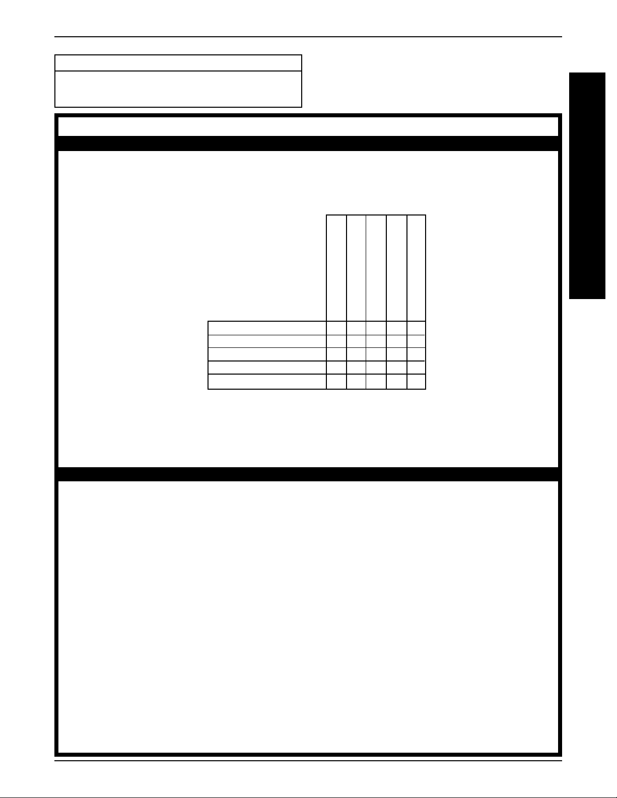
ST ABILITY
STABILITY WARNING
The position of the footrest, camber tube, back angle, the tautness of the back upholstery as well
as the user's condition are directly related to the wheelchairs stability. Any change to one (1) or
any combination of the five (5) may cause the wheelchair to decrease in stability. Use EXTREME
caution when using a new seating position.
Footrest Position
Camber Tube
Back Angle
Back Upholstery
User Condition
Footrest Position
Camber Tube
Back Angle
Back Upholstery
User Condition
●●
●
●●
✓✓
✓
✓✓
✓✓
✓
✓✓
✓✓
✓
✓✓
●●
✓✓
●
✓
●●
✓✓
●●
●
●●
✓✓
✓
✓✓
✓✓
✓✓
✓
✓
✓✓
✓✓
✓✓
✓
✓✓
✓✓
✓
✓✓
✓✓
✓✓
✓
✓
✓✓
✓✓
●●
✓✓
●
✓
●●
✓✓
✓✓
●●
✓
●
✓✓
●●
G
E
N
E
R
A
L
G
U
I
D
E
L
I
N
E
S
NOTE: When changes to the left hand column occur, follow across the chart and refer to the ✓ procedure to
maintain the proper stability, safety and handling of the racing chair.
OPERATING INFORMATION
WARNING
Unless otherwise noted, all service and adjustments should be performed while the wheelchair is
unoccupied.
T o determine and establish your particular safety limits, practice bending, reaching and transferring activities in several combinations in the presence of a qualified healthcare professional BEFORE attempting active use of the wheelchair.
DO NOT attempt to reach objects if you have to move forward in the seat.
DO NOT attempt to reach objects if you have to pick them up from the floor by reaching down
between your knees.
DO NOT lean over the top of the back upholstery to reach objects behind you as this may cause
the wheelchair to tip over.
DO NOT shift your weight or sitting position toward the direction you are reaching as the wheel-
chair may tip over.
DO NOT tilt the wheelchair without assistance.
DO NOT use an escalator to move a wheelchair between floors. Serious bodily injury may occur .
Before attempting to transfer in or out of the wheelchair, every precaution should be taken to
reduce the gap distance. Turn both casters parallel to the object you are transferring onto. Also
be certain the wheel locks are engaged to prevent the wheels from moving.
5

G
G
GENERAL GUIDELINESPROCEDURE 1
WARNING
DO NOT operate on roads, streets or highways.
o
E
N
E
R
A
L
U
I
D
E
L
I
N
E
S
DO NOT climb, go up or down ramps or traverse slopes greater than 9
DO NOT attempt to move up or down an incline with a water, ice or oil film.
DO NOT attempt to ride over curbs or obstacles. Doing so may cause your wheelchair to turn
over and cause bodily harm or damage to the wheelchair.
DO NOT use ANY parts, accessories, or adapters other than those authorized by Invacare.
DO NOT attempt to lift the wheelchair by any removable (detachable) parts. Lifting by means of
any removable (detachable) parts of a wheelchair may result in injury to the user or damage to
the wheelchair.
DO NOT stand on the frame of the wheelchair.
OPTIONAL TUBULAR FOOTREST ONLY - Check ALL Allen screws securing the tubular footrest to the
chair frame BEFORE using the wheelchair. ESPECIALLY if engaging in ANY rigorous activity.
Anti-tippers MUST BE attached at all times.
DO NOT use the footplate as a platform when getting in or out of the wheelchair.
ALW AYS wear your seat positioning strap. Inasmuch as the SEAT POSITIONING STRAP is an option on this
wheelchair (You may order with or without the seat positioning strap), Invacare strongly recommends
ordering the seat positioning strap as an additional safeguard for the wheelchair user.
.
S
A
F
E
T
Y
S
U
M
M
A
R
Y
TIRE PRESSURE
DO NOT use your wheelchair unless it has the proper tire pressure (p.s.i.). DO NOT overinflate the tires.
Failure to follow these suggestions may cause the tire to explode and cause bodily harm. The recommended tire pressure is on the sidewall of the tire.
Replacement of the tire or tube MUST be performed by a qualified technician.
WEIGHT TRAINING
Invacare DOES NOT recommend the use of its wheelchairs as a weight training apparatus. Invacare
wheelchairs have NOT been designed or tested as a seat for any kind of weight training. If occupant
uses said wheelchair as a weight training apparatus, Invacare shall NOT be liable for bodily injury and
the warranty is void.
WEIGHT LIMIT A TION
Invacare's Top End Terminator JR wheelchair has a weight limitation of 150 lbs.
SAFETY/HANDLING OF
WHEELCHAIRS
“Safety and Handling” of the wheelchair requires the close
attention of the wheelchair user as well as the assistant.
This manual points out the most common procedures
and techniques involved in the safe operation and maintenance of the wheelchair. It is important to practice and
master these safe techniques until you are comfortable
in maneuvering around the frequently encountered architectural barriers.
Use this information only as a “basic” guide. The techniques that are discussed on the following pages have
been used successfully by many.
Individual wheelchair users often develop skills to deal with
daily living activities that may differ from those described in
this manual. Invacare recognizes and encourages each
individual to try what works best for him/her in overcoming
architectural obstacles that they may encounter, however,
ALL WARNINGS and CAUTIONS given in this manual
MUST be followed. Techniques in this manual are a starting point for the new wheelchair user and assistant with
“safety” as the most important consideration for all.
6
GENERAL GUIDELINES PROCEDURE 1
Stability and Balance
WARNING
ALWAYS wear your seat positioning strap. Inasmuch as the SEAT POSITIONING STRAP is an option on this wheelchair (You may order with or
without the seat positioning strap), Invacare
strongly recommends ordering the seat positioning strap as an additional safeguard for the
wheelchair user.
Anti-tippers MUST BE attached at all times.
To assure stability and proper operation of your wheelchair, you must at all times maintain proper balance. Y our
wheelchair has been designed to remain upright and
stable during normal daily activities as long as you do
not move beyond the center of gravity.
Virtually all activities which involve movement in the wheelchair have an effect on the center of gravity. Invacare
recommends using seat positioning straps for additional
safety while involved in activities that shift your weight.
DO NOT lean forward out of the wheelchair any further
than stability will allow. Make sure casters are pointing in
the forward position whenever you lean forward. This
can be achieved by advancing the wheelchair and then
reversing it in a straight line.
Percentage of Weight Distribution
WARNING
DO NOT attempt to reach objects if you have to
move forward in the seat or pick them up from
the floor by reaching down between your knees.
The position of the footrest, camber tube, back
angle, the tautness of the back upholstery as well
as the user's condition are directly related to the
wheelchairs stability. Any change to one (1) or
any combination of the five (5) may cause the
wheelchair to decrease in stability. Use EXTREME
caution when using a new seating position.
Many activities require the wheelchair owner to reach, bend
and transfer in and out of the wheelchair. These movements will cause a change to the normal balance, the
center of gravity , and the weight distribution of the wheelchair. To determine and establish your particular safety
limits, practice bending, reaching and transferring activities in several combinations in the presence of a qualified
health-care professional BEFORE attempting active use
of wheelchair.
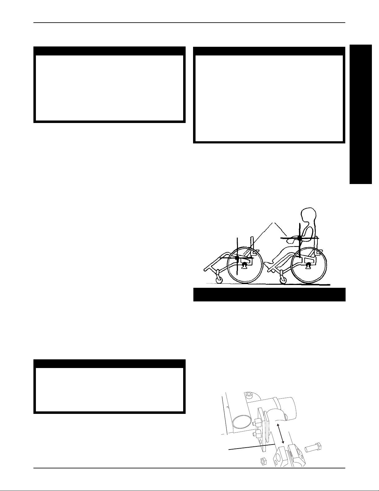
Center of Gravity
G
E
N
E
R
A
L
G
U
I
D
E
L
I
N
E
S
Coping with Everyday Obstacles
Coping with the irritation of everyday obstacles can be
alleviated somewhat by learning how to manage your
wheelchair. Keep in mind your center of gravity to maintain stability and balance.
A Note to Wheelchair Assistants
When assistance to the wheelchair user is required, remember to use good body mechanics. Keep your back
straight and bend your knees whenever tilting the wheelchair or traversing curbs, or other impediments.
WARNING
Do not attempt to lift a wheelchair by lifting on
any removable (detachable) parts. Lifting by
means of any removable (detachable) parts of
a wheelchair may result in injury to the user or
damage to the wheelchair.
Also, be aware of any removable (detachable) parts.
These must NEVER be used for hand-hold or lifting supports, as they may be inadvertently released, resulting in
possible injury to the user and/or assistant(s).
When learning a new assistance technique, have an
experienced assistant help you before attempting it alone.
Example: 46% 54% 103 lbs. 130 lbs.
UNOCCUPIED OCCUPIED
Proper positioning is essential for your safety . When reaching, leaning, bending forward, it is important to use the
front casters as a tool to maintain stability and balance.
LENGTHENING THE WHEELBASE will increase the stability and maintain standard maneuverability of wheelchair.
SHORTENING THE WHEELBASE will increase the
maneuverability, distribute additional weight onto the rear
wheels, and decrease the stability of the wheelchair.
LENGTHENING
SHORTENING
Telescoping
Tube
7
GENERAL GUIDELINESPROCEDURE 1
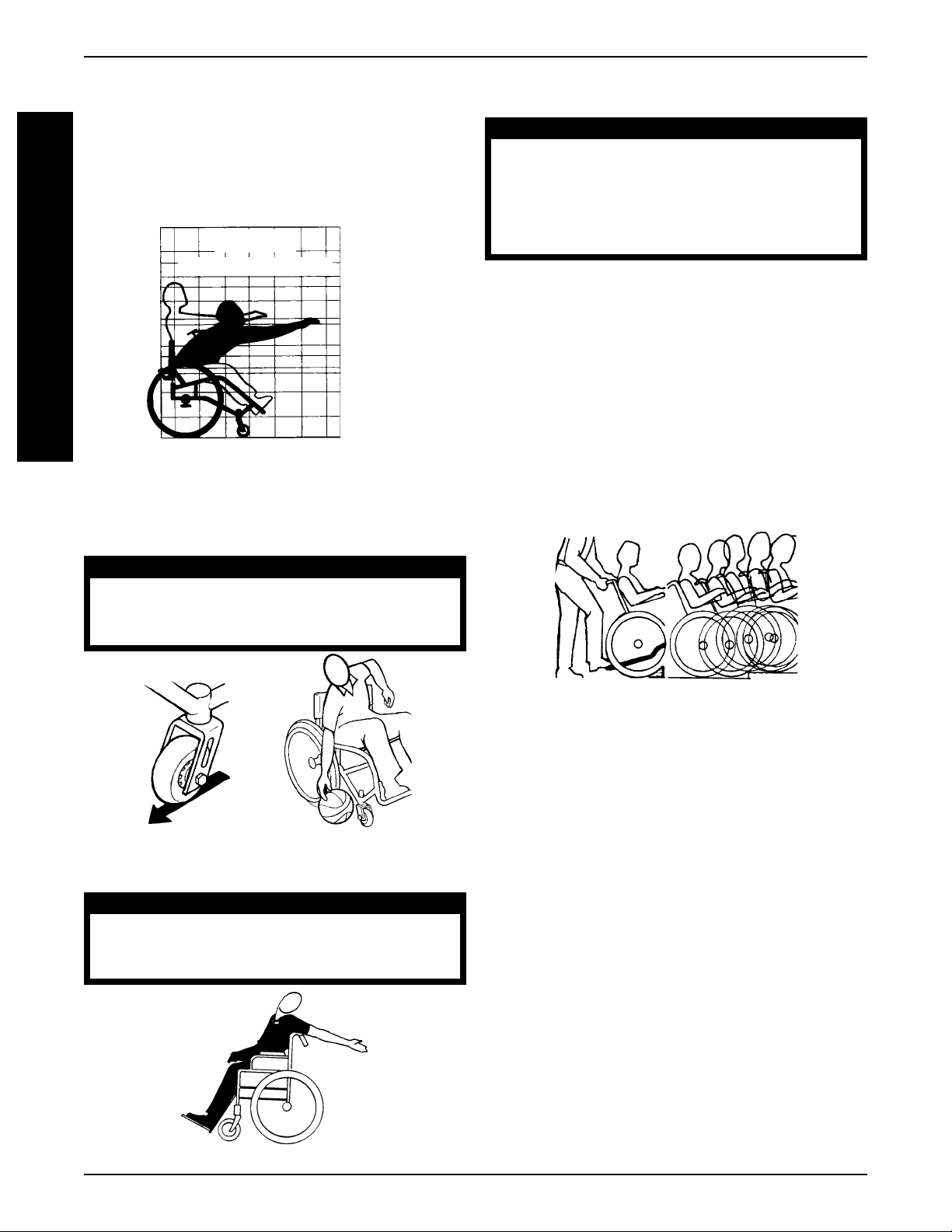
Functional Reach From a Wheelchair
The approximate reach-limit values shown in the accom-
G
panying graphs were derived on the basis of a sample of
E
91 male and 36 female wheelchair users. Note the differ-
N
ence between the maximum and the comfortable reach
E
limits, a subjective but important consideration in design.
R
G
D
A
L
FORWARD REACH
COMFORT MAXIMUM
U
I
E
L
I
N
E
S
0 8 16 24 37
INCHES
72
64
61
56
53
48
42
40
32
29
Reaching, Leaning and Bending Forward
Position the front casters so that they are extended as
far forward as possible and engage wheel locks.
INCHES
Tilting
WARNING
DO NOT tilt the wheelchair without assistance.
When lowering the front casters of the wheelchair ,
DO NOT let the wheelchair drop the last few inches
to the ground. This could result in injury to the occupant and/or damage to the wheelchair.
When tilting the wheelchair, an assistant should grasp the
back of the wheelchair on a non-removable (non-detachable) part. Inform the wheelchair occupant before tilting the
wheelchair and remind him/her to lean back. Be sure the
occupant’s feet and hands are clear of all wheels.
TILTING - CURBS:
After mastering the techniques of tilting the wheelchair,
use this procedure to tackle curbs, short stairs, etc.
METHOD 1 - Apply a continuous downward motion until
the balance point is achieved and the front casters clear
the curb. At this point, the assistant will feel a difference
in the weight distribution.
WARNING
DO NOT attempt to reach objects if you have to
move forward in the seat or pick them up from
the floor by reaching down between your knees.
REACHING, LEANING AND BENDING - FORWARD
Reaching, Leaning - Backwards
WARNING
DO NOT lean over the top of the back upholstery. This will change your center of gravity
and may cause you to tip over.
METHOD 1
Roll the wheelchair forward and slowly lower the front
casters onto the sidewalk. Do not let the wheelchair drop
the last few inches to the ground. This could result in
injury to the occupant. Push the wheelchair forward until
the rear wheels roll up and over the curb.
METHOD 2 - This method requires two (2) assistants.
The second assistant should be positioned at the front
of the wheelchair lifting upward on a non-removable (nondetachable) part of the wheelchair frame when lifting the
wheelchair and stabilizing the wheelchair when the wheelchair is being lowered to the ground.
The first assistant should stand on the sidewalk and turn
the wheelchair so that the rear wheels are against the
curb. The wheelchair should be tilted back to the balance point and, in one continuous upward movement,
the rear wheels should be pulled up and over the curb.
DO NOT return the front casters to the ground until the
wheelchair has been pulled backward far enough for
the front casters to clear the edge of the curb.
REACHING, LEANING - BACKW ARDS
8
GENERAL GUIDELINES
METHOD 2
PROCEDURE 1
G
E
N
E
R
A
L
Stairways
WARNING
ALWAYS wear your seat positioning strap. Inasmuch as the SEAT POSITIONING STRAP is an option on this wheelchair (You may order with or
without the seat positioning strap), Invacare
strongly recommends ordering the seat positioning strap as an additional safeguard for the
wheelchair user.
DO NOT attempt to lift the wheelchair by any
removable (detachable) parts. Lifting by means
of any removable (detachable) parts of a wheelchair may result in injury to the user or damage
to the wheelchair.
Extreme caution is advised when it is necessary
to move an occupied wheelchair up or down a
stairway. Invacare recommends using two (2) assistants and making thorough preparations. Make
sure to use ONLY secure, non-detachable parts
for hand-hold supports.
Follow this procedure for moving the wheelchair between
floors when an elevator is NOT available:
1. Turn the anti-tippers so they are facing UP.
2. After the wheelchair has been tilted back to the balance point, one assistant (in the rear) backs the
wheelchair up against the first step, while securely
grasping a non-removable (non-detachable) part of
the wheelchair for leverage.
3. The second assistant, with a firm hold on a nondetachable part of the framework, lifts the wheelchair up and over the stair and steadies it as the first
assistant places one foot on the next stair and repeats procedure.
ESCALA TORS? SORR Y!
DO NOT use an escalator to move a wheelchair
between floors. Serious bodily injury may occur .
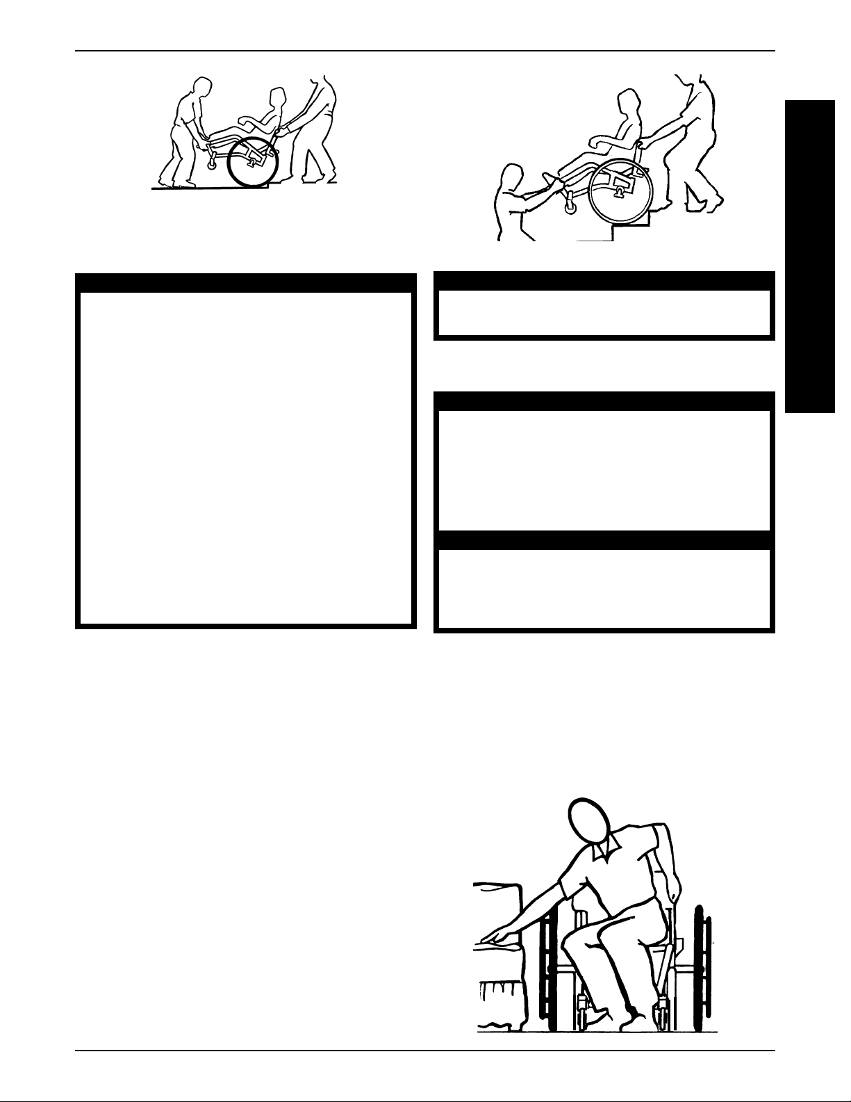
Transferring to and From Other Seats
WARNING
BEFORE attempting to transfer in or out of the
wheelchair , every precaution should be taken
to reduce the gap distance. Tu rn both casters
parallel to the object you are transferring onto.
Also be certain the wheel locks are engaged
to help prevent the wheels from moving.
CAUTION
When transferring, position yourself as far back as
possible in the seat. This will prevent damaged upholstery and the possibility of the wheelchair tipping forward.
NOTE: This activity may be performed independently provided you have adequate mobility and upper body strength.
Position the wheelchair as close as possible along side
the seat to which you are transferring, with the front casters pointing parallel to it. Engage wheel locks. Shift body
weight into seat with transfer.
During independent transfer, little or no seat platform will
be beneath you. Use a transfer board if at all possible.
G
U
I
D
E
L
I
N
E
S
4. The wheelchair should not be lowered until the last
stair has been negotiated and it has been rolled away
from the stairway.
5. Turn the anti-tippers so they are facing DOWN.
9

PROCEDURE 2
This Procedure includes the following:
SAFETY INSPECTION
S
Safety Inspection Checklist
A
F
SAFETY INSPECTION CHECKLIST
E
NOTE: Every six (6) months, take your wheelchair to a qualified technician for a thorough inspection and servicing.
T
Regular cleaning will reveal loose or worn parts and enhance the smooth operation of your wheelchair. To operate
Y
properly and safely , your wheelchair must be cared for just like any other vehicle. Routine maintenance will extend
I
the life and efficiency of your wheelchair. Clean upholstery with mild soap and water or spray disinfectant using a
sponge. DO NOT use bleach or wash in a washing machine.
N
S
Initial adjustments should be made to suit your personal body structure, preference and abilities. Thereafter follow
P
these maintenance procedures:
E
C
T
I
O
N
ITEM INITIALLY INSPECT/ INSPECT/ INSPECT/
ADJUST ADJUST ADJUST
WEEKLY MONTHLY PERIODICALLY
GENERAL
Wheelchair rolls straight (no excessive drag or pull to one side). X X
WHEEL LOCKS
Do not interfere with tires when rolling. X X
Pivot points free of wear and looseness. X X
Wheel locks easy to engage. X X
SEAT AND BACK UPHOLSTERY
Inspect for rips or sagging. X X
Inspect fastening flaps to ensure they securely latch. X X
REAR WHEELS
Adjustable Axle Position Camber Bar is securely tightened. X X X
Quick/Quad release axles lock properly. X X
No excessive side movement or binding when lifted and spun. X X
HANDRIMS
Inspect for signs of rough edges or peeling. X X
SPOKES
Inspect for bent or broken spokes. X X
All spokes uniformly tight. X X
FRONT CASTER
Inspect wheel/fork assembly for proper tension by spinning
caster; caster should come to a gradual stop. X X
Loosen/tighten locknut if wheel wobbles noticeably or
binds to a stop. X X
Wheel bearings are clean and free of moisture. X X X
CAUTION: As with any vehicle, the wheels and
tires should be checked periodically for cracks and
wear, and should be replaced.
TIRES
Inspect for flat spots and wear. X X
If pneumatic tires check for proper inflation. X X
CAUTION: As with any vehicle, the wheels and
tires should be checked periodically for cracks and
wear, and should be replaced.
FRONT SUSPENSION FORKS (If Equipped)
Inspect elastomers for proper lubrication. X
CLEANING
Clean upholstery and armrests. X X
10

TROUBLESHOOTING/MAINTENANCE
This Procedure includes the following:
PROCEDURE 3
Troubleshooting
Maintenance
TROUBLESHOOTING
CHAIR CHAIR SLUGGISH CASTER SQUEAKS LOOSENESS SOLUTIONS
VEERS VEERS TURN OR FLUTTERS AND IN CHAIR
RIGHT LEFT PERFORMANCE RATTLES
XXXX Check tires for correct
and equal pressure.
XXX XCheck for loose stem nuts.
XXCheck spokes and nipples.
XX X Check that both casters
contact the ground at the
same time.
MAINTENANCE
Maintenance Safety Precautions
WARNING
After ANY adjustments, repair or service and BEFORE
use, make sure all attaching hardware is tightened
securely - otherwise injury or damage may result.
CAUTION
DO NOT overtighten hardware attaching to the
frame. This could cause damage to the frame
tubing.
Suggested Maintenance Procedures
1. Before using your wheelchair, make sure all nuts and
bolts are tight. Check all parts for damage or wear
and replace. Check all parts for proper adjustment.
2. Keep quick/quad-release axles free of dirt and lint to
ensure positive locking and proper operation. Refer
ADJUSTING QUICK-RELEASE AXLES or AD-
to
JUSTING QUAD-RELEASE HANDLES in PROCEDURE 7 of this manual.
3. Oil quick-release axles at least once (1) a month (3-
DO NOT use your wheelchair unless it has the
proper tire pressure (p.s.i.). DO NOT overinflate the
tires. Failure to follow these suggestions may
cause the tire to explode and cause bodily harm.
in-1 oil
®
or equivalent).
WARNING
4. Recommended tire pressure is listed on the sidewall
of the tire.
CAUTION
As with any vehicle, the wheel s and tires should
be checked periodically for cracks and wear ,
and should be replaced.
5. Check the wheels and tires periodically for cracks
and wear. If damaged, have them replaced by a qualified technician.
6. Regularly check for loose spokes in the rear wheels. If
loose, have them adjusted by a qualified technician.
7. Periodically check handrims to ensure they are secured to the rear wheels. Refer to
PLACEMENT in PROCEDURE 7 of this manual.
8. Periodically adjust wheel locks in correlation to tire
wear. Refer to
PLACEMENT in PROCEDURE 7 of this manual.
9. Periodically check caster wheel bearings to make
sure they are clean and free from moisture. Use a
®
Teflon
10. FRONT SUSPENSION FORKS (if equipped) - Peri-
odically lubricate the the inside of the elastomers and
the shaft of the hex bolt that secures the elastomers to
the suspension tube with a silicone based lubricant.
11. Check upholstery for sagging, rips or tears.
lubricant if necessary.
WHEEL LOCK ADJUSTMENT/RE-
HANDRIM RE-
T
R
O
U
B
L
E
S
H
O
O
T
I
N
G
M
A
I
N
T
E
N
A
N
C
E
11
PROCEDURE 4 BACK
B
A
C
K
This Procedure includes the following:
Folding/Unfolding the Back
Changing the Back Angle
Adjusting the Back Height
Replacing Standard Back Upholstery
Replacing Custom Manual Adjustable Tension
Back Upholstery
Replacing the Spreader Bar
Replacing the Locking Mechanism in the Back Cane
Installing the Stroller Handles
WARNING
ALWAYS perform this procedure in the presence of
an assistant. The position of the footrest, camber
tube, back angle, the tautness of the back upholstery as well as the user's condition are directly re lated to the wheelchairs stability. Any change to
one (1) or any combination of the five (5) may cause
the wheelchair to decrease in stability. Use EXTREME
caution when using a new seating position.
After ANY adjustments, repair or service and BEFORE
use, make sure all attaching hardware is tightened
securely - otherwise injury or damage may result.
FOLDING/UNFOLDING THE BACK
(FIGURE 1)
WARNING
Back MUST be locked securely in place and all attaching hardware tight BEFORE using the wheelchair.
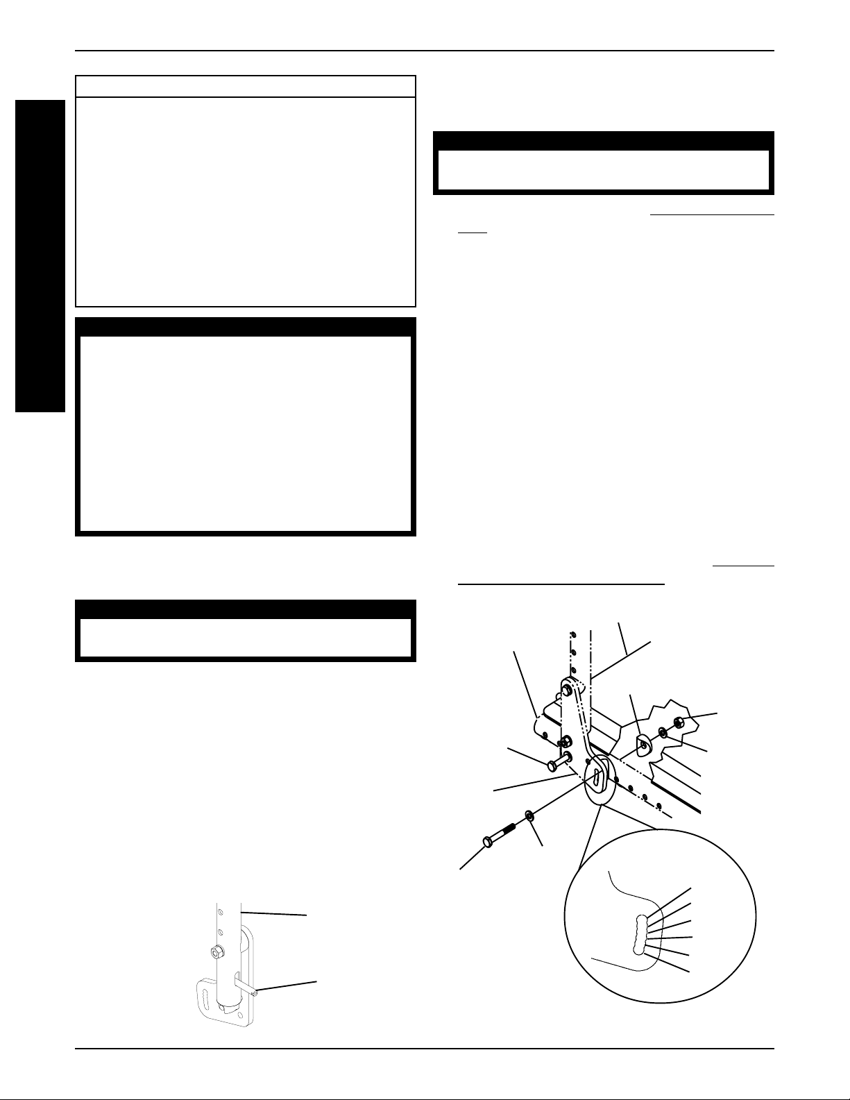
CHANGING THE BACK ANGLE
(FIGURE 2)
WARNING
The following procedure MUST be perform ed
by a qualified technician.
1. Remove the seat pan. Refer to
PAN in PROCEDURE 6 of this manual.
2. Loosen, but do not remove the rear hex screw
that secures the back angle plate to the wheelchair frame.
3. Remove the front hex screw, washers, coved
washer and locknut that secure the back angle
plate to the wheelchair frame.
4. Position the back angle plate to one (1) of six (6)
back angles shown in FIGURE 2.
5. Reinstall the front hex screw, washers and coved
washer and securely tighten with locknut. Refer to
FIGURE 2 for correct hardware orientation.
6. Securely tighten the rear hex screw that secures
the back adjustment plate to the wheelchair frame.
7. If wheelchair is equipped with cantilever arms,
adjust the angle of the cantilever arm so they remain parallel to the ground/floor. Refer to
ING CANTILEVER ARM ANGLE in PROCEDURE
5 of this manual.
Wheelchair
Frame
Seat Pan
REPLACING SEA T
ADJUST-
Folding the Back
1. Pull BOTH back release levers UP.
2. While holding BOTH back release levers, push the
back canes DOWN.
Unfolding the Back
1. Pull the back canes UP towards the rear of the
wheelchair there is an audible "click".
2. Push the back canes FORWARD to ensure they
are locked in place.
3. If the back canes are not locked in place, repeat
STEPS 1-2 until the back canes lock.
Back Cane
Back
Release
Lever
FIGURE 1 - FOLDING/UNFOLDING THE BACK
Rear Hex
Screw
(Loosen,
but do not
Remove)
Back
Angle
Plate
Front
Hex
Screw
12
Coved Washer
Locknut
Washer
Washer
FIGURE 2 - CHANGING THE BACK ANGLE
BACK
ANGLES
86°
90°
94°
98°
102°
106°
PROCEDURE 4BACK
ADJUSTING THE BACK HEIGHT
(FIGURE 3)
NOTE: If necessary, remove the back upholstery to
access mounting holes. Refer to REPLACING ST ANDARD BACK UPHOLSTERY or REPLACING CUSTOM MANUAL ADJUSTABLE TENSION BACK UPHOLSTERY in this procedure of the manual.
1. Remove the back height adjustment screws that
secure the back cane to the back upright.
2. Raise/lower the back canes to the desired height.
3. Align the mounting hole in each back cane with
the desired mounting hole in each back upright.
NOTE: Both back canes should be adjusted to the
same height.
4. Install the two (2) back height adjustment screws
through the back upright mounting holes determined
in STEP 3 and the back cane mounting holes.
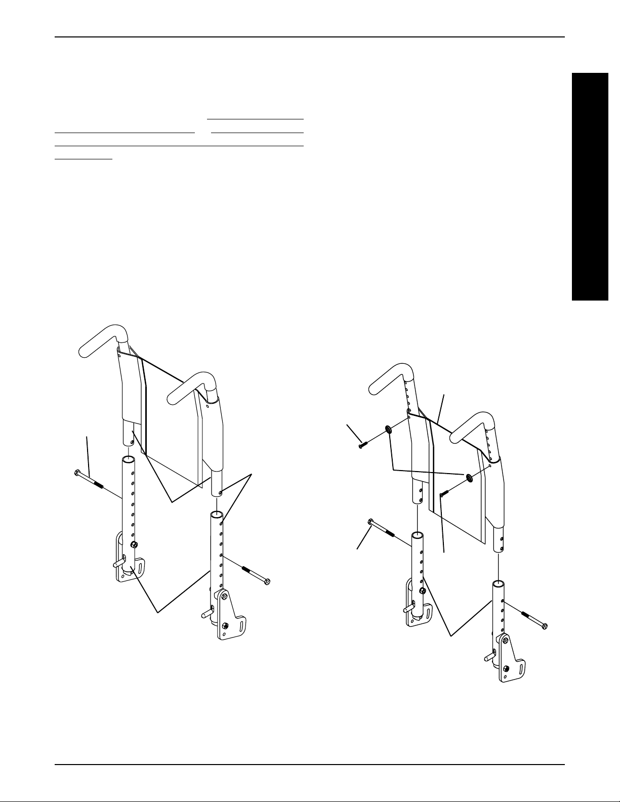
REPLACING STANDARD BACK
UPHOLSTERY (FIGURE 4)
1. Remove the back height adjustment screws that
secure the back cane to the back upright.
2. Slide the back assembly out of the back uprights.
3. Remove the two (2) screws and washers that secure the EXISTING back upholstery to the back
cane.
4. Slide the EXISTING back upholstery down and
off the back canes.
5. Slide the NEW back upholstery up and onto the
back canes.
6. Align the mounting hole in each back cane with
the desired mounting hole in each back upright.
NOTE: Both back canes should be adjusted to the
same height.
7. Install the two (2) back height adjustment screws
through the back upright mounting holes determined
in STEP 6 and the back cane mounting holes.
B
A
C
K
Back
Height
Adjustment
Screw
Mounting
Holes
Back
Canes
Back
Uprights
NOTE: Standard back upholstery shown for clarity.
FIGURE 3 - ADJUSTING THE BACK HEIGHT
Mounting
Screw
Washers
Back
Height
Adjustment
Screw
Back Upholstery
Mounting
Screw
Back
Uprights
13
FIGURE 4 - REPLACING ST ANDARD BACK
UPHOLSTERY
BACKPROCEDURE 4
B
A
C
K
REPLACING CUSTOM MANUAL
ADJUSTABLE TENSION BACK
UPHOLSTERY (FIGURE 5)
The Adjustable Tension Straps
The straps can be adjusted at various levels of tension to
accommodate individual end-users. The bottom two (2)
straps can be adjusted tightly to support and/or assist the
extensor muscles.
The Back Upholstery Cover
The back upholstery cover is designed for three (3)
reasons:
1. The first is as a modesty cover.
2. The second is to keep the cushion from sliding out of
the back of the wheelchair.
3. The third is a sacral support depending upon how far
or tight the flap is pulled under the seat cushion.
Replacing Adjustable Tension Back
Upholstery
1. Remove the back height adjustment screws that secure the back canes to the back uprights.
WARNING
After the adjustable tension back upholstery has
been positioned to the end-users individual
needs, the fastening straps MUST be securely
fastened BEFORE applying the back upholstery
cover . The adjustable back should be checked
whenever entering the wheelchair to ensure
that the fastening straps are securely fastened.
9. Secure the back upholstery cover (fastening strap)
to the back of the adjustable back upholstery (fastening strap).
10. Flip the back upholstery cover over the adjustable
back upholstery and secure the fastening straps
to the front of the adjustable back upholstery.
1 1. Lay the front portion of the back upholstery cover
on the seat pan.
12. Adjust the slack in the back upholstery cover and
then secure to the seat pan fastening straps.
Back Cane
2. Slide the back canes out of the back uprights.
3. Remove the two (2) screws and washers that secure
the EXISTING back upholstery to the back canes.
4. Slide the EXISTING back upholstery down and off
the back canes.
5. Stand behind the wheelchair and perform the following:
A. Slide anchor loop section of adjustable tension back
upholstery up onto the LEFT back cane with the upper grommet hole facing the rear of the wheelchair.
B. Slide adjuster strap section of adjustable tension back
upholstery up onto the RIGHT back cane with the
upper grommet hole facing the rear of the wheelchair.
6. Align the mounting hole in each back cane with the
desired mounting hole in each back upright.
NOTE: Both back canes should be adjusted to the same
height.
7. Install the two (2) back height adjustment screws
through the back upright mounting holes determined
in STEP 6 and the back cane mounting holes.
8. Slip adjuster straps through corresponding anchor
loops and adjust the back upholstery. Secure with
the fastening straps.
Back
Upright
Fastening Strap
Back Upholstery
Anchor Loop Section
Mounting Screw
Back Upholstery Adjuster Strap Section
Back Height
Adjustment
Screw
Back Upholstery Cover
Fastening Straps
Adjuster Strap
Anchor
Loop
Back
Cane
Upper
Grommet
Hole
14
FIGURE 5 - REPLACING CUSTOM MANUAL
ADJUST ABLE TENSION BACK UPHOLSTER Y

PROCEDURE 4BACK
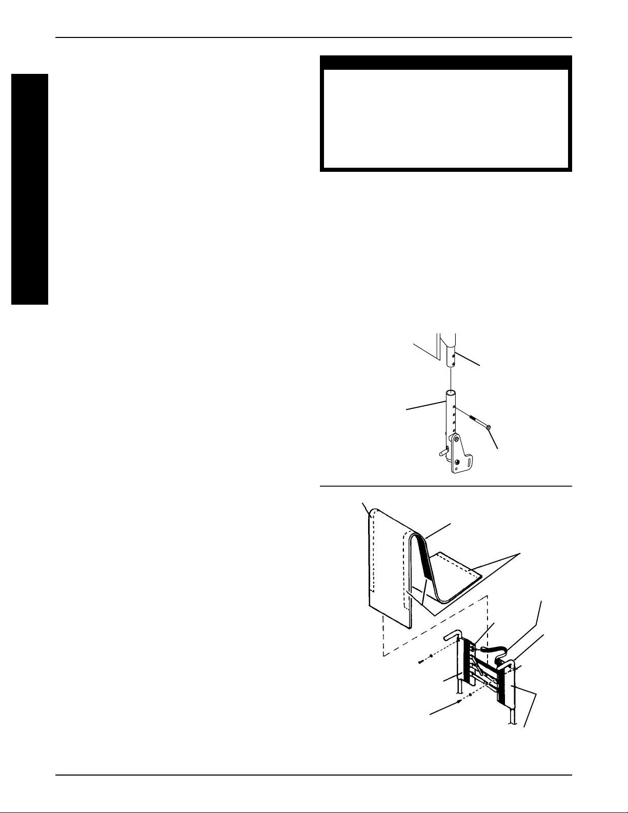
REPLACING THE SPREADER BAR
(FIGURE 6)
NOTE: Make sure the spreader bar is ALWAYS attached to the wheelchair.
1. Remove the back height adjustment screws that
secure the back canes to the back uprights.
2. Remove the cantilever arms, if necessary. Refer
INSTALLING/REMOVING CANTILEVER
to
ARMS in PROCEDURE 5 of this manual.
3. Loosen, but do not remove the two (2) set screws
that secure the EXISTING spreader bar to the back
canes.
4. Slide the EXISTING spreader bar off of the two
(2) back canes.
5. Slide the NEW spreader bar onto the back canes.
6. Securely tighten the two (2) set screws that secure the NEW spreader bar to the back canes.
7. Reinstall the cantilever arms, if necessary. Refer
INSTALLING/REMOVING CANTILEVER
to
ARMS in PROCEDURE 5 of this manual.
8. Align the mounting hole in each back cane with
the desired mounting hole in each back upright.
9. Install the two (2) back height adjustment screws
through the back upright mounting holes determined in STEP 8 and the back cane mounting
holes.
Mounting
Set
Screw
Hole
Back Cane
REPLACING THE LOCKING
MECHANISM IN THE BACK CANE
(FIGURE 7)
WARNING
The locking mechanism is spring loaded. Place
your free hand over the end of the back cane
to prevent the locking mechansim from springing out of the back cane.
1. Fold the back down. Refer to
ING BACK in this procedure of the manual.
2. Unscrew the actuator from the locking mechanism.
3. Remove the locking mechanism and spring from
the back cane.
NOTE: Inspect the spring and replace if necessary.
4. Slide the NEW spring and locking mechanism into
the back cane.
5. Make sure the angled end of the locking mechanism is at the bottom of the back cane.
NOTE: The long side of the locking mechanism should
be toward the actuator opening.
6. Push and hold the locking mechanism into the back
cane.
7. Screw the actuator through the actuator opening
and into the locking mechanism mounting hole.
8. Unfold the back. Refer to
BACK in this procedure of the manual.
FOLDING/UNFOLD-
FOLDING/UNFOLDING
B
A
C
K
Back
Height
Adjustment
Screw
Back
Uprights
FIGURE 6 - REPLACING THE SPREADER BAR
Spreader
Bar
Back Cane
Actuator Opening
Actuator
Spring
Locking
Mechanism
Angled End of the Locking Mechanism
FIGURE 7 - REPLACING THE LOCKING MECHANISM
IN THE BACK CANE
15
Mounting
Hole
Long Side of
Locking Mechanism

INSTALLING THE STROLLER
HANDLES (FIGURE 8)
BACKPROCEDURE 4
B
A
C
K
NOTE: If necessary , remove the foam grip on the push
handle BEFORE performing this procedure.
1. Slide the stroller handle onto the push handle.
2. Make sure to line up the mounting holes of the
stroller handle and the push handle.
3. Press and hold the button on the quick-release
pin.
4. While holding the button, insert the quick-release
pin through the stroller handle and push handle.
5. Pull on the stroller handle to make sure it is locked
securely in place.
6. Repeat STEPS 1-5 for the opposite stroller handle.
Stroller
Handle
Button
Quick-Release Pin
Push
Handle
FIGURE 8 - INST ALLING THE STROLLER HANDLES
16

PROCEDURE 5ARMS
This Procedure includes the following:
Using Cantilever Arms
Installing/Removing Cantilever Arms
Adjusting Cantilever Arm Height
Adjusting Cantilever Arm Angle
Replacing/Repositioning the Cantilever Arm
Locking Mechanism
Arm Pad Adjustment/Replacement
Installing T-Arm Sockets
Installing/Removing T-Arms
Adjusting the T-Arms
Replacing the T-Arm Locking Lever
WARNING
Never try to lift or tip the wheelchair by the
cantilever arms or T-arms, serious injury can
occur.
After ANY adjustments, repair or service and
BEFORE use, make sure all attachment hardware is tightened securely - otherwise, injury
or damage may occur.
USING CANTILEVER ARMS
(FIGURE 1)
1. Pull the locking mechanism actuator towards the
front of the wheelchair.
2. While holding the actuator, pull UP on the cantilever arm.
NOTE: If cantilever arms rub against rear wheels when
UP, increase the wheelbase width. Refer to ADJUSTING WHEELBASE WIDTH in PROCEDURE 7 of this
manual.
NOTE: If necessary , the locking mechanism in the cantilever arm can be repositioned so the cantilever arm
will flip DOWN instead of UP. Refer to
REPOSITIONING THE CANTILEVER ARM LOCKING MECHANISM in this procedure of the manual.
3. T o lock the cantilever arm, push DOWN until there
is an audible click.
4. Pull UP on the cantilever arm to make sure it is
locked in place.
REPLACING/
Adjustment Plate
REAR
Actuator
Top Hex Screw
and Coved Washer
Bottom Hex Screw
FIGURE 1 - USING CANTILEVER ARMS - INST ALLING/
REMOVING CANTILEVER ARMS - ADJUSTING
CANTILEVER ARM HEIGHT
Coved
Washers
Spacer
Back Cane
Locknuts
Washers
FRONT
Cantilever Arm
INSTALLING/REMOVING
CANTILEVER ARMS (FIGURE 1)
Installing
1. Insert the top hex screw of the partially assembled
cantilever arm assembly through the desired back
cane mounting hole.
NOTE: The partially assembled cantilever arm assembly includes the top hex screw, coved washers and
spacer, adjustment plate and cantilever arm.
NOTE: Make sure the adjustment plate is towards the
inside of the wheelchair.
2. Insert the bottom hex screw through the bottom
hole of the adjustment plate, the coved washer
and the back cane.
3. Secure the cantilever arm to the wheelchair with
the washers and locknuts as shown in FIGURE 1.
4. If desired, adjust the angle of the cantilever arm.
Refer to
in this procedure of the manual.
Removing
NOTE: When removing the locknuts and washers from
the cantilever arm assembly, leave the hex screws,
coved washers and spacer in place.
1. Remove the locknuts and washers from the top
and bottom hex screws.
ADJUSTING CANTILEVER ARM ANGLE
A
R
M
S
2. Remove the cantilever arm assembly from the
wheelchair frame.
17

PROCEDURE 5 ARMS
A
R
M
S
ADJUSTING CANTILEVER ARM
HEIGHT (FIGURE 1)
1. Remove the washers and locknuts from the top
hex screw and the bottom hex screw.
2. Pull the cantilever arm assembly with hex screws,
spacers, and coved washers away from the back
canes.
3. Reposition the cantilever arm assembly and hardware up or down as desired.
4. Insert the two (2) hex screws with hardware and
cantilever arm assembly into the desired back cane
mounting holes.
5. Secure the cantilever arm to the back canes with
the locknuts and washers as shown in FIGURE 1.
ADJUSTING CANTILEVER ARM
ANGLE (FIGURES 2 AND 3)
NOTE: This adjustment is recommended if the back
angle has been changed.
1. Flip the cantilever arm up and out of the way.
2. Remove the locknut that secures the locking pin
to the arm adjustment plate.
3. Refer to FIGURE 3 to determine the mounting hole
in the arm adjustment plate that will be used to
correspond to the back angle.
O
86
Back Angle Bracket
Arm
Adjustment
Plate
O
94
Back Angle Bracket
Arm
Adjustment
Plate
O
102
Back Angle Bracket
Arm
Adjustment
Plate
O
90
Back Angle Bracket
Arm
Adjustment
Plate
O
98
Back Angle Bracket
Arm
Adjustment
Plate
O
106
Back Angle Bracket
Arm
Adjustment
Plate
4. Securely tighten the locking pin and washer to the
adjustment plate with a locknut.
5. Repeat STEPS 1-4 for the opposite side, if necessary .
Adjustment Plate
Locking Pin
Locknut
Washer
FIGURE 2 - ADJUSTING CANTILEVER ARM ANGLE
FIGURE 3 - CORRESPONDING ARM ADJUSTMENT
TO BACK ANGLE
18

PROCEDURE 5ARMS
REPLACING/REPOSITIONING THE
CANTILEVER ARM LOCKING
MECHANISM (FIGURE 4)
CAUTION
The locking mechanism is spring loaded. Place
your free hand over the end of the cantilever
arm to prevent the locking mechanism from
springing out of the arm.
1. Flip the cantilever arm up and out of the way.
2. Unscrew the actuator from the locking mechanism.
3. Remove the locking mechanism and spring from
the cantilever arm.
NOTE: Inspect the spring and replace if necessary.
4. Slide the NEW spring and locking mechanism into
the cantilever arm.
5. Position the angled portion of the locking mechanism in one (1) of two (2) ways:
A. ANGLED PORTION FACING UP - Arm will
flip UP.
B. ANGLED PORTION FACING DOWN - Arm
will flip DOWN.
6. Push and hold the locking mechanism into the
cantilever arm.
7. Screw the actuator into the locking mechanism
mounting hole.
8. Flip the cantilever arm up/down to lock in place.
9. Pull down/up on the cantilever arm to ensure it
has locked in place.
ARMREST PAD ADJUSTMENT/
REPLACEMENT (FIGURE 5)
Armrest Pad Adjustment
1. Remove the phillips screw from the rear of the
armrest pad.
2. Reposition the cantilever slide tube to one (1) of
five (5) positions.
3. Align the mounting hole in the cantilever slide tube
with the desired mounting hole from STEP 2.
4. Install the phillips screw UP through the desired
mounting hole in the armrest tube and the cantilever slide tube mounting hole to secure the armrest pad to the armrest tube.
5. Repeat STEPS 1-4 for opposite armrest pad if
necessary.
Armrest Pad Replacement
1. Remove the phillips screw from the rear of the
armrest pad.
2. Remove the phillips screw from the front of the
armrest pad.
3. Remove the EXISTING armrest pad from the armrest tube.
4. Position the NEW armrest pad onto the armrest
tube and cantilever slide tube.
5. Secure the NEW armrest pad to the armrest tube
and cantilever slide tube with the two (2) phillips
screws.
A
R
M
S
Angled Portion of
Locking Mechanism
Spring
Cantilever Arm
Locking
Mechanism
Actuator
FIGURE 4 - REPOSITIONING/REPLACING THE
LOCKING MECHANISM IN THE
CANTILEVER ARM
Armrest
Tube
REAR Phillips Screw
Cantilever Slide Tube
FRONT Phillips Screw
FIGURE 5 - ARMREST P AD ADJUSTMENT/
REPLACEMENT
19

PROCEDURE 5 ARMS
A
R
M
S
INSTALLING T-ARM SOCKETS
(FIGURE 6)
1. Remove rear wheels from wheelchair. Refer to REMOVING/INSTALLING REAR WHEELS in PROCEDURE 7 of this manual.
2. Position the T-arm clamp on the wheelchair frame as
shown in FIGURE 6.
NOTE: T-arm socket must be positioned on outside of
wheelchair frame.
3. Install hex bolts through T-arm clamp, wheelchair frame
and coved washers and tighten securely with locknuts.
4. Position the T-arm socket inserts in the T-arm socket
as shown in FIGURE 6.
5. Line up the mounting holes in the T-arm socket with
the threaded holes in the T-arm clamp.
6. While holding the T-arm socket and the T-arm clamp
together, install the four (4) hex screws and washers
into mounting holes and tighten loosely .
7. Adjust the T-arm socket. Refer to
T-ARMS in this procedure of the manual.
8. Repeat STEPS 2-7 for opposite side of wheelchair .
9. Install the T-arm into the T-arm sockets in this procedure of the manual.
ADJUSTING THE
2. Slide T-arm into T-arm socket until the locking lever is in
the slot in the T-arm socket and an audible "click" is heard.
3. Pull up on T-arm to make sure T-arm is locked in place.
NOTE: If the T-arm does not slide in the T-arm socket
as desired, adjust the T-arm socket. Refer to ADJUSTING THE T-ARMS in this procedure of the manual.
4. Adjust the T-arm for desired height, width and depth,
if necessary . Refer to ADJUSTING THE T-ARMS in
this procedure of the manual.
5. Repeat STEPS 1-4 for opposite side of wheelchair .
Removing T-Arms
1. Press in on the locking lever and lift the T-arm straight
up and out of the T-arm socket.
NOTE: If the T-arm does not slide up and down in the Tarm socket as desired, adjust the T-arm socket. Refer to
ADJUSTING THE T-ARMS in this procedure of the manual.
2. Repeat STEP 2 for opposite side of the wheelchair .
Wheelchair Frame
T-Arm Clamp
T-Arm Socket
Inserts
Hex Bolts
Hex Screw
T-Arm
Socket
FIGURE 6 - INST ALLING T-ARM SOCKETS
Washer
Locknut
Coved
Washer
INSTALLING/REMOVING T-ARMS
(FIGURE 7)
Installing T-Arms
1. Position the T-arm over the T-arm socket on the
wheelchair frame.
NOTE: Make sure the locking lever is towards the front
of the wheelchair.
T-Arm
Wheelchair
Frame
T-Arm
Socket
FIGURE 7 - INST ALLING/REMOVING T- ARMS
Locking Lever
(Towards the
front of the
wheelchair.)
Slot
ADJUSTING THE T-ARMS
Adjusting T-Arm Height (FIGURE 8)
1. Unlock the T-arm by flipping the T-arm release lever
towards the inside of the wheelchair.
NOTE: If necessary , pull out on the T-arm release lever and rotate 180o so it can be flipped towards the
outside of the wheelchair.
20

PROCEDURE 5ARMS
2. Slide the T-arm to one (1) of:
A. Low Height T-Arms - Nine (9) positions.
B. High Height T-Arms - Seven (7) positions.
NOTE: If the inside T-arm post does not slide up and
down in the outside T-arm post as desired, perform
one (1) of the following:
A. Tighten - Tightening the set screws on the out-
side T-arm post will make it harder to move the
inside T-arm post up and down.
B. Loosen - Loosening the set screws on the out-
side T-arm post will make it easier to move the
inside T-arm post up and down.
3. Lock the T-arm by flipping the T-arm release lever towards the front of the wheelchair.
Inside T-Arm
Post
Set
Screws
Adjusting T-Arm Depth (FIGURE 10)
1. Remove the two (2) phillips screws that secure the
arm pad to the arm tube.
2. Remove the two (2) socket screws that secure the
arm tube to the T-arm post.
3. Reposition the arm tube on the T-arm post:
A. Desk Length Arms - to one (1) of three (3) posi-
tions depending on the desired arm pad depth.
B. Full Length Arms - to one (1) of five (5) posi-
tions depending on the desired arm pad depth.
NOTE: Additional positions are obtainable by turning
the arm tube 180o.
4. Re-secure the arm tube to the T-arm post with the
two (2) socket screws. Torque to 60-70 in./lbs.
5. Reattach the arm pad to the arm tube with the two (2)
phillips screws. Tighten securely .
6. Repeat for the opposite side, if necessary .
Arm Pad
A
R
M
S
Outside
T- Arm Post
T-Arm Release Lever -
Unlocked Position
T-Arm Release Lever - Locked Position
FIGURE 8 - ADJUSTING T-ARM HEIGHT
Adjusting T-Arm Width (FIGURE 9)
1. Remove the two (2) phillips screws that secure the
arm pad to the arm tube.
2. Turn the arm pad around and reposition the arm pad
on the arm tube.
3. Re-secure the arm pad to the arm tube with the two
(2) phillips screws. Tighten securely.
4. Repeat for the opposite side, if necessary .
Arm Pad
Arm Tube
Phillips
Screw
FIGURE 9 - ADJUSTING T-ARM WIDTH
Phillips Screw
Arm Tube
Socket
Screws
Phillips
Screw
T-Arm Post
FIGURE 10 - ADJUSTING T-ARM DEPTH
NOTE: If
necessary, turn
arm tube 180
to obtain two
(2) positions.
Phillips Screw
o
Adjusting T-Arm Sockets (FIGURE 11)
NOTE: Perform this procedure if the T-arm is too loose
in the socket or does not easily slide up and down in
the socket.
1. Remove the rear wheels from the wheelchair, if necessary. Refer to REMOVING/INSTALLING REAR
WHEELS in PROCEDURE 7 of this manual.
2. Loosen, but do not remove the four (4) hex screws
and washers that secure T-arm socket to T- arm clamp.
NOTE: The T-arm socket will disassemble if the four
(4) hex screws and washers are removed.
21

PROCEDURE 5 ARMS
A
R
M
S
3. Slide the T-arm into the T-arm socket until the locking
lever is in the slot in the T-arm socket and an audible
"click" is heard.
4. Squeeze the T-arm socket the T-arm clamp together
until the socket is flush with the T-arm.
5. While holding the T-arm socket and the T-arm clamp
together, tighten the four (4) hex screws and washers.
Tighten securely.
6. Press in on the locking lever and lift the T-arm straight
up and out of the T-arm socket.
7. Repeat STEPS 3-6, if necessary until the T-arm slides
in the T-arm socket as desired.
8. If necessary, install rear wheels. Refer to
ING/INSTALLING REAR WHEELS in PROCEDURE
7 of this manual.
T-Arm
REMOV-
WARNING
The locking lever is spring loaded. Place your free
hand over the locking lever to prevent the parts
from springing off of the bottom bracket, otherwise parts may be lost or injury may occur.
3. Remove EXISTING locking lever and spring from
bottom bracket.
NOTE: Inspect the spring and replace if necessary .
4. Position spring on bottom bracket as shown in FIGURE 12.
5. Position NEW locking lever onto spring and bottom
bracket (DETAIL "A").
NOTE: Make sure the two (2) extended ends of the spring
are inside the notch in the locking lever.
6. Line up the mounting holes in the NEW locking lever,
spring and bottom bracket.
WARNING
DO NOT over tighten locknut that secures locking lever to bottom bracket. Over tightening this locknut will
prevent locking lever from operating properly, possibly
causing injury.
T-Arm Clamp
Hex Screws
and Washers
Slot
Locking Lever
FIGURE 11 - ADJUSTING T-ARM SOCKETS
Hex Screws
and Washers
T-Arm Socket
REPLACING THE T-ARM LOCKING
LEVER (FIGURE 12)
1. Remove T-arm from wheelchair. Refer to INSTALLING/REMOVING T-ARMS in this proce-
dure of the manual.
2. Remove the phillips bolt and locknut that secure
the EXISTING locking lever to the bottom bracket.
7. Install phillips bolt and tighten securely with locknut.
8. Install the T-arm onto the wheelchair. Refer to
STALLING/REMOVING T-ARMS in this procedure
of the manual.
DET AIL "A" - MOUNTING THE SPRING
Mounted
Extended Ends
Spring
Bottom
Bracket
Phillips Bolt
FIGURE 12 - REPLACING THE T-ARM LOCKING LEVER
Spring
Notch
IN-
Locknut
Locking
Lever
22

SEAT PROCEDURE 6
This Procedure includes the following:
Replacing Seat Pan
Adjusting Rear Seat Height
Adjusting Seat Depth
Adjusting Seat Width
Adjusting Front Seat-to-Floor Height
WARNING
After ANY adjustments, repair or service and BEFORE
use, make sure all attaching hardware is tightened
securely - otherwise injury or damage may result.
REPLACING SEAT PAN (FIGURE 1)
1. Remove the seat cushion from the seat pan.
2. Remove the four (4) phillips screws, locknuts and
spacers (if present) that secure the seat pan to the
frame clamps.
3. Position NEW seat pan on wheelchair frame, aligning seat pan mounting holes with frame clamps.
4. Secure the seat pan to the frame clamps with the
four (4) phillips screws, locknuts and spacers (if
present).
Phillips Screws
Seat Pan
Mounting
Holes
FRONT OF
WHEELCHAIR
Seat Pan
REAR OF
WHEELCHAIR
Spacer
Frame
Clamps
SP ACER HEIGHT DIFFERENCE
NONE 2-inch
1-inch 1-inch
2-inch NONE
1. Perform STEPS 1-2 of
2. Insert or remove spacers on top of the REAR frame clamps.
3. Perform STEPS 3-4 of
REPLACING THE SEA T PAN.
REPLACING THE SEA T PAN.
ADJUSTING SEAT DEPTH
(FIGURES 2 AND 3)
WARNING
This procedure must be perf ormed by a qualified technician ONLY .
The position of the footrest, camber tube, back
angle, the tautness of the back upholstery as well
as the user's condition are directly related to the
wheelchairs stability. Any change to one (1) or any
combination of the five (5) may cause the wheelchair to decrease in stability. Use EXTREME caution
when using a new seating position.
NOTE: Note the position of the front hex screw before
removing to ensure proper reinstallation.
1. Remove the hex screws, washers, coved spacers
and locknuts that secure the back angle brackets to
the wheelchair frame.
2. Refer to the chart in FIGURE 3 to determine mounting positions for corresponding seat depths.
3. Position the back assembly with the mounting position determined in STEP 2.
4. Secure the back assembly to the wheelchair frame with
the hex screws, washers, coved washers and locknuts.
Refer to FIGURE 2 for correct hardware orientation.
S
E
A
T
Locknuts
Wheelchair Frame
FIGURE1 - REPLACING SEA T P AN
ADJUSTING REAR SEAT HEIGHT
(FIGURE 1)
NOTE: The wheelchair frame is designed to create a
2-inch height difference between the front and the rear
of the seat pan. If desired, spacers can be added at
the rear of the seat pan to decrease this height difference. Refer to the chart below for the proper spacers.
Back
Assembly
Back
Angle
Bracket
Rear
Hex
Screw
Front Hex Screw
FIGURE 2 - ADJUSTING SEA T DEPTH
23
Small Coved
Spacers
Washers
Large
Coved
Spacers
Washers
Locknuts
Wheelchair
Frame

PROPER MOUNTING HOLES FOR BACK ANGLE BRACKET
SEAT PROCEDURE 6
S
E
A
T
Use these mounting
holes ONL Y
987654321
NEVER use this mounting hole for the
back angle bracket
Rear--------Wheelchair-------Front
SHORT FRAME
Mounting
Holes 7 and 9
Mounting
Holes 6 and 8
NEVER use these mounting holes for
the back angle bracket
LONG FRAME
BACK POSITION FOR 16-INCH SEA T DEPTHBACK POSITION FOR 14-INCH SEA T DEPTH
Mounting
Holes 7 and 9
BACK POSITION FOR 15-INCH SEA T DEPTHBACK POSITION FOR 13-INCH SEA T DEPTH
Mounting
Holes 6 and 8
BACK POSITION FOR 14-INCH SEA T DEPTHBACK POSITION FOR 12-INCH SEA T DEPTH
Mounting
Holes 5 and 7
Mounting
Holes 4 and 6
Mounting
Holes 3 and 5
Mounting
Holes 2 and 4
Mounting
Holes 1 and 3
Mounting
Holes 5 and 7
BACK POSITION FOR 13-INCH SEA T DEPTHBACK POSITION FOR 11-INCH SEA T DEPTH
Mounting
Holes 4 and 6
BACK POSITION FOR 12-INCH SEA T DEPTHBACK POSITION FOR 10-INCH SEA T DEPTH
Mounting
Holes 3 and 5
BACK POSITION FOR 11-INCH SEA T DEPTHBACK POSITION FOR 9-INCH SEA T DEPTH
Mounting
Holes 2 and 4
BACK POSITION FOR 10-INCH SEA T DEPTHBACK POSITION FOR 8-INCH SEA T DEPTH
Mounting
Holes 1 and 3
FIGURE 3 - ADJUSTING SEA T DEPTH
24

SEAT PROCEDURE 6
ADJUSTING SEAT WIDTH (FIGURE 4)
WARNING
The following procedure should only be performed by a qualified technician.
1. Remove the EXISTING footplate from the wheelchair. Refer to PROCEDURE 8 of this manual.
2. Remove the EXISTING back upholstery from the
wheelchair. Refer to PROCEDURE 4 of this
manual.
3. Remove the EXISTING spreader bar from the
wheelchair. Refer to
SPREADER BAR in PROCEDURE 4 of this
manual.
4. Remove the EXISTING seat pan from the wheelchair. Refer to
cedure of the manual.
NOTE: Retain the attachment hardware for installation of the NEW seat pan.
5. Remove the axle tube from the wheelchair. Refer
to REPLACING AXLE TUBE in PROCEDURE 7
of this manual.
6. Remove the four (4) hex screws and eight (8)
coved washers that secure the two (2) EXISTING
crossmembers to the wheelchair frame.
7. Remove the four (4) frame clamps from the EXISTING two (2) crossmembers.
8. Install the four (4) frame clamps onto the NEW (2)
crossmembers.
9. Secure the two (2) NEW crossmembers to the front
and rear mounting holes in the wheelchair frame
with the hex screws and coved washers removed
in STEP 5.
10. Install the NEW axle tube. Refer to
AXLE TUBE in PROCEDURE 7 of this manual.
11. Install the NEW seat pan using the EXISTING
hardware. Refer to
procedure of the manual.
12. Install the NEW back upholstery onto the wheelchair. Refer to PROCEDURE 4 of this manual.
13. Install the NEW spreader bar onto the wheelchair .
Refer to
PROCEDURE 4 of this manual.
14. Install the NEW footplate onto the wheelchair . Refer to PROCEDURE 8 of this manual.
REPLACING SEA T P AN in this pro-
REPLACING SEA T PAN in this
REPLACING THE SPREADER BAR in
REPLACING THE
REPLACING
Hex Screws
Coved
Washers
Crossmember
Front Mounting Hole
FIGURE 4 - ADJUSTING SEA T WIDTH
Crossmember
Rear
Mounting
Hole
Wheelchair
Frame
ADJUSTING FRONT
SEAT-TO-FLOOR HEIGHT
WARNING
The position of the footrest, seat angle, back
angle, seating system/upholstery, caster size and
position, rear wheel size and position, anti-tippers,
as well as the user condition directly relate to the
stability of the wheelchair. Any change to one
(1) or any combination of the ten (10) may cause
the wheelchair to decrease in stability. EXTREME
care MUST be taken when changing the stability
of the wheelchair . Refer tothe chart in
PROCEDURE 1 o f this manual.
Determining Frame Height (FIGURE 5)
Terminator Jr. Frames come in Short and Tall.
1. To determine frame height, measure from the bottom of the caster headtube to the top of the seat rail.
2. Refer to the chart to determine the frame size.
HEIGHT (INCHES) FRAME SIZE
7-3/4 SHORT
10-1/2 T ALL
Seat Rail
HEIGHT
(INCHES)
FIGURE 5 - DETERMINING FRAME HEIGHT
ST ABILITY in
Bottom of
Caster
Headtube
S
E
A
T
25

SEAT PROCEDURE 6
S
E
A
T
Front Seat-to-floor Height Adjustment
NOTE: Refer to STABILITY in PROCEDURE 1 for
warnings concerning wheelchair stability .
Seat-to-floor height is determined by measuring from
the top of the seat rail to the ground/floor.
The different seat-to-floor heights are possible by using different combinations of rear wheel size and axle
tube position.
1. Refer to the chart below to determine available
front seat-to-floor heights for each wheelchair
frame height.
2. Determine the changes needed to the rear wheels
and axle tube by reading across the chart for the
seat-to-floor height determined in STEP 1.
3. Refer to REPOSITIONING THE AXLE TUBE in
PROCEDURE 7 of the manual to adjust the axle
tube position.
4. After adjusting the axle tube, the front casters may
need to be repositioned to ensure the caster
headtubes are perpendicular to the ground. Refer
to
ADJUSTING FRONT CASTER HEIGHT in
PROCEDURE 7.
5. Anti-tipper height (if applicable) must be adjusted
to maintain 1-1/2 to 2-inch clearance between the
bottom of the anti-tipper wheels and the floor. Refer
to
ANTI-TIPPER REPLACEMENT/ADJUST-
MENT in PROCEDURE 8 of this manual.
6. Ensure wheel locks engage properly. Refer to
WHEEL LOCK ADJUSTMENT/REPLACEMENT
in this procedure of the manual.
SHORT FRAME SEA T-TO-FLOOR HEIGHTS
FRONT SEAT-TO-FLOOR HEIGHT AXLE TUBE POSITION
REAR WHEEL SIZE (INCHES)
18 20 22 24
13-inch Upper N/A N/A N/A
14-inch Center Upper N/A N/A
15-inch Lower Center Upper N/A
16-inch N/A Lower Center Upper
17-inch N/A N/A Lower Center
18-inch N/A N/A N/A Lower
LONG FRAME SEAT-TO-FLOOR HEIGHTS
FRONT SEAT-TO-FLOOR HEIGHT REAR WHEEL SIZE (INCHES)
AXLE TUBE POSITION
20 22 24
16-inch Upper N/A N/A
17-inch Center Upper N/A
18-inch Lower Center Upper
19-inch N/A Lower Center
20-inch N/A N/A Lower
NOTE: Rear Seat-to-Floor height is two (2) inches shorter than Front Seat-to-Floor height.
NOTE: The Front Seat-to-Floor heights in the chart are determined using a 5-inch front caster.
NOTE: Refer to
Center and Lower axle tube positions.
REPOSITIONING THE AXLE TUBE in PROCEDURE 7 for an explanation of the Upper,
26

WHEELS PROCEDURE 7
This Procedure includes the following:
Removing/Installing Rear Wheels
Adjusting Quick-Release Axles
Installing Quad-Release Axles
Adjusting Quad-Release Handles
Handrim Replacement
Repairing/Replacing Rear Wheel, Tire/Tube
Opening/Closing Clamps
Adjusting Rear Wheel Camber
Determining/Adjusting Toe in/T oe out
Adjusting Wheelbase Length
Adjusting Wheelbase Width
Replacing Axle Tube
Repositioning the Axle Tube
Repositioning/Replacing Front Casters
Adjusting Front Caster Height
Wheel Lock Adjustment/Replacement
WARNING
After ANY adjustments, repair or service and BEFORE
use, make sure all attaching hardware is tightened
securely - otherwise injury or damage may result.
WARNING
During contact activities, Invacare recommends
inserting quick-release axles with the head end
to the inside of the wheelchair to prevent accidental release.
5. If there is too much movement of the rear wheel assembly in a back and forth motion, refer to
ING QUICK-RELEASE AXLES or ADJUSTING
QUAD-RELEASE HANDLES in this procedure of the
manual.
Quick-Release
Axle
Rear Wheel
Detent Pin
NOTE: Quad-Release Axle not shown. Locking pins the
same as Quick-Release Axle
FIGURE 1 - REMOVING/INST ALLING REAR WHEELS
Locking Pins
ADJUST-
Wheelchair
Frame
ADJUSTING QUICK-RELEASE
AXLES (FIGURE 2)
W
H
E
E
L
S
REMOVING/INSTALLING REAR
WHEELS (FIGURE 1)
CAUTION
Changing the size of the rear wheels can affect
the perfor mance of the wheelchair. Contact Invacare at the telephone numbers on the back
of this manual BEFORE changing rear wheel size.
1. Perform one (1) of the following:
QUICK-RELEASE - Push in the tip of the quick-release
axle and pull axle and wheel away from the wheelchair.
QUAD-RELEASE - Lift UP on the handle of the quadrelease axle and pull axle and wheel away from the
wheelchair.
2. Repeat STEP 1 for the opposite rear wheel.
3. Reinstall the rear wheel s onto the wheelchair by reversing STEPS 1-2.
WARNING
Pull on the rear wheel to make sure the detent pin
and locking pins of the quick/quad-release axle
are fully released BEFORE operating wheelchair.
Keep locking pins clean.
1. Remove rear wheel and quick-release axle from the
wheelchair. Refer to
REAR WHEELS in this procedure of the manual.
2. Depress detent pin in the quick-release axle and slide
axle through the wheel hub.
3. Release detent pin ensuring that the locking pins are
fully released.
4. Increase or decrease end play by adjusting the locknut on the end of the quick-release axle.
5. Reinstall rear wheel onto the wheelchair. Refer to
REMOVING/INSTALLING REAR WHEELS in this
procedure of the manual.
Adjustable Axle Position
Camber Bar
Locking
Pins
NOTE: End of Quick
Release axle is shown
for reference only. It is
not visible when
inserted into camber bar
FIGURE 2- ADJUSTING QUICK-RELEASE AXLES
REMOVING/INSTALLING
Locknut
Detent
Pin
Wheel
Hub
Quick
Release Axle
27

WHEELSPROCEDURE 7
W
H
E
E
L
S
INSTALLING QUAD-RELEASE
AXLES (FIGURE 3)
1. Remove rear wheel and the EXISTING quick-release
axle from the wheelchair. Refer to
STALLING REAR WHEELS in this procedure of the
manual.
2. Remove EXISTING quick-release axle from rear
wheel.
3. Insert NEW quad-release axle through rear wheel
hub.
4. Slide locking collar onto quad-release axle until it is snug
against rear wheel and tighten securely with allen screw.
5. Reinstall rear wheel and the quad-release axle onto
the wheelchair. Refer to
REAR WHEELS in this procedure of the manual.
6. Flip the handle of the quad-release axle down to release the detent pin ensuring that the locking pins
are fully released.
7. If detent pin does not fully release, proceed to
ING QUAD-RELEASE HANDLE IN AND/OR OUTin
this procedure of the manual.
8. Repeat STEPS 1-7 for the opposite rear wheel.
Quad
Release
Axle
REMOVING/INSTALLING
Allen
Screw
REMOVING/IN-
ADJUST-
Adjustable Axle
Position
Camber Bar
3. Make the following adjustments:
If the quad-release handle is not releasing the lock-
ing pins completely, rotate the quad-release handle
approximately one-quarter (1/4) turn CLOCKWISE.
If the quad-release handle hits the spokes of the rear
wheel when assembled, rotate the quad-release
handle approximately one-quarter (1/4) turn COUNTERCLOCKWISE.
4. Tighten the locking screw.
5. Reinstall the rear wheel and quad-release axle onto
the wheelchair. Refer to
REAR WHEELS in this procedure of the manual.
6. Flip the handle of the quad-release axle down to release the detent pin ensuring that the locking pins
are fully released.
7. Repeat the above procedures until the quad-release
axle locks correctly .
REMOVING/INSTALLING
Removing Play From Rear Wheels
NOTE: The adjusting locknut on the quick-release axles
originally performed this function.
1. With the rear wheel and quad-release axle still mounted
onto the wheelchair, make the following adjustment:
Tighten the length adjusting screw until there is no
in and out movement of the quad-release axle and
rear wheel.
NOTE: End of
Quad Release
axle shown for
reference only .
Rear Wheel
Hub
FIGURE 3 - INST ALLING QUAD-RELEASE AXLES
Locking
Collar
It is not visible
when inserted
into camber bar
ADJUSTING QUAD-RELEASE
HANDLES (FIGURE 4)
In and/or Out
1. Remove rear wheel and the quad-release axle from
the wheelchair. Refer to
REAR WHEELS in this procedure of the manual.
2. Loosen the locking screw.
REMOVING/INSTALLING
Quad Release
Handle
Locking
Screw
ADJUSTING QUAD-
RELEASE HANDLE IN/
AND OR OUT
REMOVING PLAY
FROM REAR
WHEELS
FIGURE 4 - ADJUSTING QUAD-RELEASE HANDLES
Adjusting
Locknut (On
Quick-Release
Axle)
Camber Bar
Locking Pins
Length
Adjustment
Screw
HANDRIM REPLACEMENT
(FIGURE 5)
1. Remove the rear wheel from the wheelchair. Refer to
REMOVING/INST ALLING REAR WHEELS in this
procedure of the manual.
28

WHEELS PROCEDURE 7
WARNING
Tire MUST be FULLY deflated BEFORE any disassembly procedures are per formed. Otherwise
injury or damage may result.
2. Remove all air from the tube by pressing down on the
pin in the center of the valve stem.
3. While carefully holding the tire, tube and rim strip to
one side, hold the allen screws and remove the locknuts that secure the handrim to the rear wheel.
4. Remove the EXISTING handrim.
5. Install NEW handrim by reversing STEPS 2-4.
WARNING
DO NOT inflate tire until it is completely assembled.
Otherwise injury or damage may result.
6. Inflate tire to correct psi rating on the sidewall of tire.
7. Reinstall rear wheel to the wheelchair. Refer to
MOVING/INSTALLING REAR WHEELS in this procedure of the manual.
8. Repeat STEPS 1-7 for opposite rear wheel if necessary.
Screw
Handrim
Locknut
FIGURE 5 - HANDRIM REPLACEMENT
RE-
Allen
REPAIRING/REPLACING REAR
WHEEL, TIRE/TUBE
WARNING
Replacement of the tire or tube MUST be performed by a qualified technician.
CAUTION
Changing the size of the rear wheels can affect
the performance of the wheelchair. Contact Invacare at the numbers on the back cover BEFORE performing this procedure.
NOTE: If replacing rear wheels with a different size than
what was originally on the wheelchair, the front caster height
must also be changed to keep the wheelchair frame parallel
to the floor. Refer to
HEIGHT in this procedure of the manual ONL Y after contacting Invacare. Anti-tipper height (if applicable) must also
be adjusted to maintain 1-1/2 to 2-inch clearance between
bottom of the anti-tipper wheels and the floor. Refer to
TIPPER REPLACEMENT/ADJUSTMENT in PROCEDURE 8 of this manual.
ADJUSTING FRONT CASTER
ANTI-
OPENING/CLOSING CLAMPS
(FIGURE 6)
WARNING
QUICK RELEASE LEVERS - Make sure the quick re lease levers are in the CLOSED position BEFORE
using the wheelchair , otherwise personal injury or
damage to the wheelchair may result.
ST ANDARD CAMBER OR RECEIVER TUBE CLAMPS
- Make sure the hex screws and locknuts are se curely tightened BEFORE using the wheelchair,
otherwise personal injury or damage to the
wheelchair may result.
CAUTION
DO NOT close the quick-release levers or tighten the
hex screws and locknuts without camber inserts in
the axle tube. Damage to the axle tube will occur .
Camber Clamps
1. Perform one (1) of the following to open a camber clamp:
A. QUICK RELEASE LEVERS - Pull the quick re-
lease lever to the open position.
B. STANDARD CAMBER CLAMPS - Loosen, but
do not remove the hex screw and locknut on the
camber clamp.
2. Perform one (1) of the following to close a camber clamp:
A. QUICK RELEASE LEVERS - Push the quick
release lever on the camber clamps to the closed
position.
B. STANDARD CAMBER CLAMPS - Securely tighten
the hex screw and locknut to secure the axle tube.
Receiver Tube Clamps
NOTE: The receiver tube clamps are used ONLY to
adjust wheelbase length.
1. Perform one (1) of the following to open a receiver
tube clamp:
A. QUICK RELEASE LEVERS - Pull the quick re-
lease levers on the receiver tube clamps to the
open position.
B. STANDARD RECEIVER TUBE CLAMPS -
Loosen, but do not remove the hex screws and
locknuts on the receiver tube clamps.
2. Perfrom one (1) of the following to close a receiver
tube clamp:
A. QUICK RELEASE LEVERS - Push the quick
release lever on the receiver tube clamps to the
closed position.
B. STANDARD RECEIVER TUBE CLAMPS -
Tighten the hex screw and locknut on the receiver
tube clamp.
W
H
E
E
L
S
29

WHEELSPROCEDURE 7
W
H
E
E
L
S
CAMBER CLAMPS
OPEN
POSITION
CLOSED
POSITION
QUICK RELEASE LEVER
RECEIVER TUBE CLAMPS
CLOSED POSITION
OPEN POSITION
FIGURE 6 - OPENING/CLOSING CLAMPS
Quick
Release
Lever
Quick
Release
Lever
Hex
Screw
STANDARD
Hex Screw
STANDARDQUICK RELEASE LEVER
Locknut
Locknut
ADJUSTING REAR WHEEL CAMBER
(FIGURE 7)
NOTE: Perform this procedure to one (1) side of the wheelchair at a time for ease of adjustment.
6. Position the camber insert to the desired position. Make
sure there is no more than 3-inches (12 indexing marks)
of the camber inserts outside of the axle tube.
7. Slide the indexing ring on the camber insert until it is
flush with the camber clamp.
NOTE: Before using the wheelchair, make sure both camber inserts are set to the same indexing mark. This will
make sure the distance between the rear wheel and the
wheelchair is the same on both sides.
WARNING
QUICK RELEASE LEVERS - Make sure the quick re lease levers are pointing towards the rear of the
wheelchair and are in the CLOSED position BEFORE using the wheelchair, otherwise personal
injury or damage to the wheelchair may result.
ST ANDARD - Make sure the hex screws and locknuts are securely tightened BEFORE using the
wheelchair , otherwise personal injury or damage
to the wheelchair may result.
8. Close the camber clamps. Refer to
ING CLAMPS in this procedure of the manual.
9. Repeat STEPS 1-8 for opposite side of wheelchair.
10. Reinstall rear wheel to the wheelchair. Refer to
MOVING/INSTALLING REAR WHEELS in this procedure of the manual.
1 1. Adjust toe in/toe out of wheelchair. Refer to
MINING/ADJUSTING TOE IN/TOE OUT in this pro-
cedure of the manual.
Camber Insert -
Camber
Clamp
OPENING/CLOS-
Rotate 180
RE-
DETER-
o
1. Open the camber clamps. Refer to OPENING/CLOSING CLAMPS in this procedure of the manual.
2. Pull one (1) rear wheel with camber insert out of axle
tube.
3. Remove the rear wheel from the camber insert.
o
4. Rotate the camber insert 180
5. Reinstall the rear wheel into the camber insert.
.
WARNING
NEVER position the camber inserts in the axle tube
with more than 3-inches (12 indexing marks showing) of the camber insert outside of the axle tube.
The camber inserts will not be securely tightened
in the axle tube resulting in possible injury to the
user and/or damage to the wheelchair.
Indexing Ring
Indexing Marks
Axle Tube
FIGURE 7 - ADJUSTING REAR WHEEL CAMBER
30

WHEELS PROCEDURE 7
DETERMINING/ADJUSTING
TOE IN/TOE OUT
Determining Toe In/Toe Out
(FIGURES 8 AND 9)
1. Inflate all pneumatic tires to recommended tire pressures (listed on the sidewall of the tire).
12-inches
FIGURE 8 - DETERMINING TOE IN/TOE OUT -
MEASURING CENTERLINES OF REAR WHEELS
2. Measure the distance between the centerlines at the
rear and front of the rear wheels at approximately 12inches from the ground/floor (FIGURE 8).
NOTE: For optimum accuracy , perform STEP 2 with the
wheelchair occupied.
3. Determine difference between two (2) measurements.
If difference between the two (2) measurements is
GREA TER than 1/2-inch (0
mum rollability), one (1) of two (2) conditions exists:
a. If the rear centerline measurement of the rear
wheels is SMALLER than the front centerline
measurement of the rear wheels, a TOE-OUT
condition exists (FIGURE 9).
b. If the rear centerline measurement of the rear
wheels is LARGER than the front centerline
measurement of the rear wheels, a TOE-IN con-
dition exists (FIGURE 9).
4. If the difference between the measurements is greater
than 1/2-inch, correct the toe-in/toe-out condition.
Proceed to ADJUSTING TOE-IN/TOE-OUT in this
procedure of the manual.
+ 1/4-inch for maxi-
FRONT OF WHEELCHAIR
Toe-out
Toe-in
Front
Centerline
Top View of
Wheelchair
Rear
Centerline
FIGURE 9 - DETERMINING TOE IN/TOE OUT -
COMPARING CENTERLINE MEASUREMENTS OF
Smaller Than
Front
Larger Than Front
REAR WHEELS
Adjusting Toe In/Toe Out (FIGURE 10)
NOTE: This procedure is required any time the axle tube
is moved from the factory set position or is replaced.
NOTE: Make the following adjustment for one (1) camber at a time.
1. Open the camber clamps. Refer to OPENING/CLOSING CLAMPS in this procedure of the manual.
2. Slowly rotate the axle tube CLOCKWISE or COUNTERCLOCKWISE until the rear wheels are approximately in a straight line.
WARNING
QUICK RELEASE LEVERS - Make sure the quick re lease levers are pointing towards the rear of the
wheelchair and are in the CLOSED position BEFORE using the wheelchair, otherwise personal
injury or damage to the wheelchair may result.
ST ANDARD - Make sure the hex screws and locknuts are securely tightened BEFORE using the
wheelchair , otherwise personal injury or damage
to the wheelchair may result.
W
H
E
E
L
S
3. Close the camber clamps. Refer to
ING CLAMPS in this procedure of the manual.
31
OPENING/CLOS-

WHEELSPROCEDURE 7
W
H
E
E
L
S
4. Measure the distance between the center lines at the
rear and front of the rear wheels at approximately 12inches from the ground/floor. Refer to DETERMIN-
ING TOE IN/TOE OUT in this procedure of the manual.
5. Repeat STEPS 1-4 until the toe in/toe out measurement
is less than 1/2-inch (0 + 1/4-inch for maximum rollability).
Axle Tube -
Rotates Up and
Down
NOTE: Rear wheels removed from the drawings for clarity, There is no need to remove rear wheels from the
wheelchair during adjustment.
FIGURE 10 - ADJUSTING TOE IN/TOE OUT
ADJUSTING WHEELBASE LENGTH
(FIGURE 11)
NOTE: Marks on the telescoping tubes have been provided to ensure the telescoping tubes are aligned with
each other. The performance of the wheelchair will be
affected if the two (2) telescoping tubes are not adjusted
to the same position. Refer to FIGURE 1 1.
WARNING
QUICK RELEASE LEVERS - Make sure the quick re lease levers are pointing towards the inside of the
wheelchair and is in the CLOSED position BEFORE
using the wheelchair , otherwise personal injury or
damage to the wheelchair may result.
ST ANDARD - Make sure the hex screws and locknuts are securely tightened BEFORE using the
wheelchair , otherwise personal injury or damage
to the wheelchair may result.
CAUTION
Do not close the quick-release levers or tighten
the hex screws and locknuts without telescoping
tubes int he receiver tubes. Damage to the receiver tubes will occur .
WARNING
Always per form this pr ocedure in the presence
of an assistant. The position of the footrest, camber tube, back angle, the tautness of the back
upholstery as well as the user's condition are d i rectly related to the wheelchairs stability. Any
change to one (1) or any combination of the
five (5) may cause the wheelchair to decrease
in stability. Use EXTREME caution when using a
NEW seating position.
1. Open both receiver tube clamps. Refer to
CLOSING CLAMPS in this procedure of the manual.
OPENING/
WARNING
Telescoping tubes have two types of marks "0" and "X" (DETAIL "A"). "X" marks are provided
to indicate that the telescoping tube has been
extended too far . DO NOT adjust the telescoping tubes so any "X " marks are showing. Otherwise, injury or damage may occur .
2. Perform one (1) of the following:
A. PULL telescoping tubes out of receiver tubes
to LENGTHEN THE WHEELBASE, increase
stability and maintain standard maneuverability of the wheelchair.
B. PUSH telescoping tubes into receiver tubes
to SHORTEN THE WHEELBASE, increase
the maneuverability , distribute additional weight
onto the rear wheels and decrease the stability of the wheelchair.
3. Close both receiver tube clamps. Refer to
ING/CLOSING CLAMPS in this procedure of the
manual.
4. Roll the wheelchair before using to make sure there
is no excessive drag to either side.
NOTE: If drag to either side occurs, refer to DETERMINING/ADJUSTING TOE IN/TOE OUT in this procedure of
the manual.
"0" Marks
"X" Marks
DETAIL "A" -
TELESCOPING
TUBE MARKS
Clamp
Receiver Tube
FIGURE 11 - ADJUSTING WHEELBASE LENGTH
OPEN-
32

WHEELS PROCEDURE 7
W
H
E
E
L
S
ADJUSTING WHEELBASE WIDTH
(FIGURE 12)
NOTE: Perform this procedure one (1) side of the wheelchair at a time for ease of adjustment.
1. Open the camber clamps. Refer to OPENING/CLOSING CLAMPS in this procedure of the manual.
WARNING
NEVER position the camber inserts in the axle tube
with more than 3-inches (12 indexing marks showing) of the camber insert outside of the axle tube.
The camber inserts will not be securely tightened
in the axle tube resulting in possible injury to the
user or damage to the wheelchair .
2. Position camber insert to the desired position. Make
sure there is no more than 3-inches (12 indexing marks
showing) of the camber inserts outside of the axle tube.
3. Slide the indexing ring on the camber insert until it is
flush with the camber clamp.
NOTE: Before using the wheelchair, make sure both camber inserts are set at the same indexing mark. This will
make sure the distance between the rear wheel and the
wheelchair is the same on both sides.
WARNING
QUICK RELEASE LEVERS - Make sure the quick re lease levers are pointing towards the rear of the
wheelchair and are in the CLOSED position BEFORE using the wheelchair, otherwise personal
injury or damage to the wheelchair may result.
ST ANDARD - Make sure the hex screws and locknuts are securely tightened BEFORE using the
wheelchair , otherwise personal injury or damage
to the wheelchair may result.
4. Close the camber clamps. Refer to OPENING/CLOSING CLAMPS in this procedure of the manual.
5. Repeat STEPS 1-4 for opposite side of wheelchair.
Indexing Marks
Camber Insert
FIGURE 12 - ADJUSTING WHEELBASE WIDTH
Indexing Ring
Camber Clamp
Axle
Tube
REPLACING AXLE TUBE (FIGURE 13)
NOTE: There is no need to remove the two (2) camber
clamps when replacing the axle tube.
1. Note the position of the camber inserts so they can be
installed to the original position in the NEW axle tube.
2. Open the camber clamps. Refer to
ING CLAMPS in this procedure of the manual.
3. Remove the two (2) rear wheels and camber inserts
positioned in the axle tube.
5. Pull the EXISTING axle tube through one (1) of the
camber clamps.
7. Pull the EXISTING axle tube through the other camber clamp and remove from the wheelchair.
8. Slide the NEW axle tube through one (1) of the camber clamps. Make sure the notches in the axle tube
are towards the rear of the wheelchair and the slots in
the axle tube are facing up.
OPENING/CLOS-
W
H
E
E
L
S
Notch in
Axle T ube
Camber Clamp
Camber Insert
Indexing Ring
REAR OF
WHEELCHAIR
Axle Tube
FIGURE 13 - REPLACING AXLE TUBE
33
Slot in
Axle T ube
Camber Insert
FRONT OF WHEELCHAIR

PROCEDURE 7
WHEELS
W
H
E
E
L
S
10. Slide the NEW axle tube through the other camber clamp
until the end of the axle tube is flush with the outside of the
camber clamp.
NOTE: DO NOT close the quick release levers or tighten the
hex screws that secure the axle tube to the camber clamps at
this time.
WARNING
NEVER position the camber inserts in the axle tube
with more than 3-inches (12 indexing marks showing) of the camber insert outside of the axle tube.
The camber inserts will not be securely tightened in
the axle tube resulting in possible injury to the user or
damage to the wheelchair .
1 1. Install the rear wheels and camber inserts into the NEW
axle tube and slide the camber inserts to the position
noted in STEP 1. Make sure there is no more than 3inches (12 indexing marks) of the camber inserts outside
of the axle tube.
12. Slide the indexing ring on the camber insert until it is flush
with the camber clamp
NOTE: To maximize rollability: Before using the wheelchair,
make sure both camber inserts are set to the same indexing
notch. This will make sure the distance between the rear wheel
and the wheelchair is the same on both sides.
13. Adjust the toe-in/toe-out of the wheelchair. Refer to DETERMINING/ADJUSTING TOE-IN/TOE-OUTin this
procedure of the manual.
NOTE: The performance of the wheelchair will be affected if
the axle tube has not been adjusted to correct the toe in/toe
out of the wheelchair.
14. Ensure the camber clamps are closed. Refer to OPENING/CLOSING CLAMPS in this procedure of the manual.
REPOSITIONING THE AXLE TUBE
(FIGURES 14 AND 15)
NOTE: This procedure should only be performed if changing
the front seat-to-floor height. Refer to
SEAT-TO-FLOOR HEIGHT in PROCEDURE 6 of this manual.
NOTE: Right and left are determined by standing behind the
wheelchair.
1. Remove the rear wheels from the wheelchair. Refer to
REMOVING/INSTALLING REAR WHEELS in this procedure of the manual.
ADJUSTING FRONT
4. Remove the locknuts and hex bolts securing the
telescoping tube mounting plate to the camber
clamps mounting plate.
5. Perform one (1) of the following:
A. CLAMP POSITION MUST BE REVERSED - Pro-
ceed to STEP 6.
B. CLAMP POSITION REMAINS IN STANDARD
POSITION - proceed to STEP 1 1.
6. Loosen the hex screw securing the telescoping tube
clamp.
7. Remove the RIGHT telescoping tube wheelchair frame
and set aside.
8. Remove the LEFT telescoping tube from the wheelchair frame.
9. Insert the LEFT telescoping tube into the RIGHT side
of the wheelchair frame with the mounting plate towards the INSIDE of the wheelchair.
10. Repeat STEP 9 for the RIGHT telesocping tube and
the LEFT side of the wheelchair frame.
1 1. Align the camber clamp mounting plate holes with the
telescoping tube mounting plate holes determined in
STEP 5.
12. Install the long hex screw through the telescoping tube
and the camber clamp mounting plate.
13. Install the short hex screw through the telescoping tube
mounting plate and the camber clamp mounting plate.
14. Secure both hex screws with the two (2) locknuts.
15. Install the rear wheels. Refer to
ING REAR WHEELS in this procedure of the manual.
16. Ensure the caster headtubes are perpendicular to the
ground. Adjust caster height if necessary . Refer to
JUSTING FRONT CASTER HEIGHT in this procedure of the manual.
17. Adjust anti-tippers. Refer to
MENT/REPLACEMENT in PROCEDURE 8 of the
manual.
Anti-tip
Camber Clamp
REMOVING/INST ALL-
AD-
ANTI-TIPPER ADJUST-
OUTSIDE OF
WHEELCHAIR
Tube
Long Hex
Screw
2. Position the wheelchair on a flat surface with the underside
facing UP.
2. Refer to
HEIGHT in PROCEDURE 6 of the manual to determine
the proper position for the axle tube.
3. Refer to the chart in FIGURE 15 to determine the proper
axle tube adjustment.
ADJUSTING FRONT SEAT-TO-FLOOR
NOTE: Refer to DETAIL "B" of FIGURE 15 for telescoping tube
and camber clamp mounting hole patterns.
Locknuts
Camber Clamp
Mounting Plate
INSIDE OF
WHEELCHAIR
FIGURE 14 - REPOSITIONING THE AXLE TUBE
34
Short Hex
Screw
Telescoping
Tube
Telescoping Tube Mounting Plate

WHEELS
AXLE TUBE POSITIONS
AXLE CLAMP TELESCOPING TUBE
POSITION HOLE TUBE HOLE POSITION
UPPER 1BST ANDARD
2A
Telescoping
Tube Hole B
Telescoping
Clamp Hole 2
Clamp Hole 3
Tube Hole A
PROCEDURE 7
AXLE CLAMP TELESCOPING TUBE
POSITION HOLE TUBE HOLE POSITION
CENTER 3AST ANDARD
2B
Telescoping
Tube Hole B
Clamp Hole 2
Clamp Hole 3
Telescoping
Tube Hole A
W
H
E
E
L
S
AXLE CLAMP TELESCOPING TUBE
POSITION HOLE TUBE HOLE POSITION
LOWER 2AREVERSED
3B
Telescoping
Tube Hole A
Clamp Hole 1
Telescoping
Clamp Hole 2
Tube Hole B
AXLE CLAMP TELESCOPING TUBE
POSITION HOLE TUBE HOLE POSITION
CENTER 1AREVERSED
2B
Telescoping
Tube Hole A
Clamp Hole 1
Clamp Hole 2
Telescoping
Tube Hole B
NOTE: Right camber clamp and telescoping shown as viewed with the wheelchair's underside facing up.
DET AIL "A" - REVERSING THE TELESCOPING TUBES
Telescoping Tube
Telescoping Tube
Hex
Screw
Screw
Hex
DET AIL "B" - MOUNTING HOLE PATTERN
Telescoping Tube
Mounting Plate
Anti-Tip
Tube
Long End
Hole A
Hole B
Hole 1
Seat Rail
STANDARD
POSITION
Nut
Clamp
Nut
Seat Rail
REVERSED
POSITION
FIGURE 15 - REPOSITIONING THE AXLE TUBE
Clamp
Camber
Clamp
35
Hole 2
Hole 3

WHEELSPROCEDURE 7
W
H
E
E
L
S
REPOSITIONING/REPLACING
FRONT CASTERS (FIGURE 14)
CAUTION
Replacing/repositioning the front casters can affect the performance of the wheelchair . Contact
Invacare at the telephone numbers on the back
of this manual BEFORE performing this procedure.
Replacing Front Casters
NOTE: Both casters should be the same size.
1. Remove the bolt and locknut that secure the front caster
to the fork.
2. Remove front caster and axle spacers from fork.
3. Install NEW front caster and spacers onto the fork and
securely tighten with the bolt and locknut.
4. Repeat STEPS 1-3 for opposite front caster if necessary.
NOTE: WHEELCHAIRS WITH STANDARD FORKS: If
replacing front casters with a different size than what was
originally on the wheelchair, the front caster height MUST be
adjusted to keep the wheelchair frame parallel to the floor.
Refer to
procedure of the manual ONL Y after contacting Invacare.
NOTE: WHEELCHAIRS WITH SUSPENSION FORKS:
If replacing front casters with a different size than what was
originally on the wheelchair, the front caster height MUST
be adjusted to keep the wheelchair frame parallel to the
floor. Proceed to
in this procedure of the manual.
Repositioning Front Casters
NOTE: This procedure is for wheelchairs with suspension
forks ONLY.
1. Remove the bolt and locknut that secure the caster
2. Install the caster, bolt, locknut and axle spacers
ADJUSTING FRONT CASTER HEIGHT in this
REPOSITIONING FRONT CASTERS
and axle spacers to the fork.
onto the fork in the desired mounting position.
Tighten securely.
ST ANDARD FORKS
Fork
Bolt
Spacer
SUSPENSION FORKS
Fork
Bolt
Axle
Spacer
FIGURE 14 - REPOSITIONING/REPLACING FRONT
CASTERS
Locknut
Spacer
Caster
Locknut
Axle
Spacer
Caster
ADJUSTING FRONT CASTER
HEIGHT (FIGURE 15)
CAUTION
Changing the height of the front casters can affect the performance of the wheelchair . Contact
Invacare at the telephone numbers on the back
of this manual BEFORE performing this procedure.
W
H
E
E
L
S
3. Repeat STEPS 1-2 for the opposite caster if necessary .
NOTE: If the casters have been repositioned and the
wheelchair frame is not parallel to the floor, the caster
height MUST be adjusted. Refer to
FRONT CASTER HEIGHT in this procedure of the
manual.
ADJUSTING
NOTE: When changing the seat-to-floor height, the rear
wheel/front caster size and/or the original degree of camber of the wheelchair, it becomes necessary to adjust the
front caster height so the wheelchair frame will remain parallel to the floor.
1. Place the wheelchair on a flat surface.
2. Loosen the locknut securing the caster headtube.
3. Position a large right triangle or "L" square on the
flat surface and against the caster headtube.
4. Adjust the height of the front caster by sliding the
fork stem up or down until the caster headtube is
flush against the right triangle or "L" square.
36

WHEELS PROCEDURE 7
5. Tighten the hex screw securing the caster headtubes.
6. Repeat STEPS 2-5 on the opposite front caster.
Fork Stem
"L" Square
Hex
Screw
Caster
Headtube
Flat
Surface
FIGURE 15 - ADJUSTING FRONT CASTER HEIGHT
Adjusting the Wheel Lock:
A. Engage the wheel lock.
B. Measure the distance the wheel lock is em-
bedded into the tire as shown in FIGURE 16.
NOTE: Any wheel lock adjustment should embed the wheel lock shoe at least 3/16-inch into
the tire when engaged.
C. If necessary , loosen the two (2) hex screws on the
wheel lock clamp and reposition the wheel lock.
D. Tighten the two (2) hex screws on the wheel lock
clamp to secure the wheel lock.
E. Repeat steps A-D until the measurement is at least
3/16-inch and holds the wheelchair in position.
F. Repeat this procedure for the opposite wheel
lock.
Clamp
Hex Screws
W
H
E
E
L
S
WHEEL LOCK ADJUSTMENT/
REPLACEMENT (FIGURE 16)
NOTE: Before adjusting or replacing the wheel locks, ensure that the tires are inflated to the recommended psi on
the sidewall of the tire.
1. Loosen the two (2) hex screws on the clamp that secures the wheel lock to the side frame.
2. Perform one (1) of the following:
Replacing the Wheel Lock:
A. Slide the wheel lock mounting bar out of the
clamp.
B. Insert the NEW wheel lock mounting bar into the
clamp and proceed to adjusting the wheel lock.
Wheel Lock
Mounting Bar
WHEEL LOCK ENGAGEMENT
Tire
FIGURE 16 - WHEEL LOCK ADJUSTMENT/
Wheel Lock
Shoe
Wheel Lock Shoe
Engagement
Measurement
REPLACEMENT
37

FOOTREST/ANTI-TIPPERPROCEDURE 8
This Procedure includes the following:
Adjusting/Replacing Flip-Up Footboard
Adjusting/Replacing Rigid Tubular Footrest
F
Anti-Tipper Replacement/Adjustment
O
O
T
R
E
After ANY adjustments, repair or service and
BEFORE use, make sure all attaching hardware
is tightened securely - otherwise injury or damage may result.
WARNING
S
T
A
ALWAYS perform this procedure in the presence
of an assistant. The position of the footrest, camber tube, back angle, the tautness of the back
upholstery as well as the user's condition are d i rectly related to the wheelchairs stability. Any
change to one (1) or any combination of the
five (5) may cause the wheelchair to decrease
in stability. Use EXTREME caution when using a
new seating position.
Check ALL Allen Screws that secure the footrest/raised footrest system to the wheelchair
frame to make sure they are securely tightened BEFORE using the wheelchair . ESPECIALL Y
if engaging in ANY vigorous activity.
The footrest assembly MUST be at least 1-3/4inches above the ground/floor to avoid hitting
protruding objects when using this wheelchair .
N
T
ADJUSTING/REPLACING FLIP-UP
I
FOOTBOARD (FIGURE 1)
T
Adjusting Flip-Up Footboard
I
DEPTH.
P
1. Loosen the two (2) hex screws on each clamp
P
E
R
securing the footboard to the wheelchair.
2. Slide the footboard mounting bar to the desired
position.
3. Securely tighten the two (2) hex screws on each
clamp secureing the footboard to the wheelchair.
ANGLE.
1. Flip the footboard up.
2. Torque the angle adjustment screws:
IN (COUNTERCLOCKWISE) - to angle the
footboard downward.
OUT (CLOCKWISE) - to angle the footboard upward.
NOTE: Ensure that both angle adjustment screws
have the same number of threads showing.
3. Flip the footboard down.
Replacing Flip-Up Footboard
1. Loosen the two (2) hex screws on each clamp
securing the footboard to the wheelchair.
2. Slide the EXISTING footboard mounting bars out
of the clamps.
3. Slide the NEW footboard mounting bars into the
clamps on the wheelchair frame.
4. Tighten the two (2) hex screws on the clamps to
secure the footboard mounting bars to the wheelchair frame.
ADJUSTING DEPTH AND HEIGHT/REPLACING
Clamp
Wheelchair
Frame
Footboard
Footboard
Hex Screws
Footboard
Mounting
Bar
Mounting
Holes
Locknut
Hex Screw
Coved Washers
ADJUSTING ANGLE
HEIGHT.
1. Remove the hex bolts, locknuts, and coved washers
seucring the footboard to the footboard mounting bar.
2. Reposition the footboard to the desired height.
3. Install the hex bolts, locknuts and coved washers
through the footboard and footboard mounting
bar as shown in FIGURE 1.
Angle Adjustment Screws
FIGURE 1 - ADJUSTING/REPLACING FLIP-UP
FOOTBOARD
38

FOOTREST/ANTI-TIPPER
PROCEDURE 8
ADJUSTING/REPLACING RIGID
TUBULAR FOOTREST (FIGURE 2)
1. Loosen the two (2) Allen Screws that secure the
footrest to the wheelchair frame.
If Replacing the Footrest:
1. Remove EXISTING and install NEW footrest.
WARNING
The standard footrest has an open hoop. A
footplate cover is recommended for wheelchair
users that have leg spasticity or whose feet have
a possibility of falling through the footrest hoop. A
calf strap is provided with each wheelchair to
prevent the feet from slipping backwards off of
the footrest. Be sure the calf strap is secure when
using the wheelchair.
If Replacing or Adjusting the Footrest:
1. Position NEW/EXISTING footrest to desired height.
2. Tighten the two (2) Allen Screws that secure the
footrest to the wheelchair frame.
Allen
Screws
Wheelchair
Frame
5. Ensure the push pins are fully engaged in the
mounting holes of the anti-tipper socket.
6. Repeat STEPS 1-5 for the opposite anti-tipper if
necessary.
Adjustment
NOTE: If the rear wheel size is changed or the position of
the adjustable axle camber bar is changed, the anti-tippers MUST be readjusted to maintain a 1-1/2 to 2-inch
clearance between the bottom of anti-tipper wheels and
floor.
1. Press the push pin securing the anti-tipper extension to the anti-tipper bar.
2. Position the anti-tipper extension to one (1) of four (4)
mounting holes which allow a 1-1/2 to 2-inch clearance of the wheels to the floor.
NOTE: A 1-1/2 to 2-inch clearance between the bottom of the anti-tipper wheels and the floor must be
maintained.
8. Ensure the push pin is fully engaged in the antitipper extension mounting hole.
9. Repeat procedure for opposite anti-tipper if necessary.
F
O
O
T
R
E
S
T
Footrest
FIGURE 2 - ADJUSTING/REPLACING ST ANDARD
FOOTREST
ANTI-TIPPER REPLACEMENT/
ADJUSTMENT (FIGURE 3)
Replacement
1. Press in the two (2) push pins that secure the EXISTING anti-tipper bar to the anti-tipper socket.
2. Remove the anti-tipper bar from the anti-tipper
socket.
4. Insert the NEW anti-tipper bar into the anti-tipper
socket.
DETAIL "A" - ANTI-TIPPER
ADJUSTMENT HOLES
Anti-tipper
Bar
Release
Buttons
Anti-tipper
Extension
1-1/2 to 2-inch clearance
FIGURE 3 - ANTI-TIPPER ADJUSTMENT/REPLACEMENT
Camber
Clamp
Anti-tipper Socket
Mounting
Hole
A
N
T
I
T
I
P
P
E
R
39

SUSPENSIONPROCEDURE 9
This Procedure includes the following:
Elastomers and Suspension
Replacing Front Elastomers
U
S
S
P
After ANY adjustments, repair or service and BEFORE
use, make sure all attaching hardware is tightened
securely - otherwise injury or damage may result.
WARNING
E
N
NOTE: The following procedures are for wheelchair
with front suspension forks only.
S
I
ELASTOMERS AND SUSPENSION
O
N
Weather conditions may affect elastomers.
Invacare recommends that elastomers be replaced once a year, otherwise the per formance of the wheelchair may be affected.
NOTE: The performance of the wheelchair will be affected if elastomers ARE NOT the same on BOTH
SIDES of the wheelchair.
CAUTION
REPLACING FRONT ELASTOMERS
(FIGURE 1)
WARNING
Ensure the detent ball protrudes past the fork BEFORE use. Otherwise, injury or damage may occur .
1. Remove the bolt and locknut securing the fork to
the fork stem.
2. Remove the EXISTING elastomer from the fork.
3. Position one end of the NEW elastomer into the
fork stem recess and the other end into the fork
recess (DETAIL “A”).
NOTE: Ensure the ends of the elastomer sit flush in
the fork and fork stem recesses.
4. Hold and squeeze the fork and fork stem together
(DETAIL “B”).
5. Insert the bolt through the mounting holes in the
fork to secure the elastomer to the fork.
NOTE: The bolt should be inserted from the OUTSIDE of the wheelchair, so the locknut will be on the
INSIDE of the wheelchair.
NOTE: If elastomers squeak, lubricate the ends of
the elastomers with a silicone based lubricant.
NOTE: Caster not shown for clarity.
DET AIL “A”
Mounting
Holes
Fork
Recess
(NOT
SHOWN)
Fork Stem
Recess
Elastomer
Fork
Locknut
Bolt
Fork Stem
6. Install the locknut onto the bolt and securely
tighten.
DET AIL “B”
Fork Stem
Bolt
Elastomer
Fork
Bolt
Fork
FIGURE 1 - REPLACING FRONT ELASTOMERS
40

NOTES
NOTES
N
O
T
E
S
41

N
O
T
E
S
NOTES
NOTES
42

WARRANTY
LIMITED WARRANTY
PLEASE NOTE: THE W ARRANTY BELOW HAS BEEN DRAFTED TO COMPL Y WITH FEDERAL LA W APPLICABLE TO
PRODUCTS MANUF ACTURED AFTER JULY 4, 1975.
This warranty is extended only to the original purchaser/user of our products.
This warranty gives you specific legal rights and you may also have other legal rights which vary from
state to state.
Invacare warrants the T erminator Jr . sideframes to be fr ee from defects in materials and workmanship for
a lifetime of the original purchaser from the date of purchase. All component parts including, but not
limited to camber tubes, caster forks, armrests and upholstery are warranted against defects in materials
and workmanship for a period of one (1) year from the date of purchase except push handle grips,
bushings, bearings, and tires/tubes. If within such warranty period any such product shall be proven to be
defective, such product shall be repaired or replaced, at Invacare's option. This warranty does not include any labor or shipping charges incurred in replacement part installation or repair of any such prod uct. Invacare's sole obligation and your exclusive remedy under this warranty shall be limited to such
repair and/or replacement.
For warranty service, please contact the dealer from whom you purchased your Invacare product. In
the event you do not receive satisfactory warranty service, please write directly to Invacare Top End at
the address on the back cover. Provide dealer’s name, address, date of purchase, indicate nature of
the defect and, if the product is serialized, indicate the serial number. Do not return products to our
factory without our prior consent.
LIMIT A TIONS AND EXCLUSIONS: THE FOREGOING W ARRANTY SHALL NOT APPLY TO SERIAL NUMBERED PRODUCTS IF THE SERIAL NUMBER HAS BEEN REMOVED OR DEF ACED, PRODUCTS SUBJECTED TO NEGLIGENCE,
ACCIDENT, IMPROPER OPERA TION, MAINTENANCE OR STORAGE, COMMERCIAL OR INSTITUTIONAL USE,
PRODUCTS MODIFIED WITHOUT INV ACARE'S EXPRESS WRITTEN CONSENT (INCLUDING, BUT NOT LIMITED TO,
MODIFICA TION THROUGH THE USE OF UNAUTHORIZED P ARTS OR A TT ACHMENTS; PRODUCTS DAMAGED BY
REASON OF REP AIRS MADE TO ANY COMPONENT WITHOUT THE SPECIFIC CONSENT OF INV ACARE, OR TO
A PRODUCT DAMAGED BY CIRCUMSTANCES BEYOND INVACARE'S CONTROL, AND SUCH EV ALUATION
WILL BE SOLELY DETERMINED BY INVACARE. THE WARRANTY SHALL NOT APPLY TO PROBLEMS ARISING
FROM NORMAL WEAR OR F AILURE TO ADHERE TO THES E INSTRUCTIONS.
THE FOREGOING WARRANTY IS EXCLUSIVE AND IN LIEU OF ALL OTHER EXPRESS WARRANTIES. IMPLIED
WARRANTIES, IF ANY, INCLUDING THE IMPLIED WARRANTIES OF MERCHANTABILITY AND FITNESS FOR A
PARTICULAR PURPOSE, SHALL NOT EXTEND BEYOND THE DURA TION OF THE EXPRESS W ARRANTY PROVIDED
HEREIN AND THE REMEDY FOR VIOLATIONS OF ANY IMPLIED WARRANTY SHALL BE LIMITED TO REPAIR OR
REPLACEMENT OF THE DEFECTIVE PRODUCT PURSUANT TO THE TERMS CONTAINED HEREIN. INVACARE
SHALL NOT BE LIABLE FOR ANY CONSEQUENTIAL OR INCIDENT AL DAMAGES WHA TSOEVER.
THIS W ARRANTY SHALL BE EXTENDED TO COMPL Y WITH ST ATE/PROVINCIAL LA WS AND REQUIREMENTS.
W
A
R
R
A
N
T
Y
43

Invacare Corporation www.invacare.com
USA Canada
One Invacare Way 5970 Chedworth Way Invacare and Top End are registered trademarks of Invacare
Elyria, Ohio USA Mississauga, Ontario Corporation.
44036-2125 L5R 3T9, Canada Yes, you can. and Terminator are trademarks of
800-333-6900 905-890-8838 Invacare Corporation.
3-in-1 oil is a registered trademark of American Home
Products Corporation.
Teflon is a registered trademark of E.I. Du Pont De
Nemours and Company.
©
2001 Invacare Corporation
Part No. 1104910 Rev A (1) 04/01
 Loading...