

Page 1
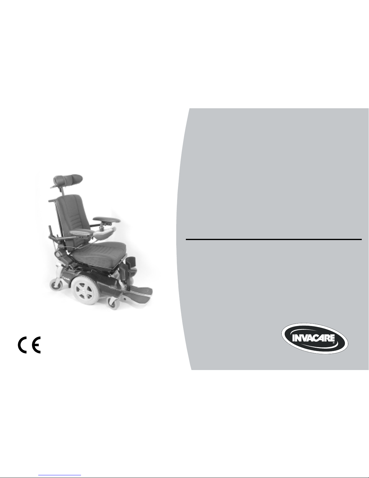
Invacare® Tornado
Electric Wheelchai
r
Operating Instructions
Page 2

2
How can you get in touch with Invacare®?
If you have any questions or need support, please contact your authorised Invacare® Dealer, who has the
necessary know-how and equipment plus the special knowledge concerning your Invacare® product, and
can offer you all-round satisfactory service. Should you wish to contact Invacare® directly, you can reach us
in Europe at the following addresses and phone numbers.
Mobitec Mobilitätshilfen GmbH
Herzog Odilostrasse 101
A-5310 Mondsee
Austria
+43 - 6232 - 55 35 0
Fax: +43 - 6232 - 55 35 4
@: office@mobitec-austria.com
@: austria@invacare.com
WWW: www.mobitec-austria.com
Invacare® n.v.
Autobaan 22
B-8210 Loppem (Brugge)
Belgium
+32 - (0)50 - 83 10 10
Fax: +32 - (0)50 - 83 10 11
@: belgium@invacare.com
WWW: www.invacare.be
Mobitec Rehab AG
Benkenstraße 260
CH-4108 Witterswil
Switzerland
+41 - (0)61 - 48 77 08 0
Fax: +41 - (0)61 - 48 77 08 1
@: office@mobitec-rehab.ch
@: switzerland@invacare.com
WWW: www.mobitec-rehab.ch
Invacare Aquatec
Alemannenstraße 10
88316 Isny
Deutschland
0 75 62 / 7 00 - 251
Fax 08 00 / 6 73 81 72
@: info@invacare-aquatec.de
WWW: www.invacare-aquatec.de
Invacare® A/S
Sdr. Ringvej 39
DK-2605 Brøndby
Danmark
(Kundeservice): +45 - (0)36 - 90 00 00
Fax (Kundeservice): +45 - (0)36 - 90 00 01
@: denmark@invacare.com
WWW: www.invacare.dk
Page 3

3
Invacare® SA
c/ Areny, s/n
Poligon Industrial de Celrà
17460 Celrà (Girona)
ESPAÑA
: +34 - (0)972 - 49 32 00
Fax: +34 - (0)972 - 49 32 20
@: contactsp@invacare.com
WWW: www.invacare.es
Invacare® Poirier SAS
Route de St Roch
F-37230 Fondettes
France
: +33 - (0)247 - 62 64 66
Fax : +33 - (0)247 - 42 12 24
@: contactfr@invacare.com
WWW: www.invacare.fr
Invacare® Ltd
South Road
Bridgend Industrial Estate
Mid Glamorgan - CF31-3PY
United Kingdom
(Customer Service): +44 - (0)1656 - 664 321
Fax (Customer Service): +44 - (0)1656 - 667 532
@: uk@invacare.com
@: eire@invacare.com
WWW: www.invacare.co.uk
Invacare Mecc San s.r.l.
Via Dei Pini, 62
I - 36016 Thiene (VI)
ITALIA
+39 - 0445 - 38 00 59
Fax: +39 - 0445 - 38 00 34
@: italia@invacare.com
WWW: www.invacare.it
Invacare Ireland Ltd.
Unit 5 Seatown Business Campus
Seatown Rd, Swords
County Dublin
Ireland
+353 - 18 10 70 84
Fax: +353 - 18 10 70 85
@: eire@invacare.com
Invacare® AS
Grensesvingen 9
Postboks 6230
N-0603 Oslo
Norge
(Kundeservice): +47 - (0)22 57 95 10
Fax (Kundeservice): +47 - (0)22 57 95 01
@: norway@invacare.com
WWW: www.invacare.no
Page 4

4
Invacare® B.V.
Celsiusstraat 46
NL-6716 BZ Ede
Nederland
: +31 - (0)318 - 69 57 57
Fax: +31 - (0)318 - 69 57 58
@: nederland@invacare.com
WWW: www.invacare.nl
Invacare Portugal, Lda
Rua Estrada Velha, 949
4465-784 Leça do Balio
Portugal
: +351-225105946
Fax: +351-225105739
@: portugal@invacare.com
WWW: www.invacare.pt
Återförsäljare:
Invacare® AB
Fagerstagatan 9
S-163 91 Spånga
Sverige
Tillverkare:
Invacare® Deutschland GmbH
Kleiststraße 49
D-32457 Porta Westfalica
Deutschland
(Kundtjänst): +46 - (0) 8 761 70 90
Fax (Kundtjänst): +46 - (0) 8 761 81 08
@: sweden@invacare.com
@: finland@invacare.com
WWW: www.invacare.se
MÖLNDAL
+46 - (0) 31 – 86 36 00
Fax: +46 - (0) 31 – 86 36 06
@: ginvacare@invacare.com
LANDSKRONA
+46 - (0) 418 – 285 40
Fax: +46 - (0) 418 – 180 89
@: linvacare@invacare.com
OSKARSHAMN
+46 - (0) 491 – 101 40
Fax: +46 - (0) 491 – 101 80
@: oinvacare@invacare.com
Page 5

5
Table of Contents
Chapter Page
1 Introduction 11
1.1 Important symbols in this manual .........................................................................................13
1.2 Important symbols found on the vehicle ..............................................................................14
1.3 Type classification and permissible use...............................................................................15
1.4 Guarantee.................................................................................................................................15
1.5 Indications................................................................................................................................16
1.6 Life expectancy........................................................................................................................16
2 Safety Notes 17
2.1 General Safety Notes ..............................................................................................................17
2.2 Safety Information on Electromagnetic Interference...........................................................20
2.3 Safety Information on Driving and Freewheel Mode............................................................21
2.4 Safety Information on Wheelchairs with a Lifter..................................................................23
2.5 Safety Information on Wheelchairs with Recaro Seats .......................................................24
3 Key features 25
4 Getting in and out of the wheelchair 26
4.1 Remove the standard armrest in order to side transfer ......................................................26
4.2 Raise the parallel sliding armrest / remove the skirtguard (optional) ...............................27
5 Driving 29
5.1 Before driving for the first time..............................................................................................29
5.2 Taking Obstacles.....................................................................................................................30
5.2.1 The ”SureStep“ System ................................................................................................30
Page 6

6
5.2.2
The ”Stability Lock“ System..........................................................................................30
5.2.3 The components of the "SureStep" and the "Stability Lock" system............................31
5.2.4 Maximum obstacle height.............................................................................................31
5.2.5 Safety information when ascending obstacles .............................................................32
5.2.6 Safety information when descending obstacles ...........................................................33
5.2.7 The correct way to overcome obstacles .......................................................................34
5.3 Driving up and down gradients..............................................................................................35
5.4 Parking and stationary............................................................................................................36
6 Pushing the wheelchair in freewheel mode 37
6.1 Disengaging Motors................................................................................................................37
7 The REM 24 SD Remote 38
7.1 Layout of the remote...............................................................................................................38
7.2 ON/OFF diode (status display)...............................................................................................41
7.3 Battery charger display...........................................................................................................41
7.4 Activating / deactivating the immobilizer..............................................................................42
7.5 Using the Buddy buttons with the remote ............................................................................43
7.6 Controlling the wheelchair using the remote .......................................................................44
7.6.1 How a wheelchair with "Indirect Steering" reacts to joystick movements.....................45
7.7 Operating the electric adjustment options ...........................................................................46
7.7.1 Activating adjustment mode..........................................................................................46
7.7.2 Selecting and operating the adjustment option ............................................................47
7.7.3 Changing back to driving mode ....................................................................................48
7.8 Error diagnosis ........................................................................................................................49
7.8.1 Error codes and diagnostic codes ................................................................................50
8 The G80i remote (optional) 52
9 Adjusting the wheelchair to the user's seating posture 53
9.1 Recaro® seats..........................................................................................................................53
Page 7

7
9.2
Adjusting the armrests and the joystick box........................................................................54
9.2.1 Adapting the remote to the length of the user’s arm ....................................................54
9.2.2 Setting the height of the remote ...................................................................................55
9.2.3 Setting the height of the armrests.................................................................................56
9.2.4 Adjusting the width of the armrests ..............................................................................57
9.3 Manually adjusting the seat tilt ..............................................................................................59
9.4 Manually adjusting the backrest............................................................................................61
9.4.1 Adjusting the backrest using the gas pressure spring..................................................61
9.4.1.1 Adjust the backrest using the perforated plate ........................................................62
9.4.2 Flex and Contour seats.................................................................................................63
9.5 The Lifter ..................................................................................................................................64
9.5.1 Explanation of symbols on lifter warning sticker...........................................................65
9.6 Adjusting and removing the tray ...........................................................................................66
9.6.1 Laterally adjusting the tray............................................................................................66
9.6.2 Adjusting the depth of the tray / removing the tray.......................................................67
9.6.3 Swinging the tray away to the side ...............................................................................67
9.7 Child seat (option) ...................................................................................................................69
9.7.1 The headrest of the child seat ......................................................................................69
9.7.1.1 Adjusting the angle / depth of the headrest.............................................................69
9.7.1.2 Adjusting the height of the headrest........................................................................70
9.7.2 The armrests / setting the angle ...................................................................................71
9.7.3 The backrest .................................................................................................................72
9.7.3.1 Adjusting the height of the sliding handles (option).................................................72
9.7.3.2 Adjusting the angle of the backrest electrically .......................................................73
9.7.3.3 Adjusting the angle of the backrest manually..........................................................73
9.7.4 The legrest of the child seat..........................................................................................74
9.7.4.1 Setting the angle of the footrest...............................................................................74
9.7.4.2 Swivelling the footrest upward / removing the legrest.............................................75
9.7.4.3 Adjusting the width of the legrest.............................................................................77
9.7.4.4 Adjusting the length of the legrest ...........................................................................83
9.7.4.5 Adjusting the angle of the legrest ............................................................................84
Page 8

8
10 Adjusting footrests and legrests 85
10.1 Centre-mounted legrests........................................................................................................85
10.1.1 Electric legrest ..............................................................................................................85
10.1.1.1 Lowering the electric legrest completely to assist getting out of the wheelchair.....86
10.1.2 Adjustable legrest .........................................................................................................89
10.1.2.1 Adjusting the angle ..................................................................................................89
10.1.2.2 Adjusting the length of the legrest ...........................................................................90
10.1.2.3 Adjusting the calf plate to the calf width of the user ................................................91
10.1.2.4 Adjusting the angle of the foot plate ........................................................................92
10.2 Laterally mounted legrests.....................................................................................................93
10.2.1 Standard footrest with pre-set angle.............................................................................93
10.2.1.1 Swivelling the footrest outward and/or removing.....................................................93
10.2.1.2 Setting the angle......................................................................................................94
10.2.1.3 Setting the end stop of the footrest .........................................................................96
10.2.1.4 Adjusting the length of the footrest..........................................................................99
10.2.2 Manually height adjustable legrest 90° - 0° ................................................................100
10.2.2.1 Swivelling the legrest outward and/or removing....................................................100
10.2.2.2 Setting the angle....................................................................................................101
10.2.2.3 Setting the end stop of the legrest.........................................................................102
10.2.2.4 Adjusting the length of the legrest .........................................................................105
10.2.2.5 Adjusting the depth of the calf plate ......................................................................106
10.2.2.6 Adjusting the height of the calf plate .....................................................................107
10.2.2.7 Unlocking and swivelling the calf plate backward when alighting .........................108
10.2.2.8 Adjusting the angle adjustable foot plate...............................................................109
10.2.2.9 Adjusting the angle and depth adjustable foot plate .............................................110
10.2.3 Manually height adjustable legrest 80° - 0° with ergonomic length adjustment .........111
10.2.3.1 Swivelling the legrest outward and/or removing....................................................111
10.2.3.2 Setting the angle....................................................................................................112
10.2.3.3 Adjusting the length of the legrest .........................................................................114
10.2.3.4 Adjusting the depth of the calf plate ......................................................................115
Page 9

9
10.2.3.5
Adjusting the height of the calf plate .....................................................................116
10.2.3.6 Unlocking and swivelling the calf plate backward when alighting .........................117
10.2.3.7 Adjusting the angle adjustable foot plate...............................................................118
10.2.3.8 Adjusting the angle and depth adjustable foot plate .............................................119
10.2.4 Electrically height adjustable legrest 80° - 0° with ergonomic length adjustment ......120
10.2.4.1 Swivelling the legrest outward and/or removing....................................................120
10.2.4.2 Setting the angle....................................................................................................121
10.2.4.3 Adjusting the length of the legrest .........................................................................122
10.2.4.4 Adjusting the depth of the calf plate ......................................................................123
10.2.4.5 Adjusting the height of the calf plate .....................................................................124
10.2.4.6 Unlocking and swivelling the calf plate backward when alighting .........................125
10.2.4.7 Adjusting the angle adjustable foot plate...............................................................126
10.2.4.8 Adjusting the angle and depth adjustable foot plate .............................................127
11 Electrical System 128
11.1 Electronics Protection System ............................................................................................128
11.1.1 The main fuse .............................................................................................................129
11.2 Batteries .................................................................................................................................130
11.2.1 What you need to know about batteries .....................................................................130
11.2.2 Charging the batteries ................................................................................................132
11.2.3 Removing and fitting batteries ....................................................................................134
11.2.3.1 Removing the batteries..........................................................................................135
11.2.3.2 How to handle damaged batteries correctly ..........................................................142
12 Care and maintenance 143
13 Repair Instructions 146
13.1 Repairing a flat tyre ...............................................................................................................146
13.1.1 Repairing punctures (drive wheel with conventional motor and pneumatic tyres) .....147
14 Transport 151
Page 10

10
14.1
Transferring the wheelchair to a vehicle.............................................................................151
14.2 Use of the wheelchair as a seat in a vehicle.......................................................................153
14.2.1 How the wheelchair is anchored in a vehicle for use as a vehicle seat .....................155
14.2.2 How the user is secured within the wheelchair...........................................................156
14.3 Securing the wheelchair for transport without passengers .............................................159
15 Refurbishment 160
16 Disposal 161
17 Technical Specifications 162
18 Inspections Performed 166
Page 11

11
1 Introduction
Dear user,
First we would like to thank you for purchasing our product! We hope that you will have a great deal
of pleasure with your new power chair.
This operating manual contains important information and notes about:
• Safety
• Operation
• Care and maintenance
Please take care to read the operating manual thoroughly before starting out on your first
journey.
This wheelchair has been constructed for a large circle of users with different requirements.
The decision whether the model is suitable for the user may only be taken by medical specialists
with appropriate expertise.
Invacare® or their statutory representatives can accept no liability in cases in which the wheelchair
has not been adapted to suit the users’ handicaps.
Some maintenance and settings can be performed by the user or his/hers attendants. Certain
adjustments do however require technical training and may only be carried out by your Invacare®
specialist dealer. Damages and errors caused by nonobservance of the operating manual or as a
result of incorrect maintenance are excluded from all guarantees.
Page 12

12
This manual contains copyrighted information. This manual may not be reproduced or reprinted
either partly or completely without previous written consent from Invacare® or its statutory
representatives. We reserve the right to make any necessary alterations on the grounds of
technical improvements.
Page 13

13
1.1 Important symbols in this manual
WARNING!
This symbol warns you of danger!
• Always follow these instructions to avoid injury to the user or damage to the product!
EXPLOSION HAZARD!
This symbol warns you of an explosion hazard, which, for example, can be caused by
excessive tyre pressure in a pneumatic tyre!
• Always follow the instructions to avoid injury to the user or damage to the product!
BURN HAZARD!
This symbol warns you of burns due, for example, to leaking battery acid!
• Always follow the instructions to avoid injury to the user or damage to the product!
NOTE:
This symbol identifies general information which is intended to simplify working with your product
and which refers to special functions.
Requirements:
• This symbol identifies a list of various tools, components and items which you will need in
order to carry out certain work.
READ WELL BEFORE OPERATION!
This symbol advises you to read information carefully.
Page 14
14
1.2 Important symbols found on the vehicle
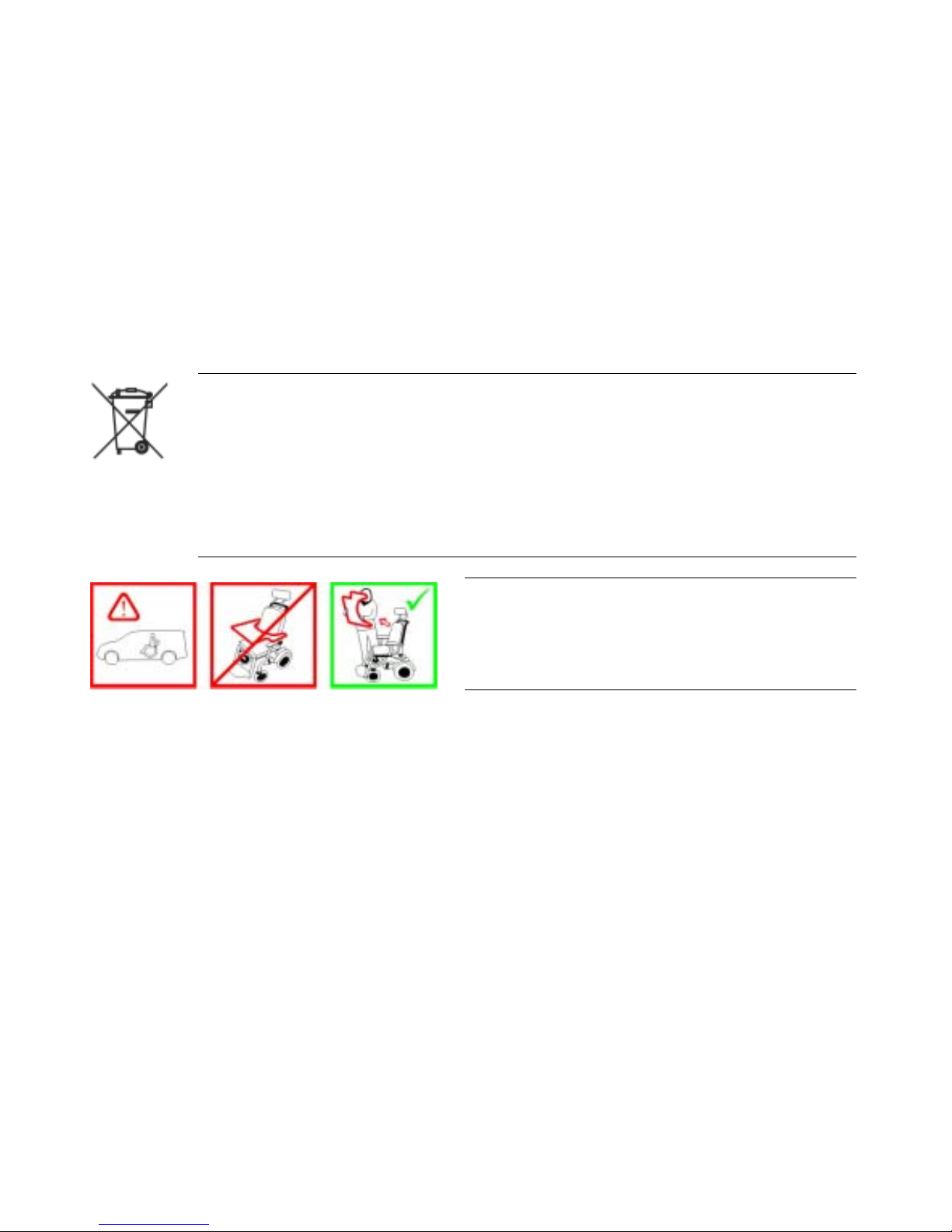
This product has been supplied from an environmentally aware manufacturer that
complies with the Waste Electrical and Electronic Equipment (WEEE) Directive
2002/96/CE. This product may contain substances that could be harmful to the
environment if disposed of in places (landfills) that are not appropriate according to
legislation.
• The 'crossed out wheelie bin' symbol is placed on this product to encourage you to
recycle wherever possible.
• Please be environmentally responsible and recycle this product through your recycling
facility at its end of life.
If the electric wheelchair is fitted with a table, it is
imperative that it is removed and safely stowed
when transporting the wheelchair in a vehicle!
Page 15

15
1.3 Type classification and permissible use
This vehicle was designed for persons whose ability to walk is impaired, but who are still physically
and mentally able to operate an electric vehicle. It has been classified according to EN 12184 as a
class B mobility product (for indoor and outdoor areas). It is therefore compact and agile enough
for indoor areas, but also able to overcome many obstacles in outdoor areas.
You can find exact information on speed, turning radius, range, safe climbing ability, maximum
obstacle height and permissible operating conditions in chapter "Technical Specifications"
starting from page 162.
Please also pay attention to all safety information in chapter "Safety Notes" starting from page 17.
The vehicle was successfully tested according to German and international standards as to its
safety. It was also tested successfully according to EN60529 IPX4 as to its resistance to spray
water, and is therefore well suited for typical middle European weather conditions. When equipped
with an appropriate lighting system, the vehicle is suitable for use on public roads.
1.4 Guarantee
The terms and conditions of the guarantee are part of the general terms and conditions particular to
the individual countries in which this product is sold.
Page 16

16
1.5 Indications
The use of this mobility product is recommended for the following indications:
The inability or a greatly restricted ability to walk within the scope of the basic requirement to be
able to move within one’s own four walls. The need to leave the dwelling place in order to get some
fresh air during a short walk or to reach those places generally to be found at close distance to the
dwelling and where everyday business is carried out.
Provision of electric wheelchairs for interior and exterior areas is advisable if the use of handoperated wheelchairs is no longer possible on account of the disability, yet proper operation of an
electromotive drive unit is still practicable.
1.6 Life expectancy
We estimate a life expectancy of five years for this product, provided it is used in strict accordance
with the intended use as set out in this document and all maintenance and service requirements
are met. The estimated life expectancy can be exceeded if the product is carefully used and
properly maintained, and provided technical and scientific advances do not result in technical
limitations. The life expectancy can also be considerably reduced by extreme or incorrect usage.
The fact that we estimate a life expectancy for this product does not constitute an additional
warranty.
Page 17

17
2 Safety Notes
READ WELL BEFORE OPERATION!
2.1 General Safety Notes
Danger of injury if mobility device is used in any other way than the purpose described in
this manual!
• Only ever use the mobility device in accordance with the instructions in this User's Manual
(see chapter "Type classification and permissible use" on page 15).
• Pay strict attention to the safety information.
Danger of injury if the mobility device is driven when ability to operate a vehicle is
impaired by medication or alcohol!
• Never drive the mobility device under the influence of medication or alcohol. If necessary, the
mobility device must be operated by an attendant who is physically and mentally able.
Danger of damage or injury if mobility device is accidentally set into motion!
• Switch the mobility device off before you get in, get out or handle unwieldy objects.
• When the drive is disengaged, the brake inside the drive is deactivated. For this reason,
pushing the mobility device by an attendant is only recommended on flat surfaces, never on
gradients. Never leave your mobility device on a gradient with its motors disengaged. Always
re-engage the motors immediately after pushing the mobility device (see chapter "Pushing the
wheelchair in freewheel mode" on page 37).
Page 18

18
Danger of injury if the mobility device is switched off while driving, for example by
pressing the On/Off Button or disconnecting a cable, due to it coming to an abrupt, sharp
stop!
• If you have to brake in an emergency, simply release the joystick which will bring you to a halt.
(refer to the joystick operating manual for more information).
Danger of injury when transferring mobility device to a vehicle for transport with the
occupant seated in it!
• It is always better to transfer the mobility device to a vehicle without the occupant seated in it.
• If the mobility device needs to be loaded up a ramp together with its driver, ensure that the
ramp does not exceed the maximum safe slope (see chapter "Technical Specifications" from
page 162).
• If the mobility device does need to be loaded using a ramp which exceeds the maximum safe
slope (see chapter "Technical Specifications" from page 162), then you must use a winch. An
attendant can safely monitor and assist the loading process.
• As an alternative you can use a platform lift. Ensure that the total weight of the mobility device
including the user does not exceed the maximum permissible weight for the platform lift or
winch if you are using.
Danger of injury if maximum permissible load is exceeded!
• Do not exceed the maximum permissible load (see chapter "Technical Specifications" from
page 162).
• The mobility device is only designed for use by a single occupant whose maximum weight
does not exceed the maximum permissible load of the chair. Never use the mobility device to
transport more than one person.
Page 19

19
Danger of injury due to wrong lifting or dropping of heavy components!
• When maintaining, servicing or lifting any part of your mobility device, take into account the
weight of the individual components especially the batteries. Be sure at all times to adopt the
correct lifting posture and ask for assistance if necessary.
Danger of falling out of the mobility device.
• Do not slide forward on the seat, do not lean forward between your knees, do not lean
backwards out over the top of the backrest, for example to reach an object.
• If a posture belt is installed, it should be correctly adjusted and used each time you use the
mobility device.
• When transferring to a different seat, position the mobility device as close as possible to the
new seat.
Danger of injury by moving parts!
• Make sure that no injury is incurred by moving parts of the mobility device, like wheels or one
of the Lifter Modules (if fitted), especially when children are around.
Danger of fire or breaking down due to electric devices being connected!
• Do not connect any electric devices to your mobility device that are not expressly certified by
Invacare® for this purpose. Have all electrical installations done by your authorised Invacare®
Dealer.
Page 20

20
2.2 Safety Information on Electromagnetic Interference
This electric vehicle was successfully tested in accordance with International standards as to its
compliance with Electromagnetic Interference (EMI) Regulations. However, electromagnetic fields,
such as those generated by radio and television transmitters, and cellular phones, can influence
the functions of electric vehicles. Also, the electronics used in our vehicles can generate a low level
of electromagnetic interference, which however will remain within the tolerance permitted by law.
For these reasons we ask you to please observe the following precautions:
WARNING: Danger of malfunction due to electromagnetic interference!
• Do not switch on or operate portable transceivers or communication devices (such as radio
transceivers or cellular phones) when the vehicle is switched on.
• Avoid getting near strong radio and television transmitters.
• In case the vehicle should be set in motion unintentionally or the brakes are released, switch
it off immediately.
• Adding electrical accessories and other components or modifying the vehicle in any way can
make it susceptible to electromagnetic interference. Keep in mind that there is no sure way to
determine the effect such modifications will have on the overall immunity of the electronic
system.
• Report all occurrences of unintentional movement of the vehicle, or release of the electric
brakes to the manufacturer.
Page 21

21
2.3 Safety Information on Driving and Freewheel Mode
Danger of injury if the wheelchair tips over!
• Inclines and declines can only be travelled up to the maximum safe slope (see chapter
"Technical Specifications" from page 162).
• Always return the backrest of your seat or the seat tilt to an upright position before ascending
slopes. We recommend that you position the seat backrest and the seat tilt (if fitted) slightly to
the rear before descending slopes.
• Only ever drive downhill at a maximum of 2/3 of the top speed. Avoid abrupt braking or
accelerating on gradients.
• If at all possible, avoid driving on slippery surfaces (such as snow, gravel, ice etc.) where there
is a danger of you losing control over the vehicle, especially on a gradient. If driving on such a
surface is inevitable, then always drive slowly and with the utmost caution.
• Never attempt to overcome an obstacle when on an uphill or downhill gradient.
• Never attempt to drive up or down a flight of steps with your wheelchair.
• When overcoming obstacles, always observe the maximum obstacle height (see chapter
"Technical Specifications" from page 162 and information about overcoming obstacles in
chapter "Taking Obstacles" from page 30).
• Avoid shifting your centre of gravity as well as abrupt joystick movements and changes of
direction when the wheelchair is in motion.
• Never use the wheelchair to transport more than one person.
• Do not exceed the overall maximum permissible load or the maximum load per axle (see
chapter "Technical Specifications" on page 162).
• Note that the wheelchair will brake or accelerate if you change the Driving Mode whilst the
wheelchair is in motion.
Page 22

22
Danger of breaking down in adverse weather conditions, i.e. extreme cold, in an isolated
area!
• If you are a user with severely limited mobility, we advise that in the case of adverse weather
conditions DO NOT attempt a journey without an accompanying attendant!
Danger of injury if your foot slides off the footrest and gets caught underneath the
wheelchair when it is in motion!
• Make sure each time before you drive the wheelchair that your feet are squarely and securely
in place on the footplates, and that both legrests are properly locked into place.
Danger of injury if you collide with an obstacle when driving through narrow passages
such as doorways and entrances!
• Drive through narrow passages in the lowest driving mode and with due caution.
If your electric wheelchair has been fitted with angle-adjustable legrests, there is a danger
of personal injury and damage to the wheelchair if you drive the wheelchair with the
legrests raised!
• To avoid unwanted displacement of the wheelchair centre of gravity to the front (especially
when travelling downhill) and in order to avoid damage to the wheelchair, angle-adjustable
legrests must always be lowered during normal travelling.
Page 23

23
2.4 Safety Information on Wheelchairs with a Lifter
IMPORTANT - IF YOUR WHEELCHAIR IS EQUIPPED WITH A LIFTER:
Danger of injury if the wheelchair tips over!
• Never exceed the maximum permissible load (see chapter "Technical Specifications" from
page 162)!
• Avoid dangerous driving situations when the lifter is in a raised position, such as trying to
overcome obstacles like kerbs or driving up or down steep gradients!
• Never lean out of the seat when the lifter is raised!
• Inspect the lifter module at least once a month to make sure the automatic speed reduction
function, which reduces the speed of the wheelchair when the lifter is raised, is working
properly (see chapter "Fehler! Verweisquelle konnte nicht gefunden werden." from page
Fehler! Textmarke nicht definiert.)! Notify your authorised dealership immediately if it is not
working properly!
Danger of injury by moving parts!
• Never let objects get caught in the space underneath a raised lifter!
• Make sure that neither you nor anyone else is injured by placing hands, feet other body
extremities under the raised seat!
Danger of malfunction of the Lifter Module!
• Inspect the lifter module at regular intervals to make sure there are no foreign objects or
visible damage, and to make sure the electric plugs are firmly inserted into their sockets!
WARNING: Danger of injuries and damage to the wheelchair can result if the wheelchair is
lifted up or carried by the seat! The lifter motor can slip out of its fixation under the seat!!
• Never attempt to lift the wheelchair by the seat, only by its frame!
Page 24
24
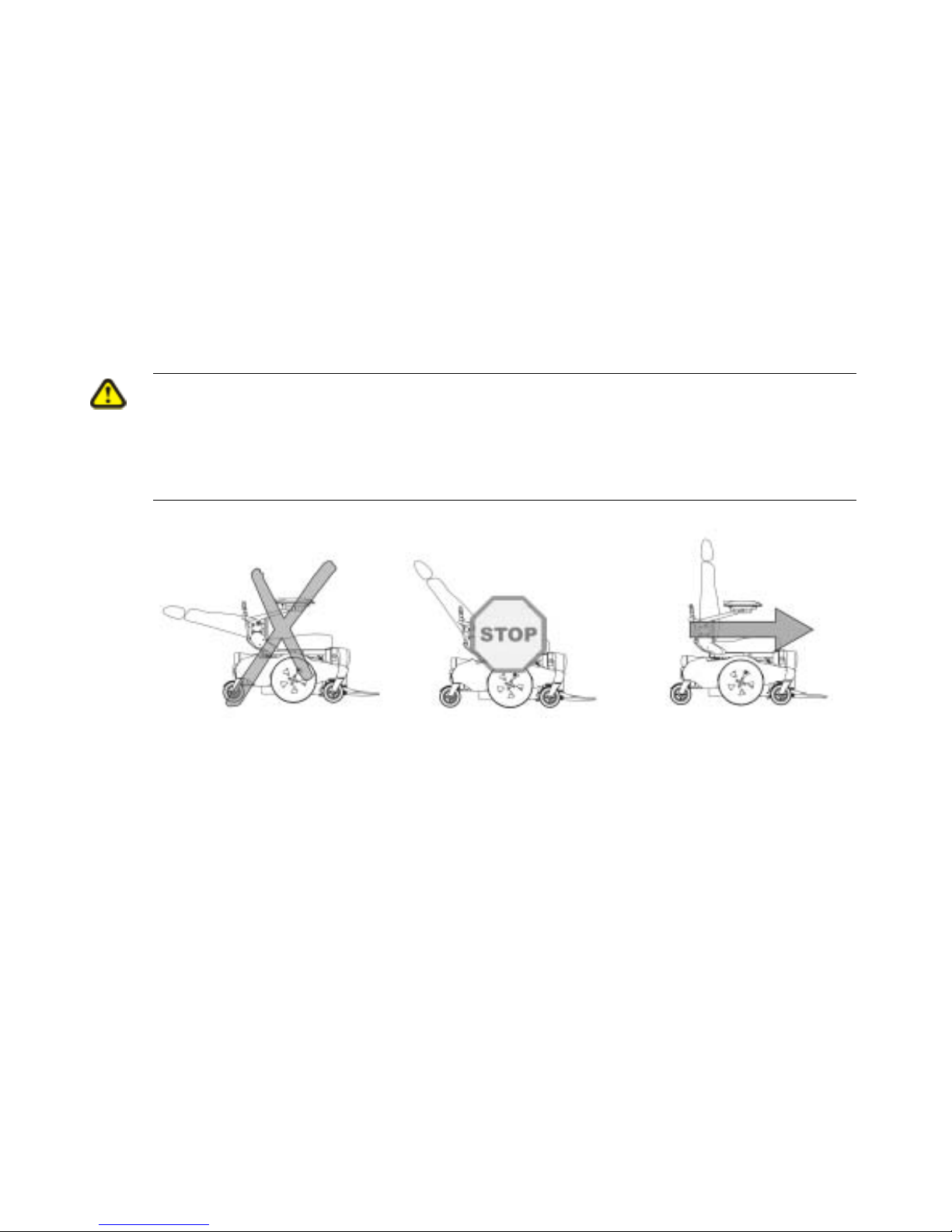
2.5 Safety Information on Wheelchairs with Recaro Seats
Danger of injury if the wheelchair tips over!
The centre of gravity of a Recaro seat is higher than that of other seats. The Recaro seat is
also heavier than other seating systems. The backrests of RECARO seats can be leaned
back 90°. For these reasons there is an increased risk of tipping over!
• Never lean the backrest backward more than 30° degrees, and never exceed 15° when driving
the wheelchair!
More than 30° 15°-30° 0°-15°
NEVER!! Standstill! Driving
Page 25
25
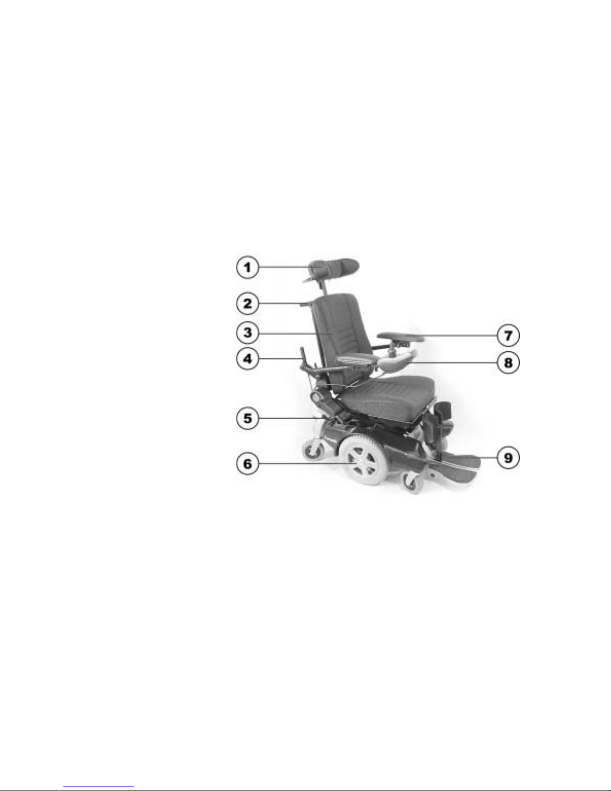
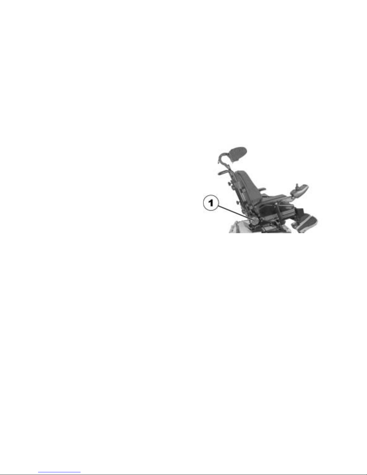
3 Key features
1) Headrest (release
handles for adjustment
purposes are to be found
behind the headrest)
2) Sliding handle
3) Backrest
4) Knob for adjusting the
angle of the armrest
5) Releasing handle
6) Drive wheel
7) Armrest
8) Remote
9) Legrest
Page 26
26
4 Getting in and out of the wheelchair
Important information when side transferring in and out of the wheelchair
In order to side transfer it is necessary for the armrest to either be raised or removed completely
depending on the model. A skirtguard can be installed as an option in connection with the
parallel sliding armrest. This is attached in the same way as the standard armrest and must also
be removed when transferring.
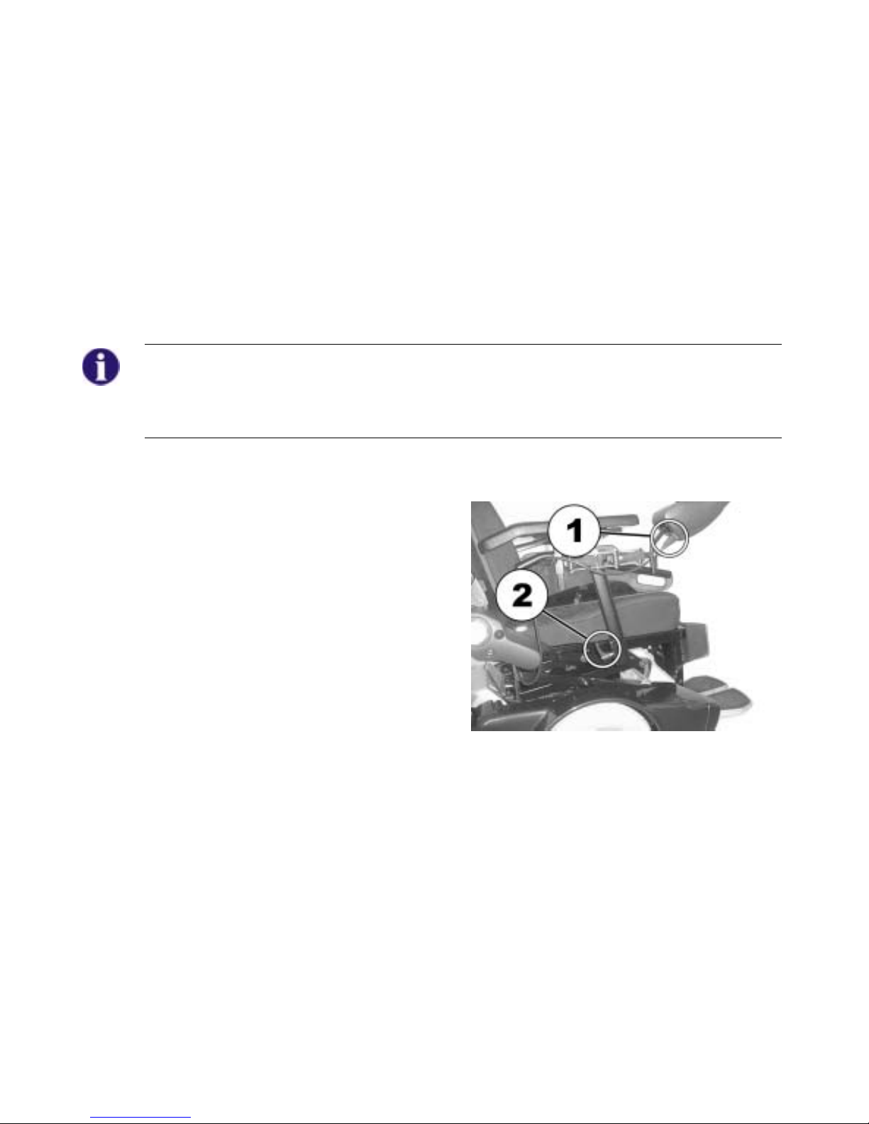
4.1 Remove the standard armrest in order to side transfer
Removing the armrest:
• Detach the remote cable (1) from the remote.
• Loosen the release handle.
• Pull the side frame out of the receptacle.
Page 27
27
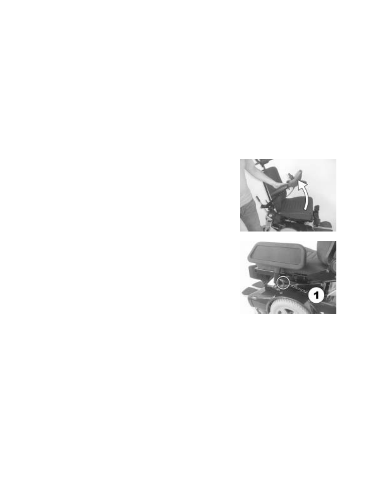
4.2 Raise the parallel sliding armrest / remove the skirtguard
(optional)
Swivel up armrest
• Swivel armrest up to access from the side.
Removing the Skirtguard (option) for access:
• Loosen the release handle (1).
• Pull the Skirtguard out of the receptacle.
Page 28
28
Getting into the wheelchair:
• Position your wheelchair as close as possible to your seat. This might
have to be done by an attendant.
• Switch your wheelchair off.
• Apply the manual wheel lock of your wheelchair (if existing).
• Detach the skirt guard of your wheelchair or swivel it up.
• Now slide into the wheelchair.
Getting out of the wheelchair:
• Drive your wheelchair as close as possible to your seat.
• Switch your wheelchair off.
• Apply the manual wheel lock of your wheelchair (if existing).
• Detach the skirt guard of your wheelchair or swivel it up.
• Now slide onto your new seat.
NOTE:
If you do not have sufficient muscle strength, you should ask other persons for help. Use a
sliding board, if possible.
Page 29

29
5 Driving
NOTE
The maximum load capacity that is stated in the technical data only states that the system is
designed for this mass in total. However, this does not mean that one can sit a person with this
body weight in the wheelchair without restrictions. Attention must be paid to the body
proportions, such as height, weight distribution, abdominal girth, leg and calf girth and seat
depth. These factors have a strong influence on driving features such as tilt stability and traction.
The permissible axle loads in particular must be adhered to (see chapter "Technical
Specifications" as from page 162)! It may possibly be necessary to carry out adaptations to the
seat system.
5.1 Before driving for the first time...
Before you take your first trip, you should familiarise yourself well with the operation of the vehicle
and with all operating elements. Take your time to test all functions and driving modes.
NOTE:
If installed, make sure to properly adjust and use the posture belt each time you use the
wheelchair.
Sitting Comfortably = Driving Safely
Before each trip, make sure that:
You are within easy reach of all operating controls.
• The battery charge is sufficient for the distance intended to be covered.
• The posture belt (if installed) is in perfect order.
Page 30

30
5.2 Taking Obstacles
5.2.1 The ”SureStep“ System
The Invacare® Tornado is fitted with "SureStep" technology. When passing over obstacles, the
front steering wheels are lifted by the torque of the drive wheels. This technology provides excellent
obstacle climbing ability when driving forward, but it is not designed for driving backward. The
maximum obstacle height is considerably reduced when driving backward. For this reason we
recommend you always mount obstacles driving forward.
The approach for overcoming obstacles is fundamentally different for wheelchairs with central drive
and "SureStep" technology than for models with front wheel or rear wheel drive.
5.2.2 The ”Stability Lock“ System
If your wheelchair is fitted with a lifter and this is raised, this will restrict the function of the
"SureStep" system due to the "Stability Lock". The "Stability Lock" increases the tilt stability of the
wheelchair and prevents front wheel spring deflection on the "Walking Beams" when braking or
when descending slopes.
Page 31
31
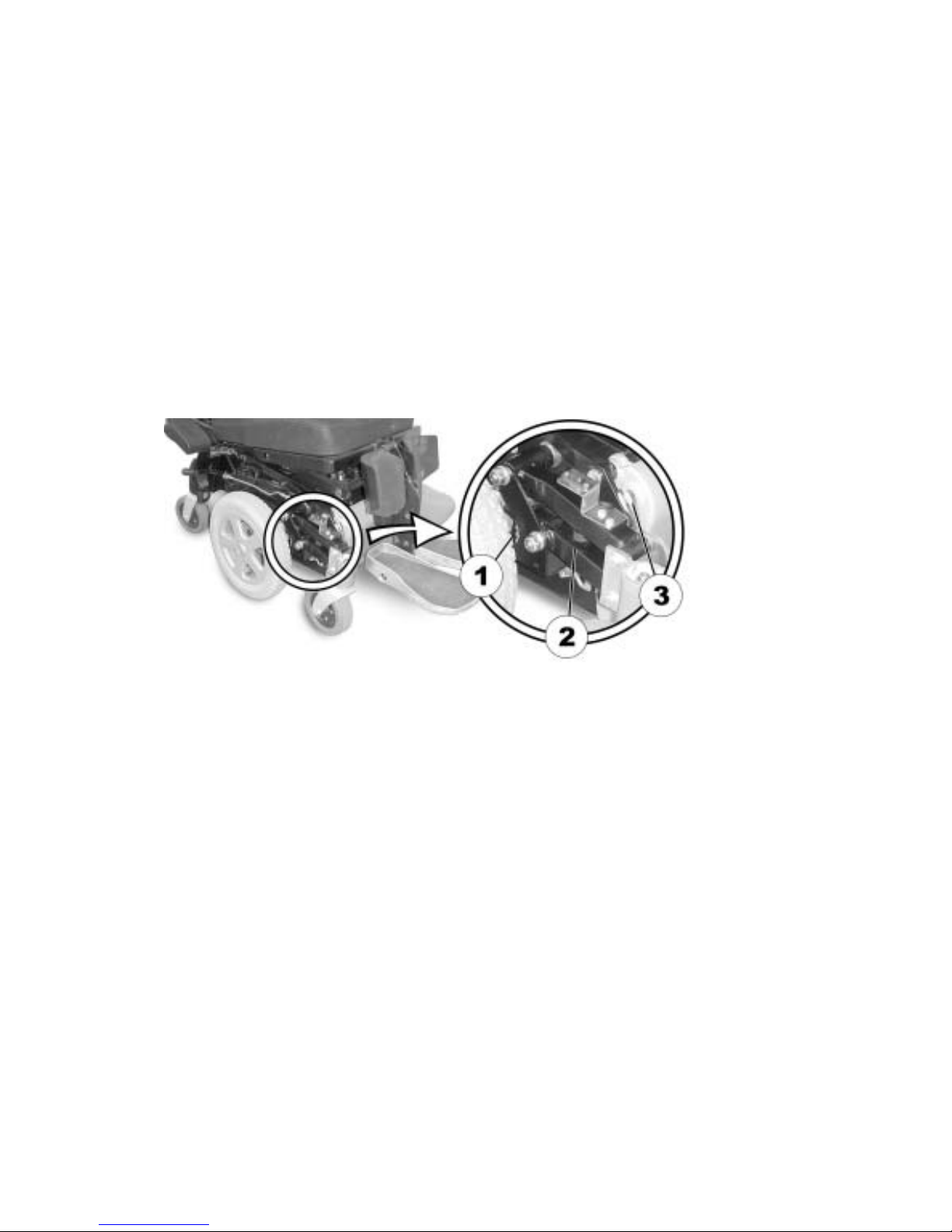
5.2.3 The components of the "SureStep" and the "Stability Lock" system
The picture below shows the “SureStep“ system components after the side panelling has been
removed: (1) Anti-dive spring, (2) walking beam and (3) stability lock.
5.2.4 Maximum obstacle height
Your wheelchair can overcome obstacles and kerbs with the following heights. (only applies to
driving forward).
• Up to 6 cm
Page 32

32
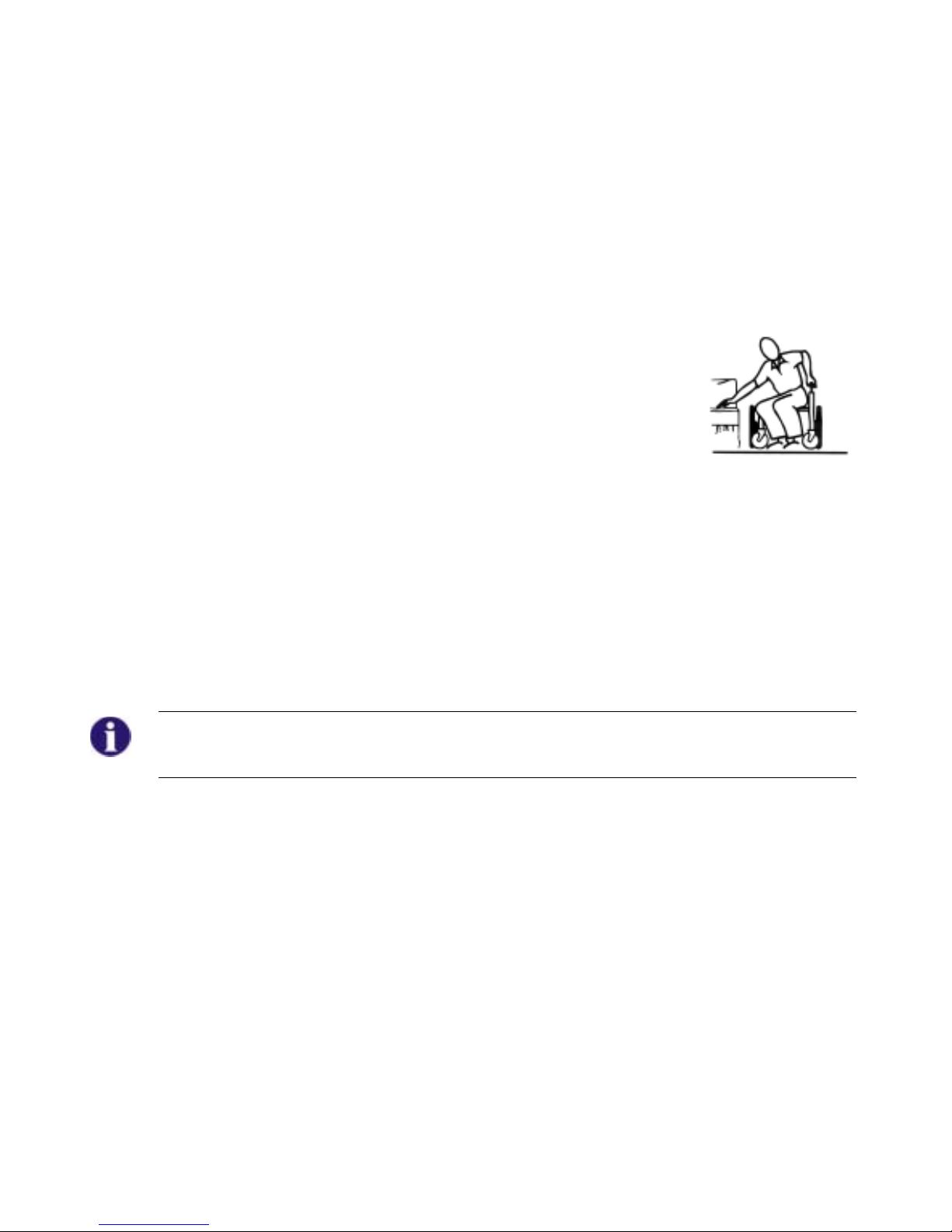
5.2.5 Safety information when ascending obstacles
CAUTION: Danger of Tipping Over!
• Never approach obstacles at an angle but at 90 degrees as shown below.
• Put your backrest into an upright position before climbing an obstacle.
CAUTION: The wheelchair can be damaged if an obstacle is approached at excessive
speed.
• Always approach obstacles at low speed! As soon as the front wheels come into contact with
the obstacle, stop for a short period before driving over the obstacle! Wheelchairs fitted with
centre drive have a special mechanism (Walking Beam) for overcoming obstacles.
Approaching at speed can actually lead to mechanical damage.
Page 33

33
5.2.6 Safety information when descending obstacles
WARNING: In certain situations, e.g. when descending inclines and obstacles, the
wheelchair user could slip off the seat.
• Always fasten the restraining belt when descending from inclines and obstacles.
CAUTION: The wheelchair can tip over to the front when descending from an obstacle that
is too high as there can be spring deflection of the front swivel wheels.
• Please pay particular attention to tilt resistance when driving down off an obstacle!
• If available, please set your seat tilt to a greater value than normal!
• The maximum obstacle height refers to ascent as well as descent. Never descend from
obstacles that are higher than those you may ascend!
Page 34

34
5.2.7 The correct way to overcome obstacles
CAUTION: If the lifter is raised, the drive wheels can lose ground contact when
descending from obstacles or driving on an uneven surface! The "Stability Lock"
prevents “Walking Beam“ spring deflection when the lifter is raised!
• Never descend from obstacles when the lifter is raised or drive on an uneven surface!
• In the event of the drive wheels losing ground contact, the lifter must be lowered so that the
drive wheels come into contact with the ground again.
Ascending and descending
The same approach applies to both ascending and descending obstacles:
• Approach the obstacle or the kerb slowly and at a right angle.
• Stop shortly before the front wheels come into contact with the obstacle.
• Check the position of the front wheels. They must be in driving direction
and at right angles to the obstacle.
• Approach slowly and keep at a consistent speed until the rear wheels have
also passed over the obstacle.
Right
Wrong
Page 35

35
5.3 Driving up and down gradients
For information concerning the maximum safe slope, please see chapter "Technical
Specifications" starting on page 162.
WARNING: In certain situations, e.g. when descending inclines and obstacles, the
wheelchair user could slip off the seat.
• Always fasten the restraining belt when descending from inclines and obstacles.
WARNING: Danger of tipping over!
• Only ever drive downhill at a maximum of 2/3 of the top speed. Avoid sudden changes of
direction or abrupt braking when driving on slopes.
• Always return the backrest of your seat or the seat tilt (if adjustable seat tilt is available) to an
upright position before ascending slopes. We recommend that you position the seat backrest
or the seat tilt slightly to the rear before descending slopes.
• Always lower the lifter (if fitted) to its lowest position before ascending or descending a slope.
• Never attempt to ascend or descend a slope on slippery surfaces or where there is a danger
of skidding (such as wet pavement, ice etc).
• Avoid trying to get out of the vehicle on an incline or a gradient.
• Always drive straight in the direction the road or path you are on goes, rather than attempting
to zigzag.
• Never attempt to turn around on an incline or a slope.
Page 36

36
5.4 Parking and stationary
When parking your vehicle or if your vehicle is stationary for a prolonged period:
• Switch the vehicle's power system off (ON-/OFF key).
• Activate your anti-theft lock, if existing.
Information: If the wheelchair has not been driven for a longer period of time, the solid
rubber tyres of the swivel wheels can be pressed flat.
This effect can crop up relatively quickly in the case of higher ambient temperatures. Once the
wheelchair is driven for a certain period of time, the consistent wheel load will re-establish
concentricity.
Page 37

37
6 Pushing the wheelchair in freewheel mode
The motors of the wheelchair are equipped with automatic brakes, preventing that the wheelchair
starts rolling out of control when the joystick box is switched off. When pushing the wheelchair
manually whilst freewheeling, the magnetic brakes must be disengaged.
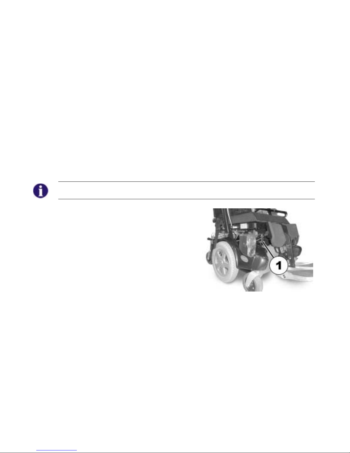
6.1 Disengaging Motors
The lever for disengaging the motors is on the rear right side on the wheelchair chassis.
Danger of the vehicle running away!
• When the motors are disengaged (for push operation whilst freewheeling), the
electromagnetic motor brakes are deactivated! When the vehicle is parked, the levers for
engaging and disengaging the motors must without fail be locked firmly into the "DRIVE"
position (electromagnetic motor brakes activated)!
Disengaging the motors:
• Switch off the remote.
• Simultaneously move the wheelchair gently forward
and backward and push the clutch lever (1)
forward. The motors are disengaged.
Engaging the motors:
• Pull the clutch lever (1) backward. The motors are
engaged.
Page 38

38
7 The REM 24 SD Remote
7.1 Layout of the remote
Upper side
Controls
1) Immobilizer
2) "Activate / scroll through drive
mode" button
3) Horn
4) Left-hand indicator
5) Joystick
6) "Activate adjustment mode"
button
7) ON/OFF button
8) Light
9) Right-hand indicator
10) Hazard warning signal flasher
Page 39
39
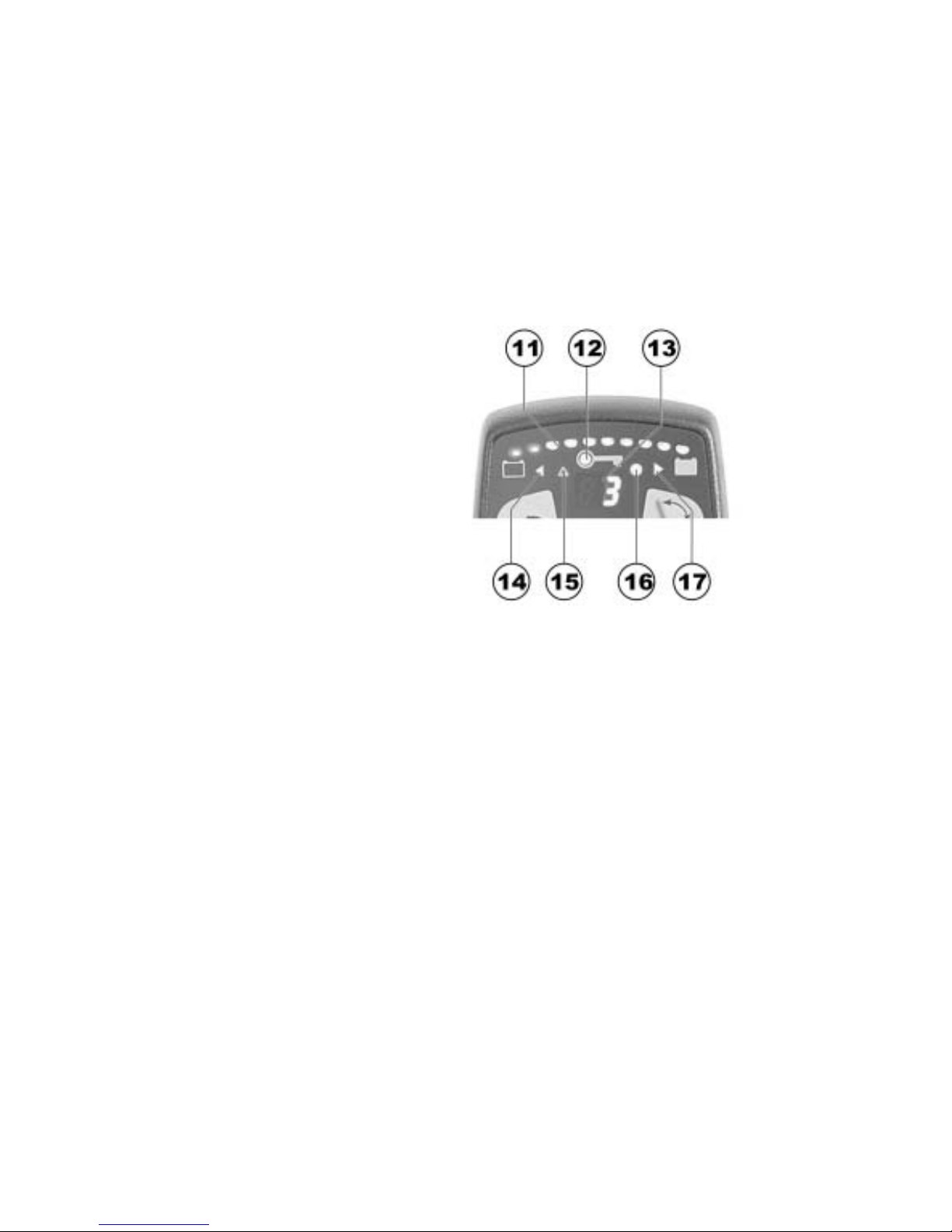
Upper side
Displays
11) Battery charger display
12) Status display (in key symbol)
13) Drive mode display
14) Left-hand indicator display
15) Hazard warning signal flasher
display
16) Light display
17) Right-hand indicator display
Page 40

40
Underside
1) Charger socket
2) Programming socket
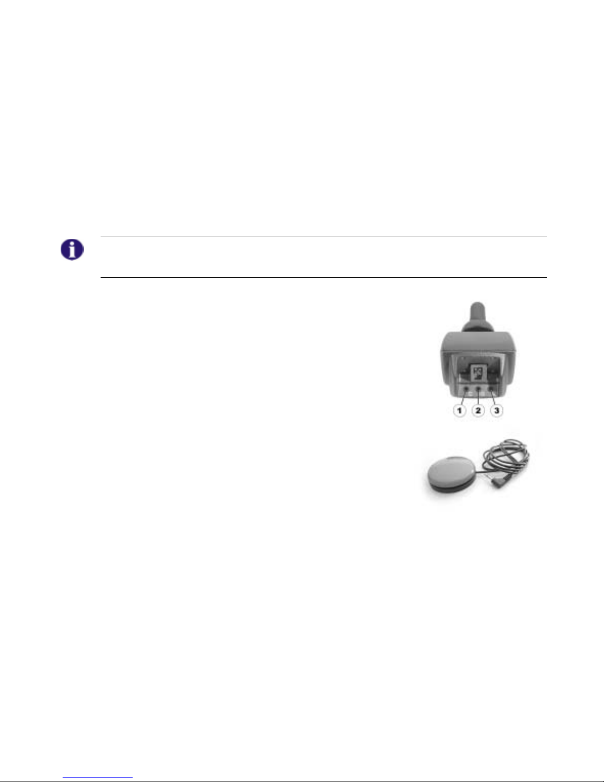
Rear panel
1) Socket for Buddy button 1 (corresponds to "Activate /
scroll through drive mode" button).
2) Socket for Buddy button 2 (corresponds to "ON/OFF"
button)
3) Socket for Buddy button 3 (corresponds to "Activate /
scroll through adjustment mode" button).
4) Socket for bus cable
Page 41

41
7.2 ON/OFF diode (status display)
INFORMATION
The ON/OFF diode (in key symbol) also serves as status or error message display. For error
codes please see chapter "Error codes and diagnostic codes" on page 50.
7.3 Battery charger display
• All diodes illuminated: Full range
• Only red diodes illuminated:
Reduced range
• Both red diodes flashing:
Very low range
• Only one red diode flashing:
Battery on reserve = Charge batteries straight away
Battery charger display
INFORMATION
Protection against total discharge: The electronic system automatically shuts actuation down
after a certain travel time on reserve battery and the wheelchair comes to a standstill.
Page 42

42
7.4 Activating / deactivating the immobilizer
Activating the immobilizer
• Switch on the remote.
• Use the end of the magnetic key (Invacare® Logo) to move over the
sensor area (1) on the remote (key symbol). The horn will sound
briefly once. The remote shuts down automatically. The immobilizer
is activated.
Deactivating the immobilizer
• Switch on the remote. The status display will flash red slowly.
• Use the end of the magnetic key (Invacare® Logo) to move over the
sensor area (1) on the remote (key symbol).
Immobilizer
Magnetic key
Page 43
43
7.5 Using the Buddy buttons with the remote
What is a Buddy button?
A Buddy button is an additional sensing device that can be used to activate a remote function.
The sockets for Buddy buttons are to be found at the rear of the remote.
1) Socket 1 (corresponds to the ""Activate / scroll through drive
mode"" button).
2) Socket 2 (corresponds to the "ON/OFF" button)
3) Socket 3 (corresponds to the " Activate / scroll through
adjustment mode" button).
Page 44

44
7.6 Controlling the wheelchair using the remote
• Switch on the remote (ON/OFF button). The displays on the remote will illuminate. The
wheelchair is ready to drive.
• Set the drive level (“drive level“ button see "Layout of the remote" on page 38).
• Speed stage 1 (slow) to 5 (fast) is shown on the drive level display.
Can the electronic system programming be adapted?
The electronic controller is programmed with standard values during manufacture. Your
Invacare® dealer can carry out programming tailored to fit your requirements.
WARNING: Any alteration to the drive programme can influence vehicle handling and the
tipping stability of the electric vehicle!
• Alterations to the drive programme may only be carried out by trained Invacare® dealers!
• Invacare® supplies all electric vehicles from the factory with a standard drive programme.
Invacare® can only assume a warranty for the safe vehicle handling of the electric vehicle –
in particular tipping stability - for this standard drive programme!
Will the wheelchair not drive after switching on?
Check the drive-away lock (see chapter "Activating / deactivating the immobilizer " on page
42) and the status bar indicator (see chapter "ON/OFF diode (status display)" on page 41.).
Page 45

45
7.6.1 How a wheelchair with "Indirect Steering" reacts to joystick movements.
"Indirect Steering" occurs by individually applying power to the drive wheels, and is found on
wheelchairs with front, rear and middle wheel drive.
Travel direction
The further the joystick is moved in a
particular direction, the more
dynamically the wheelchair reacts.
Note:
To brake quickly, simply let go of the joystick. It will then automatically return to the middle
position. The wheelchair will brake.
Page 46

46
7.7 Operating the electric adjustment options
Electric adjustment options, like electric legrests or an electric backrest, are operated by using the
joystick.
7.7.1 Activating adjustment mode
• Press the "activate adjustment mode" button (A). The remote
switches to the adjustment mode last used. The driving mode
display (B) switches to the appropriate symbol (one of the
symbols shown below). The factory setting for controls is to
display all symbols, irrespective of whether certain adjustment
options are available or not! Your dealer can carry out individual
modification of this setting.
Seat tilt Backrest Left legrest Right legrest Both legrests Lifter
Page 47

47
Information:
When using the REM 24 SD remote it is not necessary – as on previous remote versions – to
push the joystick forward in order to access the adjustment mode. It is sufficient to operate the
adjustment mode button just once.
If the remote has been programmed appropriately, further modes can be accessed by repeatedly
pressing the adjustment mode button, i.e. light mode or ECU mode (environment control unit).
The standard REM 24 SD programming only supports the adjustment function. Please speak to
your Invacare dealer if you have any questions in this respect.
7.7.2 Selecting and operating the adjustment option
• Move the joystick to the left or right = Select adjustment
option on the submenu (A).
• Move the joystick forward/backward = Operate adjustment
option (B).
Page 48

48
7.7.3 Changing back to driving mode
• Briefly press the "Activate / scroll through driving mode" button
(A). The remote switches back to the driving mode last used.
The driving mode display indicates the drive level (B).
Page 49

49
7.8 Error diagnosis
In the event that the electronics should show signs of failure, please consult the following
troubleshooting guide in order to locate the error.
INFORMATION
Before beginning with the diagnosis, please ensure that the drive electronics are switched on.
If the status display is OFF:
Please check whether the drive electronics are SWITCHED ON.
Please check whether all cables have been connected correctly.
Please ensure that the batteries are not discharged.
If the status display is FLASHING:
Please count the number of flashing sequences and move on to the next section.
If the red diodes on the battery charger display and the status display are FLASHING,
Drive mode display shows a horizontal bar:
Battery discharged. Please charge the battery.
Page 50

50
7.8.1 Error codes and diagnostic codes
The drive electronics are capable of rectifying some errors automatically. In this case the status
display will cease to flash. Please switch the remote on and off several times. Wait approx. 5
seconds each time before switching the remote on again. If this does not rectify the error, locate
the error using the flash codes shown below.
FLASH
CODE
FAULT IMMEDIATE MEASURE FURTHER HELP
1
Module defective. -
• Contact your dealer or
wheelchair provider.
2
Lifter raised or
lowered too far (seat
not at driving height)
If lifter is raised, lower in
stages until the status
display stops flashing. If
lowered too far, raise lifter
in stages until the status
display stops flashing. If at
all possible, only drive
when the seat is at driving
height.
• -
Accessory error. -
• Contact your dealer or
wheelchair provider.
3
Fault in left-hand
motor. Connection
loose/defective or
motor defective.
• Check plug-in
connections.
• Replace motor
• Contact your dealer or
wheelchair provider.
4
Fault in right-hand
motor. Connection
loose/defective or
motor defective.
• Check plug-in
connections.
• Replace motor
• Contact your dealer or
wheelchair provider.
Page 51

51
FLASH
CODE
FAULT IMMEDIATE MEASURE FURTHER HELP
5
Fault/brake fault on
left-hand motor.
Connection
loose/defective or
motor defective.
• Check plug-in
connections.
• Replace motor
• Contact your dealer or
wheelchair provider.
6
Fault/brake fault on
right-hand motor.
Connection
loose/defective or
motor defective.
• Check plug-in
connections.
• Replace motor
• Contact your dealer or
wheelchair provider.
7
Battery totally
discharged.
Charge battery
• Contact your dealer or
wheelchair provider.
8
Battery voltage too
high.
-
• Contact your dealer or
wheelchair provider.
9 or 10
Faulty data
transmission between
modules.
-
• Contact your dealer or
wheelchair provider.
11
Motors overstressed. Switch remote off and on
again
• -
12
Compatibility
problems between the
modules.
-
• Contact your dealer or
wheelchair provider.
Page 52

52
8 The G80i remote (optional)
NOTE:
You can find a description of the G80i remote in the appropriate Operating Manual.
Page 53

53
9 Adjusting the wheelchair to the user's seating posture
CAUTION: Wheelchair damage and risk of accident! Collisions can occur between the
legrest and the chassis or between the foot plates and the ground in the event of varying
adjustment option combinations! This occurs in particular on wheelchairs with lifter and a
seat angle adjustment range of -10° to +35°!
• When adjusting seat angle, lifter and legrest please ensure that the legrest does not collide
with the wheelchair chassis or the foot plates with the ground.
9.1 Recaro® seats
Recaro® Seats
For more information on a Recaro® seat, please see the separate User Guide that comes with
the Recaro® seat.
Page 54

54
9.2 Adjusting the armrests and the joystick box
9.2.1 Adapting the remote to the length of the user’s arm
Requirements:
• Allen key 3 mm
• Loosen the socket head screw (1).
• Set remote to the desired length by pushing forward
or backward.
• Tighten screw.
Page 55
55
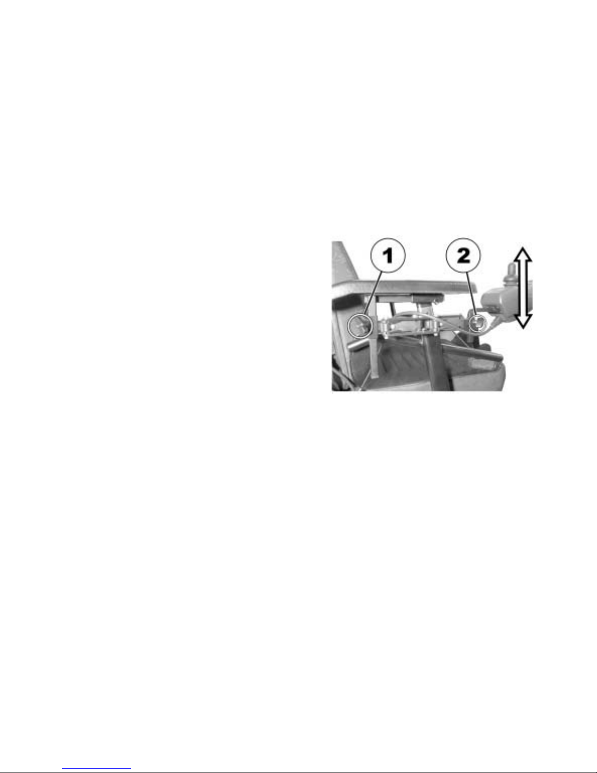
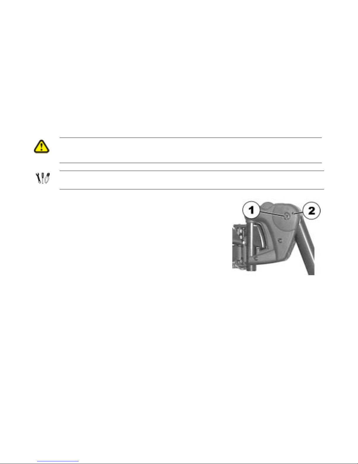
9.2.2 Setting the height of the remote
• Loosen one or both of the wing screws (1 and
2) that allow height adjustment of the joystick
box.
• Adjust the joystick box to the desired height.
• Re-tighten the screw(s).
Page 56

56
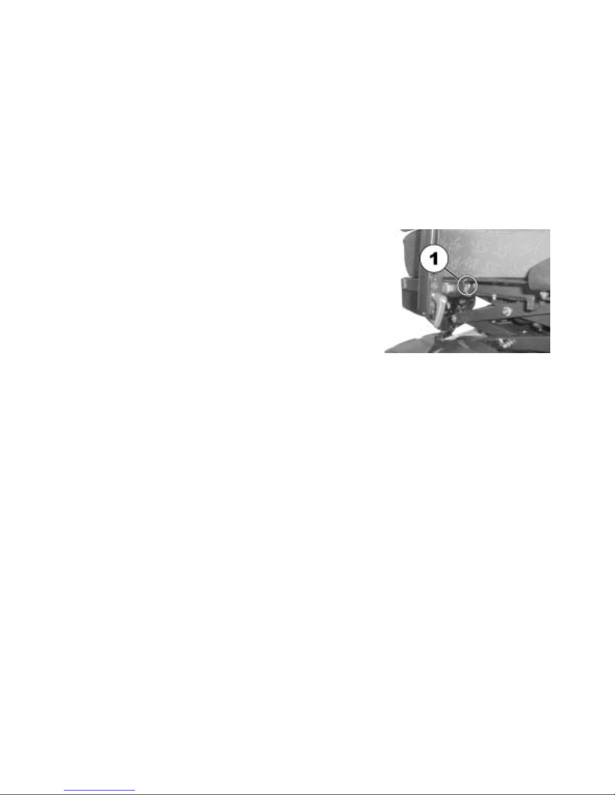
9.2.3 Setting the height of the armrests
• Loosen the bolt (1).
• Set the armrest at the desired height.
• Retighten the bolt.
Page 57

57
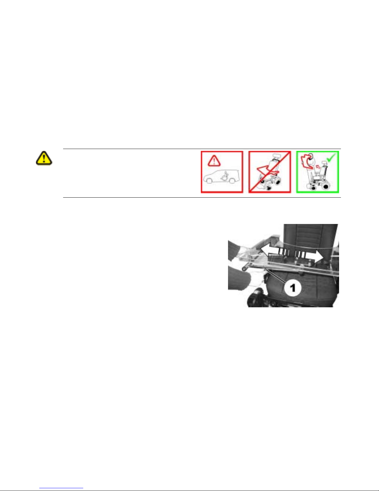
9.2.4 Adjusting the width of the armrests
The distance between the side sections can be adjusted by 5.5 cm on both sides (11 cm in total).
Requirements:
• Allen key 8 mm
Where to find the adjustment screws
The picture below shows the position of the screws (1) that permit adjustment to the width of the
armrests (only the left side is visible in the picture).
Page 58
58
Doing the adjustment
• Loosen screw (1).
• Set the armrest to the desired position.
• Tighten the screw.
• Repeat the procedure for the other armrest.
Page 59
59
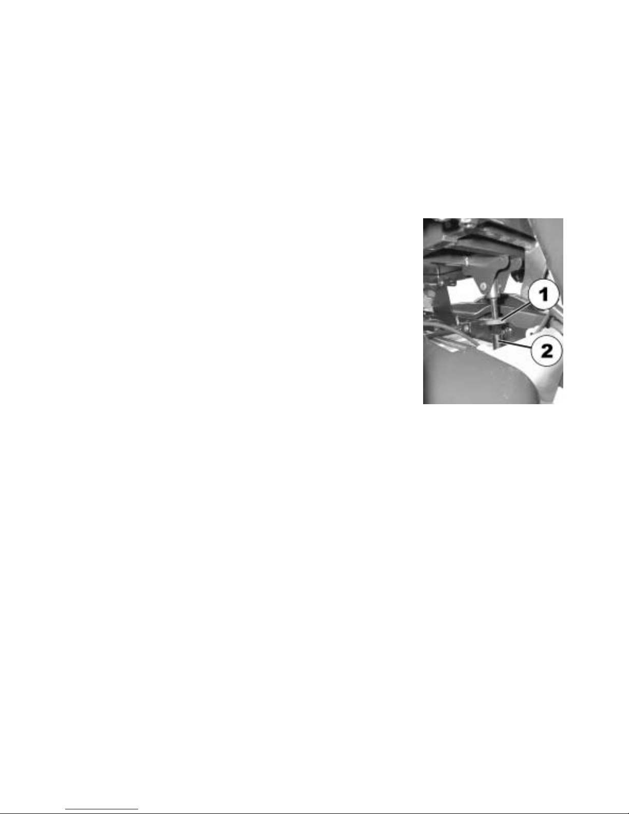
9.3 Manually adjusting the seat tilt
The manual seat angle adjustment has an adjustable range of 0° to 20°.
The seat angle is adjusted by means of a spindle, which is to be found at the front underneath the
seat frame.
When adjusting the seat angle it should be ensured that at least 1cm of the threaded bolt always
remains inside the spindle and is not completely unscrewed from the spindle.
NOTE
It is easier to adjust the angle of the seat when there is nobody sitting in the wheelchair.
The picture on the right shows the position of the
spindle (1) for manual adjustment of the seat angle.
Page 60
60
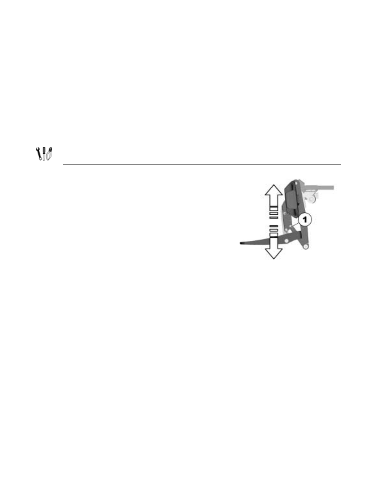
• Loosen the counternut (1) on the spindle.
• Set the seat angle by turning the spindle (2).
• Tighten the counternut.
Page 61
61
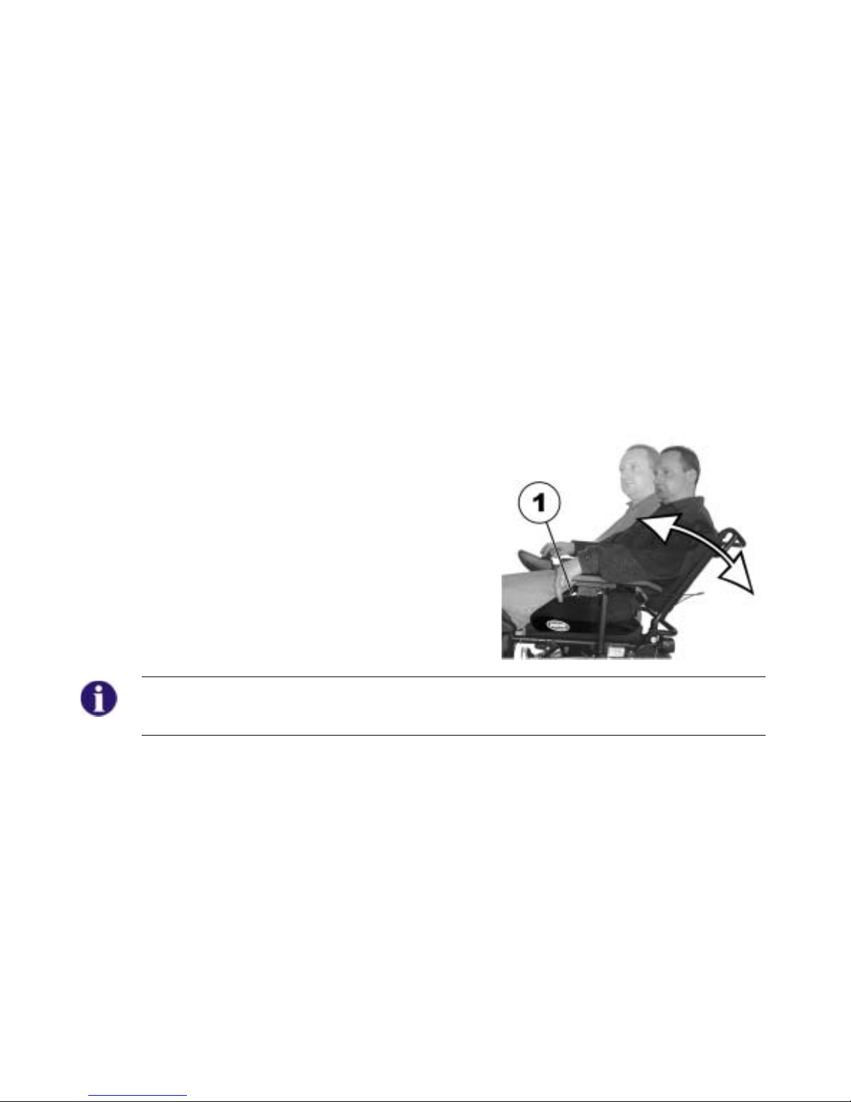
9.4 Manually adjusting the backrest
9.4.1 Adjusting the backrest using the gas pressure spring
The lever for adjusting the backrest is located on the opposite side from the Joystick Box under the
armrest.
Adjusting angle of the backrest
• Pull lever (1) upward.
• Adjust backrest angle by leaning forward or
backward.
• Release the lever again. The backrest is locked at
the desired angle.
NOTE
If the lever is pulled upwards and inwards at the same time, it will latch into a notch at the top.
Push the lever out of the notch to release it, and allow it to be moved down again.
Page 62
62
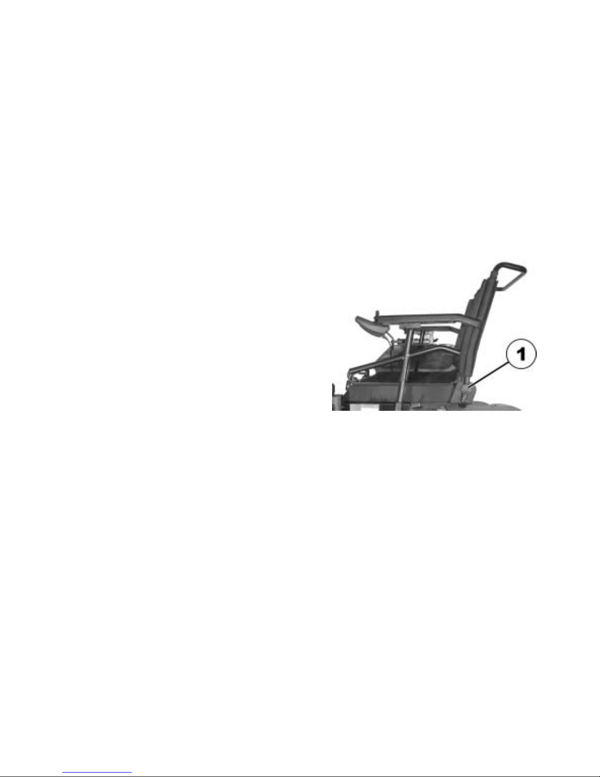
9.4.1.1 Adjust the backrest using the perforated plate
The angle of the backrest has six positions, from -10° to +30°.
• Unscrew the hand screws (1) on both sides.
• The backrest is adjusted by choosing a
combination of one of the two bore holes in the
backrest frame and one of the six bore holes in
the fixing plate.
• Re-position the screws and tighten.
Page 63
63
9.4.2 Flex and Contour seats
• Set the angle by turning the hand wheel (1).
Page 64

64
9.5 The Lifter
The electric lifter is operated via the remote. Please see chapter "Operating the electric
adjustment options" on page 46.
Information regarding operation of the lifter at temperatures of less than 0 °C
Invacare® mobility aids are fitted with safety mechanisms that prevent capacity overload of the
electronic components. At operating temperatures below freezing point this can, in particular,
lead to the lifter actuator being shut down after approx. 1 second operating time.
The lifter can be raised or lowered gradually by repeatedly operating the joystick. In many cases
this generates sufficient heat for the actuator to operate as normal.
Please note – Speed restriction
The lifter is equipped with sensors that reduce the drive speed of the wheelchair as soon as the
lifter is raised or lowered above a certain point.
This is in order to guarantee the tilt stability of the wheelchair or in order to avoid damage to the
legrests.
When speed restriction is activated an appropriate blinking code is displayed on the remote.
Please see chapter "ON/OFF diode (status display)" on page 41 and chapter "Error codes
and diagnostic codes" on page 50.
In order to revert to normal drive speed move the lifter to drive height: Raise the lifter slowly if the
lifter has been lowered. If the lifter has been raised, lower the lifter until the status display stops
blinking.
Page 65

65
9.5.1 Explanation of symbols on lifter warning sticker.
Do not lean out
when the lifter is
raised!
Do not drive up
or down slopes
when the lifter is
raised!
Do not allow any
body parts to get
under a raised
seat!
Never drive with
two people!
Never drive over
uneven surfaces
when the lifter is
raised!
Page 66
66
9.6 Adjusting and removing the tray
CAUTION: Injury hazard or material
damage if an electric wheelchair which is
fitted with a table is transported in a
vehicle!
• If a table is fitted, always remove it before
transporting the wheelchair.
9.6.1 Laterally adjusting the tray
• Loosen the wing-screw (1).
• Adjust the tray towards the left or right.
• Re-tighten wing-screw.
Page 67

67
9.6.2 Adjusting the depth of the tray / removing the tray
• Loosen the wing-screw (1).
• Adjust the table to the desired depth (or remove it entirely).
• Re-tighten the screw.
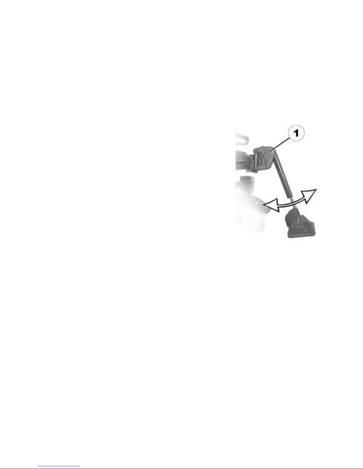
9.6.3 Swinging the tray away to the side
CAUTION! Risk of injury! When the tray is raised it does not lock in place in this position!
• Do not tilt the tray up and leave it leaning in this position.
• Never attempt to drive with the tray tilted up.
• Always lower the tray in a controlled manner.
The tray can be swivelled upwards and pushed to the side as
illustrated to enable getting on and off.
Page 68

68
Page 69

69
9.7 Child seat (option)
The child seat consists of the actual seat, a headrest and a laterally-mounted footrest. The
following describes how these options can be adapted to the sitting posture of the user.
9.7.1 The headrest of the child seat
9.7.1.1 Adjusting the angle / depth of the headrest
• Loosen the release handle (1, 2 or 3).
• Move the headrest to the desired position.
• Tighten the release handle.
Page 70

70
9.7.1.2 Adjusting the height of the headrest
• Loosen the clamping screw (1).
• Move the headrest to the desired height.
• Tighten the clamping screw.
Page 71

71
9.7.2 The armrests / setting the angle
Pre-requisites:
• 13 mm open-ended spanner
The adjusting screw for adjusting the angle of the armrest
is to be found at the rear end of the armrest (A).
• Loosen the counternut (1) using the open-ended
spanner.
• Adjust the limit stop/angle of the armrest by turning the
adjusting screws (2).
• Tighten the counternut.
Page 72

72
9.7.3 The backrest
9.7.3.1 Adjusting the height of the sliding handles (option)
• Loosen the hand wheel (1 or 2).
• Move the sliding handle to the desired position.
• Tighten the hand wheel.
Page 73

73
9.7.3.2 Adjusting the angle of the backrest electrically
As an option the backrest can be adjusted via an electric actuator. Please see chapter "Operating
the electric adjustment options" on page 46.
9.7.3.3 Adjusting the angle of the backrest manually
• Loosen the hand wheel (1).
• Move the backrest into the desired position.
• Tighten the hand wheel.
Page 74
74
9.7.4 The legrest of the child seat
9.7.4.1 Setting the angle of the footrest
Pre-requisites:
• 5 mm Allen key
• Loosen the Allen screws at both ends of the footrest
(1) (only one side is shown in the illustration).
• Move the footrest to the desired position.
• Re-tighten the screws.
Page 75
75
9.7.4.2 Swivelling the footrest upward / removing the legrest
In order to simplify getting into the vehicle and alighting, the footrest can be swivelled upward. The
footrest must also be swivelled upward so that the width of the legrest can be adjusted or the
legrest dismantled.
Pre-requisites:
• 5 mm Allen key
• Loosen the Allen screw (1) on the left end of the
footrest.
• Open the belt with Velcro® fastener (2).
• Swivel the footrest upward.
Page 76

76
• Press the release button (1) and swivel the legrest
outward.
• Remove the legrest in an upward direction.
Page 77
77
9.7.4.3 Adjusting the width of the legrest
Pre-requisites:
• Flat screwdriver
• 5 mm Allen key
• 3 mm Allen key
• 13 mm open-ended spanner
• Swivel the footrest upward and dismantle the
legrest (see section "Swivelling the footrest
upward / " on page 75).
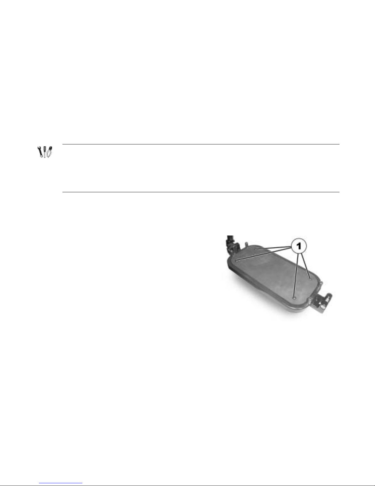
• The footrest has a non-slip rubber mat that is
fastened at the corners by means of four plastic
studs (1). The screws for adjusting the width of the
footrest are to be found underneath the rubber mat.
Page 78
78
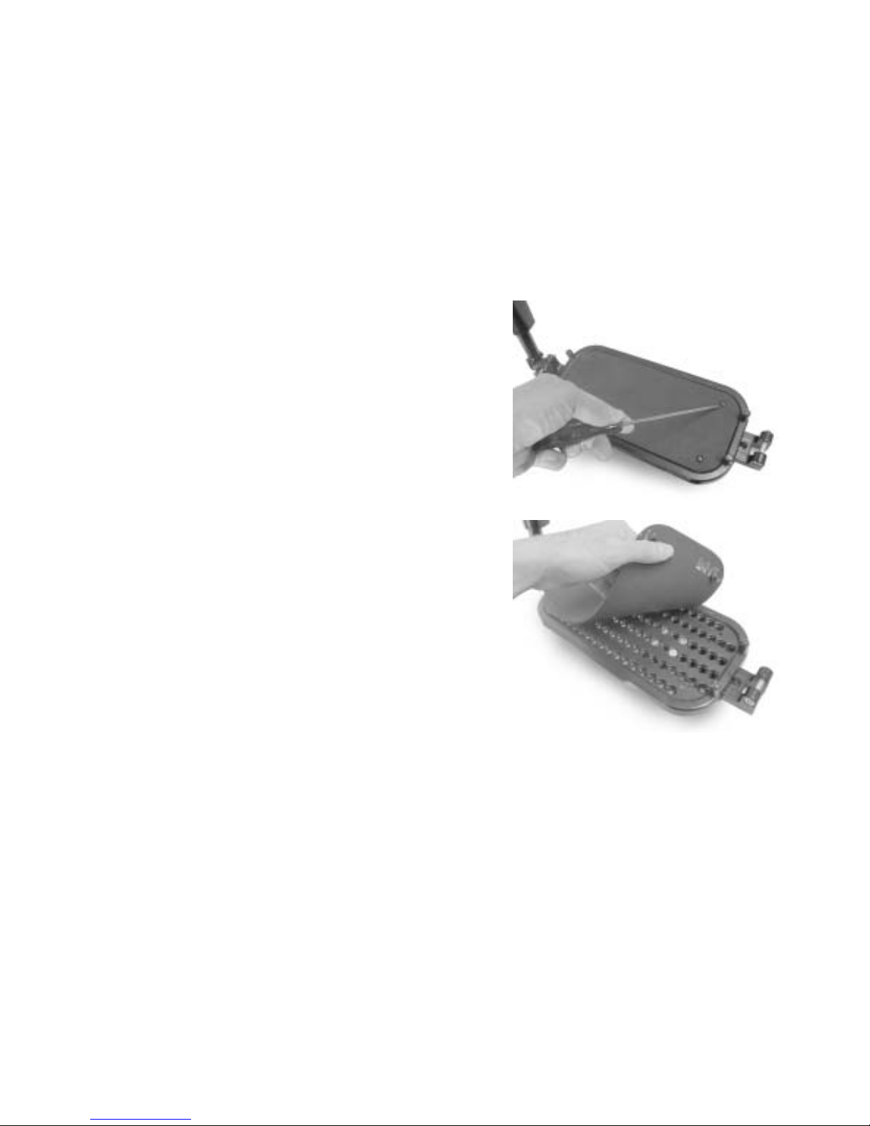
• Remove the plastic studs carefully using a flat
screwdriver.
• Remove the rubber mat.
Page 79
79
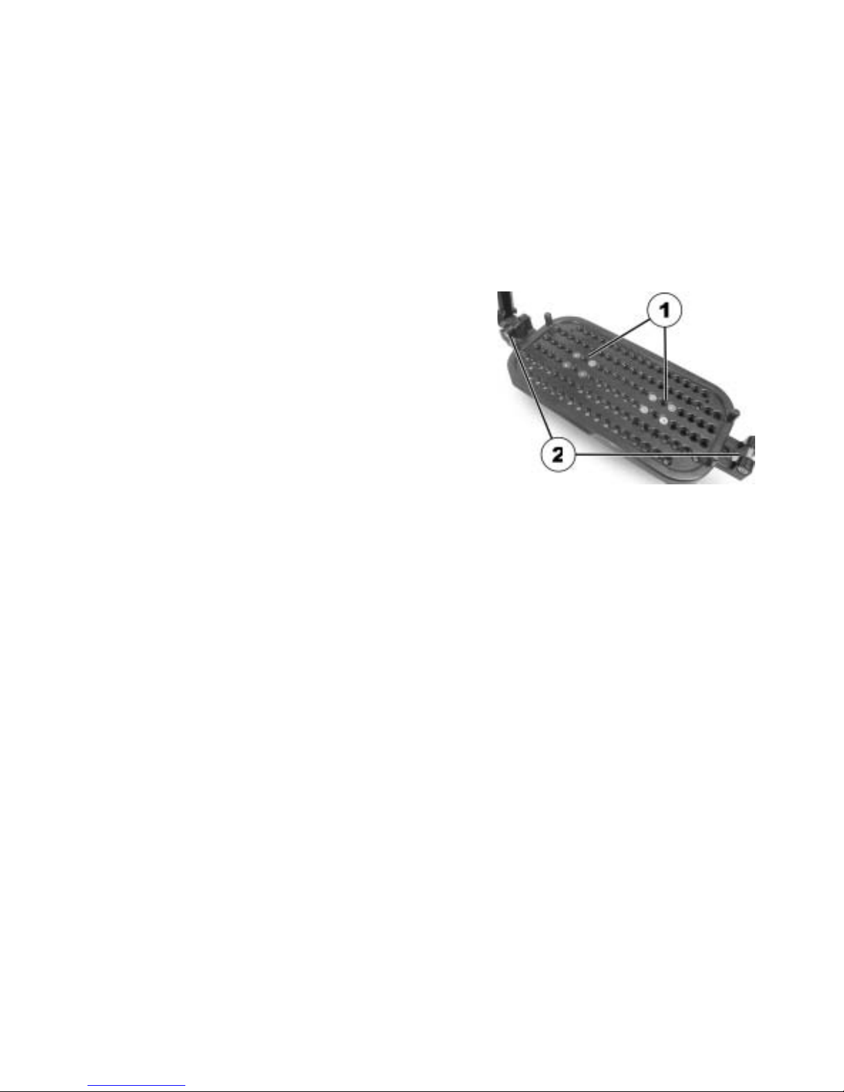
• Remove the screws (1) using the 3 mm Allen key.
• Adjust the footrest bracket (2) to the desired width.
• Re-position and tighten the screws.
Page 80

80
• If the width of the footrest has been altered, the
width of the legrest brackets (1) on the wheelchair
frame must be adapted appropriately.
• Loosen the four screws (2) using the 13 mm openended spanner.
Page 81
81
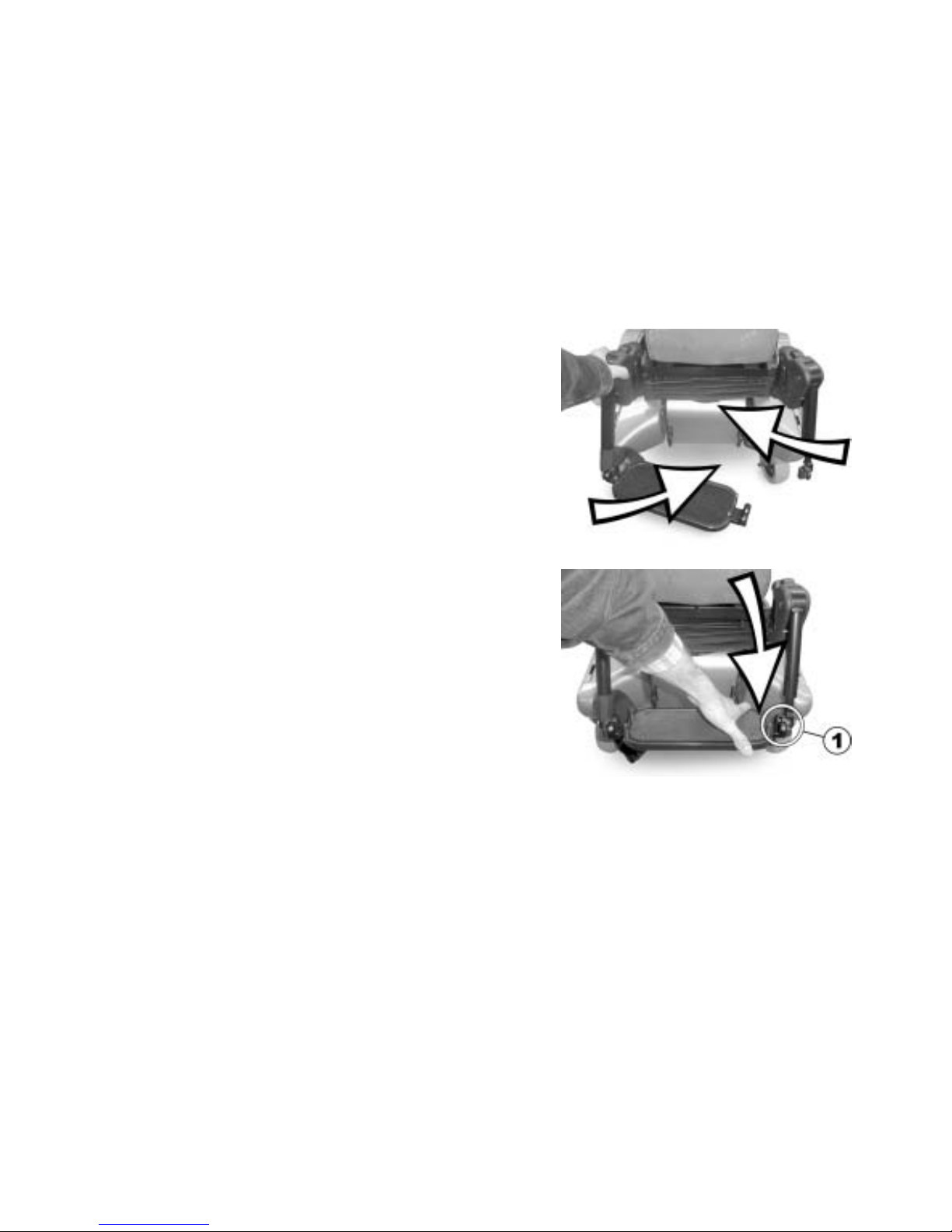
• Swivel the footrest slightly upward so that the
legrest halves can be turned inward without
colliding.
• Hang the legrest halves on the left and right and
turn inward until the locking mechanisms on both
sides lock in place.
• Swivel the footrest downward. The footrest locking
mechanism must fit exactly (1). For this adapt the
width of the legrest brackets (2).
Page 82

82
• Tighten the screw (1).
• Re-close the belt with the Velcro® fastener (2) .
Page 83

83
9.7.4.4 Adjusting the length of the legrest
Pre-requisites:
• 5 mm Allen key
• Loosen the screw (1).
• Adjust the lower leg length.
• Tighten the screw.
Page 84

84
9.7.4.5 Adjusting the angle of the legrest
Pre-requisites:
• 6 mm Allen key
• Metal pin 3 mm ∅, approx. 10 cm long
• Hammer
• Loosen the screw (1).
• Insert the metal pin into the hole (2) and knock
lightly with the hammer in order to loosen the
halves of the plastic jacket.
• Adjust the angle.
• Tighten the screw.
Page 85

85
10 Adjusting footrests and legrests
10.1 Centre-mounted legrests
10.1.1 Electric legrest
The electric legrest is operated via the remote. Please see chapter "Operating the electric
adjustment options" on page 46.
The electric legrest can be lowered completely to assist getting out of the wheelchair. To do so,
move your seat into the correct position by lowering the lifter or by means of a negative seat angle
(tilted slightly to the front).
Page 86

86
10.1.1.1 Lowering the electric legrest completely to assist getting out of the wheelchair
Warning! Misuse may destroy the legrest.
• Please read and carefully follow the instructions below.
Getting in/out of the wheelchair
• Set the lifter and tilt to a comfortable position.
• Put your feet on the footplate and pull the
lever (1). The footplates will move smoothly
down to the floor.
• Now you can get in/out of the wheelchair.
Page 87

87
Lifting up the footplates
• You are sitting in the wheelchair.
• Put your feet beside the footplates.
• Pull the lever (1). The footplates rise up
automatically.
• Let go the lever (1) and put your feet on the
footplates.
Page 88

88
Warning! Danger of damage to the legrest!
• Always make sure that the footplates are fully raised to the uppermost position before
adjusting the angle of the legrest!
• Disregarding this advice will cause damage to your legrest.
Adjusting the legrest
• Now you can adjust the angle of the legrest.
Page 89

89
10.1.2 Adjustable legrest
10.1.2.1 Adjusting the angle
Prerequisites:
• 1x 10 mm open-ended spanner
• Use the open-ended spanner to loosen the counternut
(1).
• Move the legrest to the desired position by turning the
spindle (2).
• Tighten the counternut.
Page 90
90
10.1.2.2 Adjusting the length of the legrest
Prerequisites:
• 1x 5 mm socket head spanner
• Use the socket head spanner to loosen the fastening
screws (1).
• Slide the foot support to the desired height.
• Tighten the fastening screws.
Page 91
91
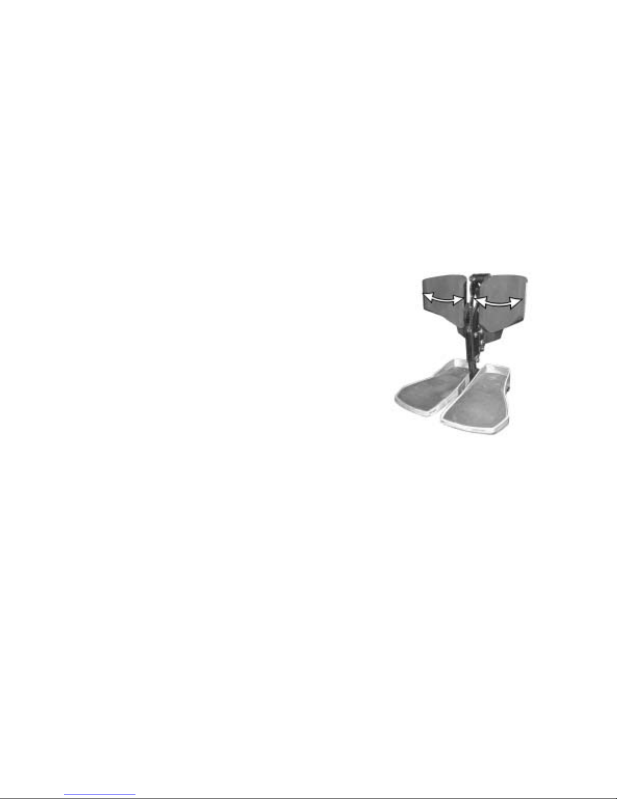
10.1.2.3 Adjusting the calf plate to the calf width of the user
The calf plate of the legrest can be adapted to the user’s calf width by bending apart or together.
• Bending the calf plate to the desired width.
Page 92

92
10.1.2.4 Adjusting the angle of the foot plate
Prerequisites:
• 1x 5 mm socket head spanner
• Fold up the foot plates in order to access the adjusting
screws.
• Use the socket head spanner to adjust the adjusting
screws (1).
• Fold the foot plate down again.
Page 93
93
10.2 Laterally mounted legrests
10.2.1 Standard footrest with pre-set angle
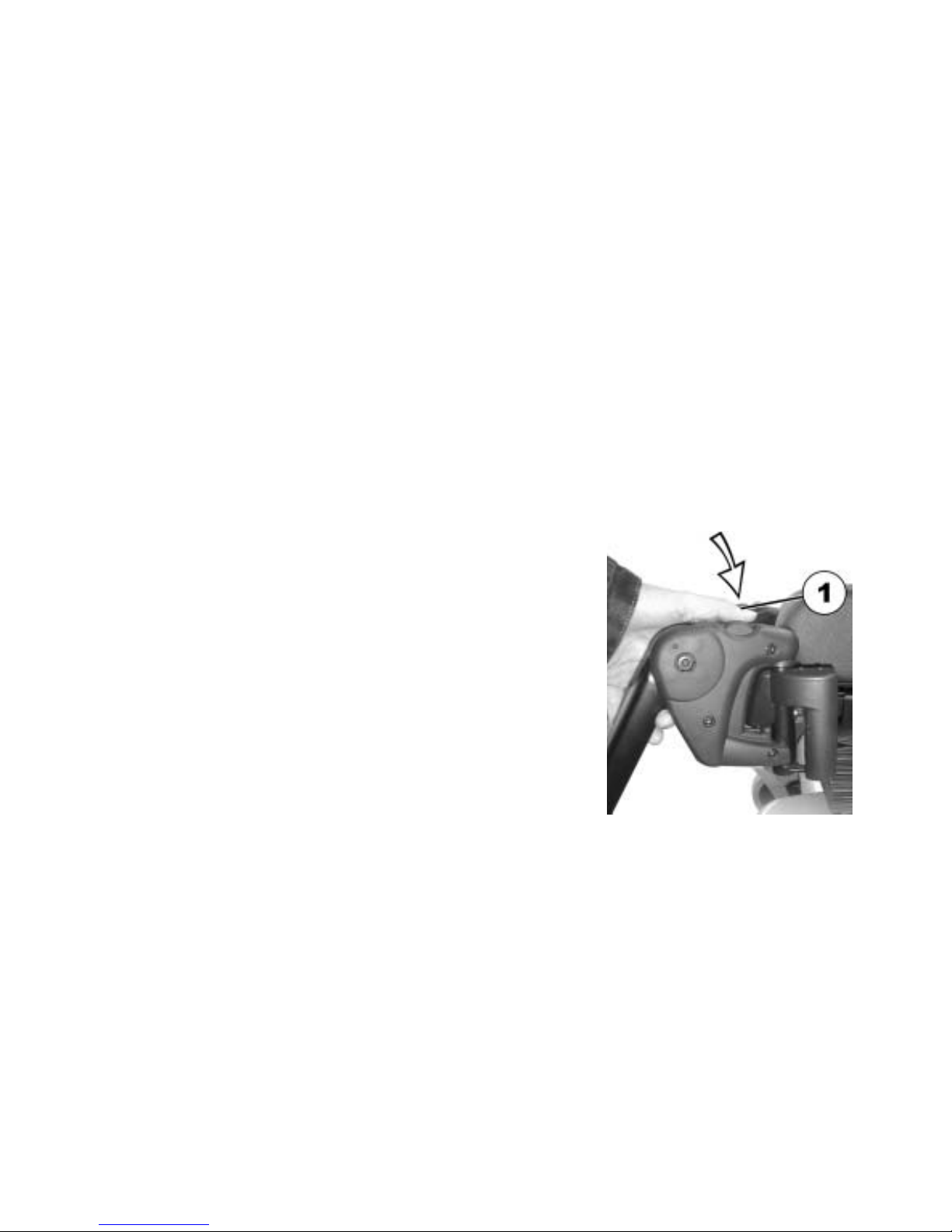
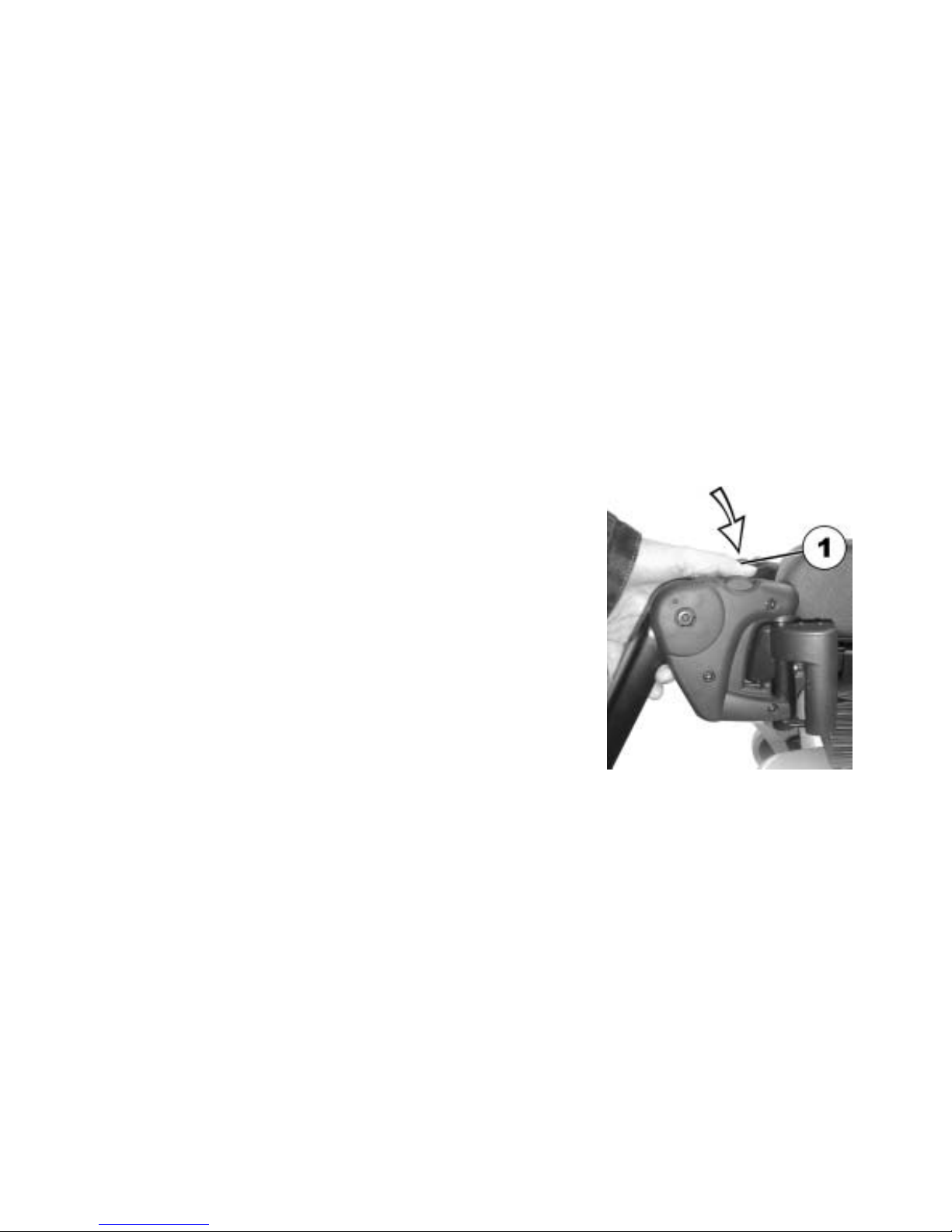
10.2.1.1 Swivelling the footrest outward and/or removing
The small unlocking button is located on the upper section of the footrest. When the footrest is
unlocked, it can be swivelled inward or outward when getting into the wheelchair as well as being
removed completely.
• Press the unlocking button (1) and swivel the footrest
outward.
• Remove the footrest in an upward direction.
Page 94
94
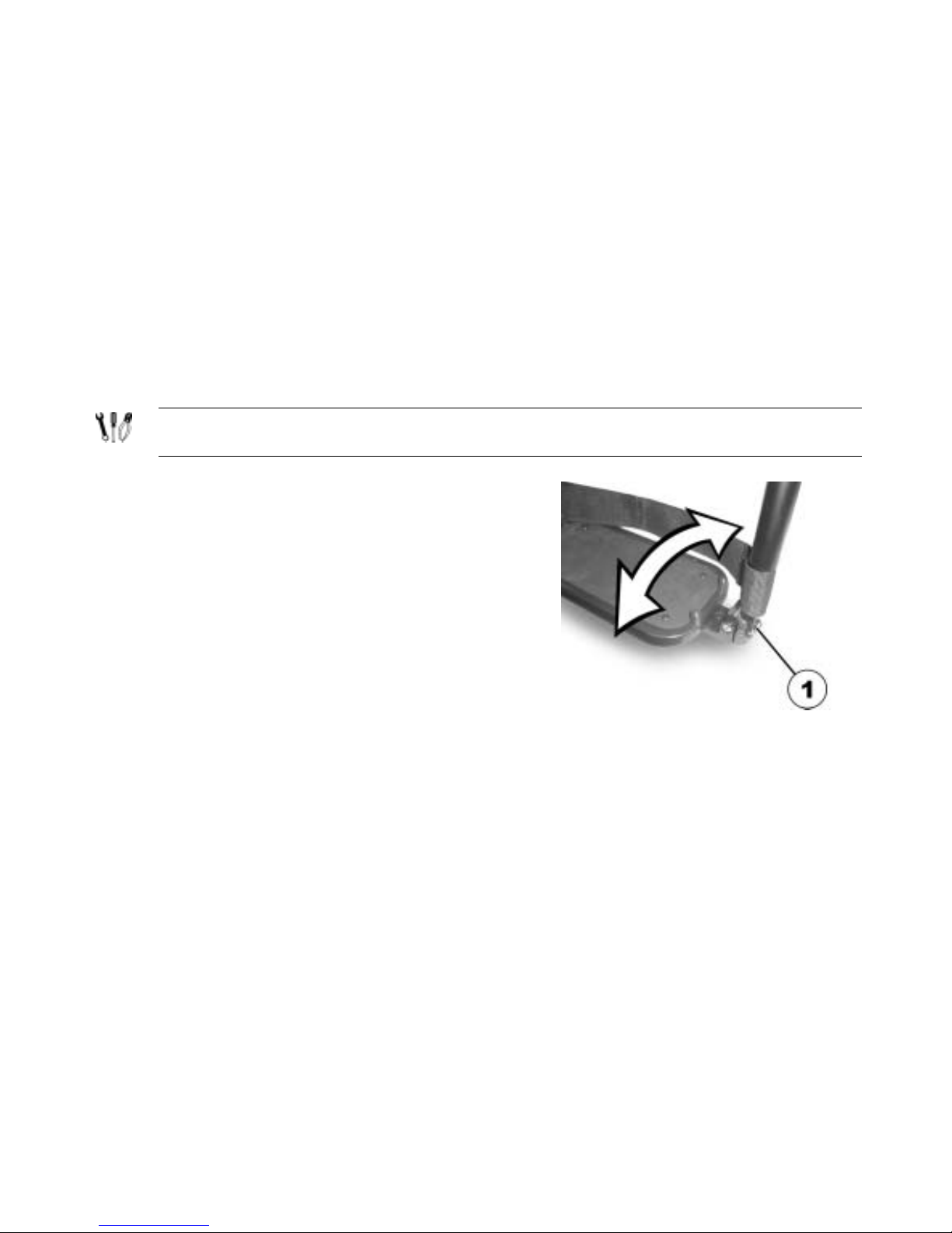
10.2.1.2 Setting the angle
PLEASE NOTE: Danger of injury due to incorrect adjustment of the footrests and legrests.
• Before and during every journey it is imperative to ensure that neither the legrests nor the
steering wheels contact the ground!
Pre-requisites:
• 1x 6 mm Allen key
• Loosen the screw (1) using the Allen key.
• If the footrest cannot be moved after loosening the screw,
position a metal pin in the designated borehole (2) and use
a hammer to knock on this lightly. The clamping mechanism
in the interior of the footrest will be released by this. Repeat
the procedure from the other side of the footrest if
necessary.
Page 95
95
• Loosen the screw (1) using the Allen key.
• Set the desired angle.
• Re-tighten the screw.
Page 96

96
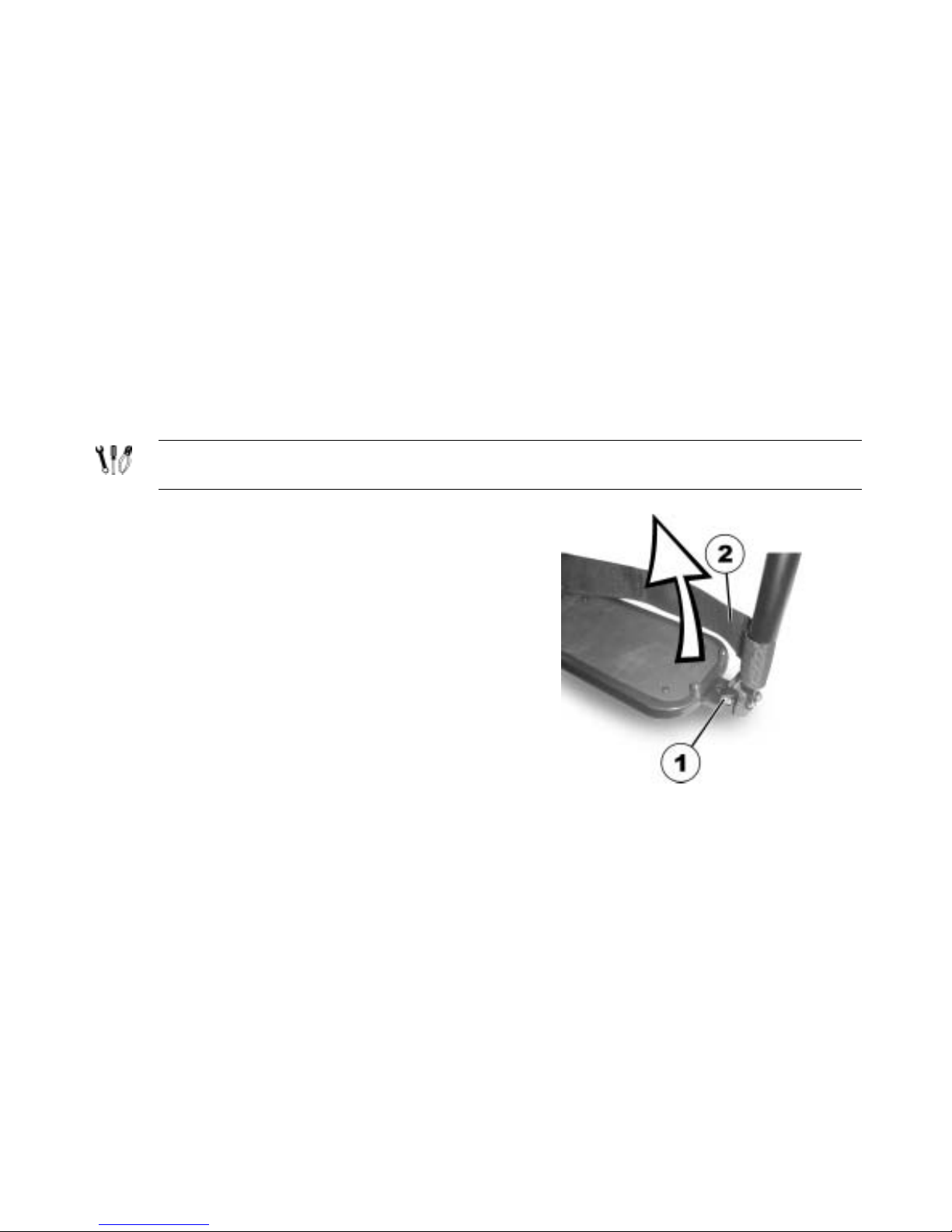
10.2.1.3 Setting the end stop of the footrest
Pre-requisites:
• 1x 6 mm Allen key
• 1x 10 mm open-ended spanner
The end position of the footrest is determined by means of a
rubber stop (1).
The rubber stop can be screwed in or out (A) or pushed up or
down (B).
Page 97

97
• Use the Allen key to loosen the screw (1) and swivel the
footrest upward in order to access the rubber stop.
• Use the open-ended spanner to loosen the counternut (1).
Page 98

98
• Move the rubber stop to the desired position
• Re-tighten the counternut
• Move the footrest to the desired position.
• Re-tighten the screw.
Page 99

99
10.2.1.4 Adjusting the length of the footrest
PLEASE NOTE: Danger of injury due to incorrect adjustment of the footrests and legrests.
• Before and during every journey it is imperative to ensure that neither the legrests nor the
steering wheels contact the ground!
Pre-requisites:
• 1x 5 mm Allen key
• Use the spanner to loosen the screw (1).
• Adjust to the desired length.
• Re-tighten the screw.
Page 100
100
10.2.2 Manually height adjustable legrest 90° - 0°
10.2.2.1 Swivelling the legrest outward and/or removing
The small unlocking button is located on the upper section of the legrest. When the legrest is
unlocked, it can be swivelled inward or outward when getting into wheelchair as well as being
removed completely.
• Press the unlocking button (1) and swivel the legrest
outward.
• Remove the legrest in an upward direction.
 Loading...