

Owner’s Operator and Maintenance Manual
P9000™ XDT
DEALER: This manual MUST be given to
the user of the wheelchair.
USER:
this manual and save for future reference.
BEFORE using this wheelchair, read
For more information regarding
Invacare products, parts, and services,
please visit www.invacare.com

WARNING
A QUALIFIED TECHNICIAN MUST PERFORM THE INITIAL SET UP
OF THIS WHEELCHAIR. ALSO, A QUALIFIED TECHNICIAN MUST
PERFORM ALL PROCEDURES IN THE SERVICE MANUAL.
WHEELCHAIR USERS: DO NOT SERVICE OR OPERATE THIS
EQUIPMENT WITHOUT FIRST READING AND UNDERSTANDING
(1) THE OWNER’S OPERATOR AND MAINTENANCE MANUAL
AND (2) THE SEATING SYSTEM’S MANUAL (IF APPLICABLE). IF
YOU ARE UNABLE TO UNDERSTAND THE WARNINGS,
CAUTIONS, AND INSTRUCTIONS, CONTACT INVACARE
TECHNICAL SUPPORT BEFORE ATTEMPTING TO SERVICE OR
OPERATE THIS EQUIPMENT - OTHERWISE INJURY OR DAMAGE
MAY RESULT.
DEALERS AND QUALIFIED TECHNICIANS: DO NOT SERVICE OR
OPERATE THIS EQUIPMENT WITHOUT FIRST READING AND
UNDERSTANDING (1) THE OWNER’S OPERATOR AND
MAINTENANCE MANUAL, (2) THE SERVICE MANUAL (IF
APPLICABLE) AND (3) THE SEATING SYSTEM’S MANUAL (IF
APPLICABLE). IF YOU ARE UNABLE TO UNDERSTAND THE
WARNINGS, CAUTIONS AND INSTRUCTIONS, CONTACT
INVACARE TECHNICAL SUPPORT BEFORE ATTEMPTING TO
SERVICE OR OPERATE THIS EQUIPMENT - OTHERWISE, INJURY
OR DAMAGE MAY RESULT.
NOTE: Updated versions of this manual are available on www.invacare.com.
P9000™ XDT 2 Part No. 1118386

TABLE OF CONTENTS
TABLE OF CONTENTS
REGISTER YOUR PRODUCT ............................................................... 6
SPECIAL NOTES ................................................................................ 9
TYPICAL PRODUCT PARAMETERS .................................................. 10
LABEL LOCATIONS ......................................................................... 11
SECTION 1—GENERAL GUIDELINES ................................................. 12
Controller Settings/Repair or Service .................................................................................................12
Operating Information.............................................................................................................................12
Tire Pressure.............................................................................................................................................14
Electrical Accessories..............................................................................................................................14
Batteries......................................................................................................................................................14
Charging Batteries ...............................................................................................................................15
Grounding Instructions ...........................................................................................................................15
Rain Test.....................................................................................................................................................16
Weight Training ........................................................................................................................................16
Weight Limitation.....................................................................................................................................16
SECTION 2—EMI INFORMATION ..................................................... 17
SECTION 3—SAFETY/HANDLING OF WHEELCHAIRS ......................... 19
Stability and Balance.................................................................................................................................19
Coping With Everyday Obstacles.........................................................................................................19
A Note to Wheelchair Assistants ........................................................................................................20
Tipping.........................................................................................................................................................20
Tipping - Curbs.....................................................................................................................................20
Lifting/Stairways ........................................................................................................................................21
Transferring to and From Other Seats ...............................................................................................22
Percentage of Weight Distribution ......................................................................................................23
Reaching, Leaning and Bending - Forward..........................................................................................23
Reaching and Bending - Backward........................................................................................................24
SECTION 4—SAFETY INSPECTION/TROUBLESHOOTING .................... 25
Safety Inspection Checklists...................................................................................................................25
Inspect/Adjust Initially.........................................................................................................................25
Inspect/Adjust Weekly........................................................................................................................26
Inspect/Adjust Monthly.......................................................................................................................26
Inspect/Adjust Periodically.................................................................................................................26
Troubleshooting - Mechanical ...............................................................................................................27
Troubleshooting Guide...........................................................................................................................27
Checking Battery Charge Level.............................................................................................................28
Part No. 1118386 3 P9000™ XDT

SECTION 5—WHEELCHAIR OPERATION ........................................... 29
SPJ™Joystick Switches and Indicators.................................................................................................29
Multi Function Charger Port.............................................................................................................29
On/Off Toggle Switch .........................................................................................................................29
Speed Control switch .........................................................................................................................29
Joystick....................................................................................................................................................29
Information Gauge Display ................................................................................................................30
Operating the Wheelchair......................................................................................................................32
Turning the Power On/Off................................................................................................................32
Using the Horn.....................................................................................................................................32
Using the Joystick to Drive the Chair.............................................................................................32
SECTION 6—FRONT RIGGINGS ........................................................ 34
Installing/Removing/Using the Footrest/Legrest................................................................................34
Installing..................................................................................................................................................34
Removing ...............................................................................................................................................35
Using .......................................................................................................................................................35
Adjusting the Footrest Height...............................................................................................................35
Replacing the Heel Loop.........................................................................................................................36
Raising/Lowering the Legrest Assembly..............................................................................................36
SECTION 7—ARMS ......................................................................... 38
Adjusting Armrest Height.......................................................................................................................38
Swing-Back Arms......................................................................................................................................39
Replacing Armrest Pad............................................................................................................................39
SECTION 8—SEAT AND BACK ......................................................... 40
Replacing the Seat Upholstery...............................................................................................................40
Replacing the Back Upholstery..............................................................................................................41
Adjusting the Back Height ......................................................................................................................42
Replacing Seat Positioning Strap ...........................................................................................................43
SECTION 9—JOYSTICK .................................................................... 44
Preparing the Joystick for Use...............................................................................................................44
Repositioning the Joystick.......................................................................................................................45
SECTION 10—CASTER .................................................................... 46
Adjusting Forks .........................................................................................................................................46
P9000™ XDT 4 Part No. 1118386

SECTION 11—BATTERIES ................................................................ 47
When to Charge Batteries.....................................................................................................................47
Charging Batteries....................................................................................................................................48
Description and Use of Battery Chargers......................................................................................48
Connecting the Battery Charger......................................................................................................49
Replacing the Batteries............................................................................................................................49
Recommended Battery Types...........................................................................................................49
Cleaning Battery Terminals ...............................................................................................................50
Removing/Installing the Battery Boxes ................................................................................................50
Installing/Removing Battery Tray......................................................................................................51
Installing/Removing Batteries Into/From Battery Boxes.............................................................52
Connecting Battery Cables ....................................................................................................................53
Direct Mount Method.........................................................................................................................54
Battery Clamp Method .......................................................................................................................57
Replacing Battery Box Retaining Strap............................................................................................60
SECTION 12—CLUTCH/MOTOR LOCK ............................................... 61
Engaging/Disengaging the Clutches.......................................................................................................61
SECTION 13—WHEEL LOCKS ............................................................ 62
Installing/Adjusting/Using the Wheel Locks .......................................................................................62
Installing/Adjusting ...............................................................................................................................62
Using .......................................................................................................................................................63
SECTION 14—ANTI-TIPPERS ........................................................... 64
Installing/Removing/Adjusting Anti-Tippers........................................................................................64
Installing..................................................................................................................................................64
Removing ...............................................................................................................................................64
Adjusting Height...................................................................................................................................64
TRANSPORTING ............................................................................ 66
Transporting the P9000 XDT................................................................................................................66
Unfolding/Folding the Wheelchair ...................................................................................................66
Unfolding ..........................................................................................................................................66
Folding ...............................................................................................................................................66
LIMITED WARRANTY ..................................................................... 68
Part No. 1118386 5 P9000™ XDT

REGISTER YOUR PRODUCT
REGISTER YOUR PRODUCT
The benefits of registering:
1. Safeguard your investment.
2. Ensure long term maintenance and servicing of your purchase.
3. Receive updates with product information, maintenance tips, and industry news.
4. Invacare can contact you or your provider, if servicing is needed on your product.
5. It will enable Invacare to improve product designs based on your input and needs.
Register ONLINE at www.invacare.com
- or -
Complete and mail the form on the next page
Any registration information you submit will be used by Invacare Corporation only, and
protected as required by applicable laws and regulations.
P9000™ XDT 6 Part No. 1118386

PRODUCT REGISTRATION FORM
Register ONLINE at www.invacare.com - or -
Complete and mail this form
Name _______________________________________________________________
Address _____________________________________________________________
City ___________________State/Province __________
Zip/Postal Code ________
Email ___________________________________Phone No. _________________
Invacare Model No. ______________________ Serial No. __________________
Purchased From _________________________Date of Purchase: ___________
1. Method of purchase: (check all that apply)
❏ Medicare ❏ Insurance ❏ Medicaid ❏ Other __________________________
2. This product was purchased for use by: (check one)
❏ Self ❏ Parent ❏ Spouse ❏ Other
3. Product was purchased for use at:
❏ Home ❏ Facility ❏ Other
4. I purchased an Invacare product because:
Cut Along Line
❏ Price ❏ Features (list features) _________________________________________
5. Who referred you to Invacare products? (check all that apply)
❏ Doctor ❏ Therapist ❏ Friend ❏ Relative ❏ Dealer/Provider ❏ Other_________
❏ Advertisement (circle one): TV, Radio, Magazine, Newspaper ❏ No Referral_____
6. What additional features, if any, would you like to see on this product?
7. Would you like information sent to you about Invacare products that may be available for a
__________________________________________________________________________
particular medical condition? ❏ Yes ❏ No
If yes, please list any condition(s) here and we will send you information by email and/or mail about
any available Invacare products that may help treat, care for or manage such condition(s):
__________________________________________________________________________
Fold
here
Fold
here
8. Would you like to receive updated information via email or regular mail about the Invacare
home medical products sold by Invacare's dealers? ❏ Yes ❏ No
9. What would you like to see on the Invacare website?
__________________________________________________________________________
10. Would you like to be part of future online surveys for Invacare products? ❏ Yes ❏ No
11. User's Year of birth: ______________________________________________________
If at any time you wish not to receive future mailings from us, please contact us at Invacare Corporation,
CRM Department, 39400 Taylor Parkway, Elyria, OH 44035, or fax to 877-619-7996 and we will remove
you from our mailing list.
To find more information about our products, visit www.invacare.com.
Fold
here
Fold
here
Cut Along Line
Invacare Product Registration Form
Please Seal with
Tape Before Mailing

SPECIAL NOTES
SPECIAL NOTES
WARNING/CAUTION notices as used in this manual apply to hazards or unsafe
practices which could result in personal injury or property damage.
NOTICE
THE INFORMATION CONTAINED IN THIS DOCUMENT IS SUBJECT TO
CHANGE WITHOUT NOTICE.
WHEELCHAIR USER
As a manufacturer of wheelchairs, Invacare endeavors to supply a wide variety of
wheelchairs to meet many needs of the end user. However, final selection of the
type of wheelchair to be used by an individual rests solely with the user and his/her
healthcare professional capable of making such a selection.
WHEELCHAIR TIE-DOWN RESTRAINTS AND SEAT RESTRAINTS
Wheelchair users should NOT be transported in vehicles of any kind while in
wheelchairs. As of this date, the Department of Transportation has not approved
any tie-down systems for transportation of a user while in a wheelchair, in a moving
vehicle of any type.
It is Invacare’s position that users of wheelchairs should be transferred into
appropriate seating in vehicles for transportation and use be made of the restraints
made available by the auto industry. Invacare cannot and does not recommend any
wheelchair transportation systems.
As regards to restraints - seat positioning straps - it is the obligation of the DME
dealer, therapists and other healthcare professionals to determine if a seating
positioning strap is required to ensure the safe operation of this equipment by the
user. Serious injury can occur in the event of a fall from a wheelchair.
WARNING
Invacare products are specifically designed and manufactured for use in conjunction
with Invacare accessories. Accessories designed by other manufacturers have not
been tested by Invacare and are not recommended for use with Invacare products.
The seat positioning strap is a positioning belt only. It is not designed for use as a
safety device withstanding high stress loads such as auto or aircraft safety belts. If
signs of wear appear, belt MUST be replaced immediately.
Part No. 1118386 9 P9000™ XDT

TYPICAL PRODUCT PARAMETERS
TYPICAL PRODUCT PARAMETERS
P9000 XDT
SEAT WIDTH 18 inches
SEAT DEPTH 16 or 18-inches (by extension)
BACK HEIGHT 17, 18, or 19 inches
SEAT-TO-FLOOR 19½ inches
OVERALL WIDTH
(EXCLUDING JOYSTICK)
OVERALL HEIGHT 38 inches (with 17 inch back)
OVERALL LENGTH 28 inches (base only) to 47 inches (with riggings and anti-tippers)
WEIGHT
W/O BATTERIES AND FRONT RIGGINGS
WITH UI BATTERIES
SHIPPING
DRIVE WHEELS/TIRES (FLAT FREE) 12½ inches x 2¼ inches
CASTERS W/PRECISION SEALED
BEARINGS 8 x 1¾ inches semi-pneumatic
Unfolded - 24½ inches
Folded - 13 inches
82 lbs
142 lbs
100 lbs
ANTI-TIPPERS Removable
FOOTRESTS/
LEGRESTS Swingaway, Removable
ARMRESTS Adjustable Height - Desk
UPHOLSTERY Black Nylon
BATTERIES
BATTERY/SIZE (NOT SUPPLIED)
TWO (2) REQUIRED U1
SPEED (M.P.H.) 0 to 4
TURNING RADIUS
CHAIR ONLY
CHAIR WITH FOOTREST
CHAIR WITH ANTI-TIPPERS
*RANGE (VARIABLE) 12-14 miles with U1 batteries
**WEIGHT LIMITATION 250 lbs
Front - 26 inches; Rear - 13 inches
36 inches
16 inches
*NOTE: Range will vary with battery conditions, surface, terrain and operating weight.
**NOTE: Includes seating system and accessories.
P9000™ XDT 10 Part No. 1118386
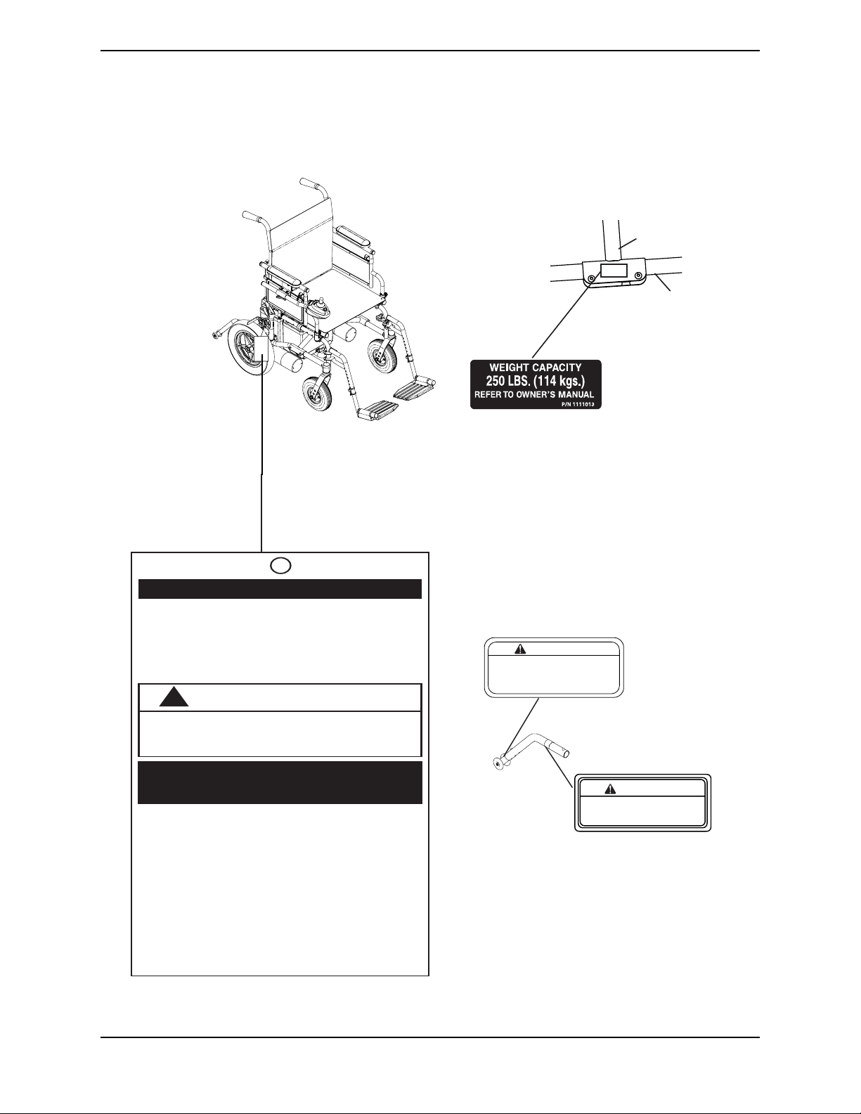
LABEL LOCATIONS
LABEL LOCATIONS
Crossmember
Lower Frame
Tube
IMPORTANT NOTICE
T he wheel locks on this wheelchair have been
pre-set at the factory to comply with the
V eterans Administration functional S tandard
8320.01 of the Federal Register , paragraph
3.2.4.5.3. If these wheel locks do not meet
your needs, follow instructions below .
!
CAUTION
Any w heel lock adjustments should embed
wheel lock shoe at least 1/8" into tire when
locked (3/16" on pneumatic tires).
INSTRUCTIONS FOR WHEEL
LOCK ADJUSTMENTS
1. Loosen wheel lock mounting fastener ,
which runs through mounting bracket and
frame.
2. Slide clamp toward rear wheel until wheel
lock shoe is embedded into tire material at
least 1/8" when handle is engaged to the
lock position (3/16" for pneumatic tires).
3. Tighten mounting fastener to secure
mounting bracket in desired location and
recheck lock sh oe embedding.
4. Inspect for correct locking action BEFORE
actual use.
00078X021-0394
WARNING
Refer to Owner's Manual
for proper anti-tipper
setting.
1085379
REV. 5/98
WARNING
DO NOT OPERATE WITHOUT
THE ANTI-TIP TUBES
INSTALLED.
P/N 60106X144
Part No. 1118386 11 P9000™ XDT

SECTION 1—GENERAL GUIDELINES
SECTION 1—GENERAL GUIDELINES
WARNING
This section contains important information for the safe operation and use of this
product. DO NOT use this product or any available optional equipment without
first completely reading and understanding these instructions and any additional
instructional material such as Owner’s Manuals, Service Manuals or Instruction
Sheets supplied with this product or optional equipment. If you are unable to understand the Warnings, Cautions or Instructions, contact a healthcare professional,
dealer or technical personnel before attempting to use this equipment - otherwise,
injury or damage may occur.
Controller Settings/Repair or Service
CAUTION
Set-up of the Electronic Control Unit is to be performed only by a qualified technician. The fine tuning adjustments of the controller may affect other activities of the
wheelchair. Reprogramming the controller reduces the stability/control of the
wheelchair. Other program settings could cause the wheelchair to tip over resulting
in serious injury to the user and/or damage to the surrounding property. If any individual other than a qualified technician performs any work on these units, the warranty is void.
Operating Information
Performance adjustments should only be made by professionals of the healthcare field or
persons fully conversant with this process and the driver's capabilities. Incorrect settings
could cause injury to the driver, bystanders, damage to the chair and to surrounding
property.
After the wheelchair has been set-up, check to make sure that the wheelchair performs to
the specifications entered during the set-up procedure. If the wheelchair does not
perform to specifications, turn the wheelchair off immediately and reenter set-up
specifications. Repeat this procedure until the wheelchair performs to specifications.
ALWAYS shift your weight in the direction you are turning. DO NOT shift your weight in
the opposite direction of the turn. Shifting your weight in the opposite direction of the
turn may cause the inside drive wheel to lose traction and the wheelchair to tip over.
DO NOT shift your weight or sitting position toward the direction you are reaching as the
wheelchair may tip over.
DO determine and establish your particular safety limits by practicing bending, reaching
and transferring activities in the presence of a qualified healthcare professional before
attempting active use of the wheelchair.
P9000™ XDT 12 Part No. 1118386

SECTION 1—GENERAL GUIDELINES
DO NOT attempt to reach objects if you have to move forward in the seat.
DO NOT attempt to reach objects if you have to pick them up from the floor by reaching
down between your knees.
DO NOT lean over the top of the back upholstery to reach objects from behind as this may
cause the wheelchair to tip over.
DO NOT use an escalator to move a wheelchair between floors. Serious bodily injury may
occur.
Before attempting to transfer in or out of the wheelchair, every precaution should be
taken to reduce the gap distance. Turn both casters parallel to the object you are
transferring onto. Also, be certain the power is off and the wheel locks are engaged to
prevent the wheels from moving.
DO NOT engage or disengage the motor release levers until the power is in the off
position.
Invacare strongly recommends proceeding down ramps or slopes at half speed or slower
and to avoid hard braking or sudden stops.
DO NOT attempt to lift the wheelchair by lifting on any removable (detachable) parts.
Lifting by means of any removable (detachable) parts of a wheelchair may result in injury
to the user or damage to the wheelchair.
Anti-tippers MUST be used at all times. When outdoors on wet, soft ground or gravel
surfaces, anti-tippers may not provide the same level of protection against tipover. Extra
caution must be observed when traversing such surfaces.
Wheel locks are not brakes. DO NOT attempt to stop a moving wheelchair with the wheel
locks.
DO NOT engage or disengage the clutches until the power is in the OFF position.
DO NOT operate on roads, streets or highways.
DO NOT climb, go up or down ramps or traverse slopes greater than 9°.
DO NOT attempt to move up or down an incline with a water, ice or oil film.
DO NOT attempt to drive over curbs or obstacles. Doing so may cause your wheelchair
to turn over and cause bodily harm or damage to the chair.
DO NOT leave the power button in the on position when entering or exiting your
wheelchair.
DO NOT stand on the frame of the wheelchair.
DO NOT use the footplates as a platform. When getting in or out of the wheelchair, make
sure that the footplates are in the upward position or swing the footrests toward the
outside of the chair.
DO NOT stand on the front riggings, otherwise damage may occur. When getting in or
out of the wheelchair, make sure that the footplates on the front riggings are in the
upward position or moved out of the way.
ALWAYS wear your seat positioning strap.
Part No. 1118386 13 P9000™ XDT

SECTION 1—GENERAL GUIDELINES
The seat positioning strap is a positioning belt only. It is not designed for use as a safety
device withstanding high stress loads such as auto or aircraft safety belts. If signs of wear
appear, belt must be replaced immediately.
Always verify that hand grips on the rear cane are secure prior to use when an assistant
is used to propel or lift the chair. Check for any signs of looseness or deterioration and if
found, contact a qualified technician. Do not attempt to move the wheelchair by using the
hand grips if they are found to be unsecure or have deteriorated.
When cleaning rear cane or hand grip areas use only a clean towel lightly dampened with
cool water. Verify that grips are dry prior to use. Use of soap or ammonia based cleaning
solutions will result in the hand grips sliding off the cane assembly. Failure to observe this
warning may result in injury to the user or bystanders.
DO NOT sit or transfer into the wheelchair unless it is fully open and the seat frame rails
are fully seated into the side frame H-blocks.
Before performing any maintenance, adjustment or service verify that On/Off switch on
the joystick is in the Off position.
Avoid storage or use near external flame or combustible products.
Tire Pressure
DO NOT use your wheelchair unless it has the proper tire pressure (P.S.I.).
DO NOT overinflate the tires. Failure to follow these suggestions can cause the tire to
explode and cause bodily harm. The recommended tire pressure is listed on the side wall
of the tire.
Electrical Accessories
EXTREME care should be exercised when using oxygen in close proximity to electric
circuits and other combustible materials. Contact your oxygen supplier for instruction in
the use of oxygen.
Batteries
The warranty and performance specifications contained in this manual are based on the
use of deep cycle gel cell or sealed lead acid batteries. Invacare strongly recommends their
use as the power source for this unit.
If wet cell batteries are used, follow all manufacturer guidelines and instructions for
installation and maintenance. Regardless of battery type, proper battery footprint and use
of battery terminal caps as defined in Batteries on page 47 must be followed.
Carefully read battery/battery charger information prior to installing, servicing or
operating your wheelchair.
P9000™ XDT 14 Part No. 1118386

SECTION 1—GENERAL GUIDELINES
Charging Batteries
NEVER attempt to recharge the batteries by attaching cables directly to the battery
terminals.
DO NOT attempt to recharge the batteries and operate the wheelchair at the same time.
DO NOT operate wheelchair with extension cord attached to the AC cable.
DO NOT attempt to recharge the batteries when the wheelchair has been exposed to ANY
type of moisture.
DO NOT attempt to recharge the batteries when the wheelchair is outside.
DO NOT sit in the wheelchair while charging the batteries.
DO NOT attempt to recharge batteries using at the same time BOTH the on-board battery
charger AND an independent battery charger plugged into the joystick charger port.
Doing so will reduce the life of the batteries.
READ and carefully follow the manufacturer’s instructions for each charger (supplied or
purchased). If charging instructions are not supplied, consult a qualified technician for
proper procedures.
After charging batteries, ALWAYS make sure that the battery charger cord is unplugged.
Failure to do this could result in damage to the cord or personal injury to the user or
bystanders.
When using an extension cord, use only a three (3) wire extension cord having at least 16
AWG (American Wire Gauge) wire and the same or higher electrical rating as the device
being connected.
Use of improper extension cord could result in risk of fire and electric shock.
Ensure the pins of the extension cord plug are the same number, size, and shape as those
on the charger.
DO NOT under any circumstances cut or remove the round grounding plug from the
charger AC cable plug or the extension cord plug.
Three (3) prong to two (2) prong adapters should not be used. Use of three (3) prong
adapters can result in improper grounding and present a shock hazard to the user.
Grounding Instructions
DO NOT, under any circumstances, cut or remove the round grounding prong from any
plug used with or for Invacare products. Some devices are equipped with three-prong
(grounding) plugs for protection against possible shock hazards and fire. Where a
two-prong wall receptacle is encountered, it is the personal responsibility and obligation
of the customer to contact a qualified electrician and have the two-prong receptacle
replaced with a properly grounded three-prong wall receptacle in accordance with the
National Electrical Code. If you must use an extension cord, use ONLY a three-wire
extension cord having the same or higher electrical rating as the device being connected.
In addition, Invacare has placed RED/ORANGE warning tags on some equipment. DO
NOT remove these tags.
Part No. 1118386 15 P9000™ XDT

SECTION 1—GENERAL GUIDELINES
Rain Test
Invacare has tested its power wheelchairs in accordance with ISO 7176 “Rain Test.” This
provides the end user or his/her assistant sufficient time to remove his/her power
wheelchair from a rain storm and retain wheelchair operation.
DO NOT leave power wheelchair in a rain storm of any kind.
DO NOT use power wheelchair in a shower or leave it in a damp bathroom while taking
a shower.
DO NOT store power wheelchair in a damp area for an extended period of time.
Direct exposure to excessive rain or dampness may cause the chair to malfunction
electrically and mechanically, may cause the chair to prematurely rust or may damage the
upholstery.
Check to ensure that the RED and GREY battery terminal caps are secured in place,
joystick boot is NOT torn or cracked where water can enter and that all electrical
connections are secure at all times.
DO NOT use the wheelchair if the joystick boot is torn or cracked. If the joystick boot
becomes torn or cracked, replace IMMEDIATELY.
Weight Training
Invacare DOES NOT recommend the use of its wheelchairs as a weight training
apparatus. Invacare wheelchairs have not been designed or tested as a seat for any kind
of weight training. If occupant uses said wheelchair as a weight training apparatus,
Invacare shall NOT be liable for bodily injury and the warranty is void.
Weight Limitation
The P9000 XDT has a weight limitation, including seating system and accessories, of 250
lbs. Refer to Percentage of Weight Distribution
only heavy-duty wheelchairs should be used for individuals weighing more than 250 lbs.
Further, the activity level of the individual wheelchair user is important. For instance, a
170 lb. active wheelchair could subject the wheelchair to more stress than a 250 lb. user.
Invacare recommends that very active users consider the use of heavy-duty wheelchairs.
on page 23. Invacare recommends that
P9000™ XDT 16 Part No. 1118386

SECTION 2—EMI INFORMATION
SECTION 2—EMI INFORMATION
WARNING
CAUTION: IT IS VERY IMPORTANT THAT YOU READ THIS INFORMATION
REGARDING THE POSSIBLE EFFECTS OF ELECTROMAGNETIC
INTERFERENCE ON YOUR POWERED WHEELCHAIR.
Electromagnetic Interference (EMI) From Radio Wave Sources
Powered wheelchairs and motorized scooters (in this text, both will be referred to
as powered wheelchairs) may be susceptible to electromagnetic interference (EMI),
which is interfering electromagnetic energy (EM) emitted from sources such as
radio stations, TV stations, amateur radio (HAM) transmitters, two way radios, and
cellular phones. The interference (from radio wave sources) can cause the powered
wheelchair to release its brakes, move by itself, or move in unintended directions. It
can also permanently damage the powered wheelchair's control system. The
intensity of the interfering EM energy can be measured in volts per meter (V/m).
Each powered wheelchair can resist EMI up to a certain intensity. This is called its
"immunity level." The higher the immunity level, the greater the protection. At this
time, current technology is capable of achieving at least a 20 V/m immunity level,
which would provide useful protection from the more common sources of radiated
EMI.
There are a number of sources of relatively intense electromagnetic fields in the
everyday environment. Some of these sources are obvious and easy to avoid.
Others are not apparent and exposure is unavoidable. However, we believe that by
following the warnings listed below, your risk to EMI will be minimized.
The sources of radiated EMI can be broadly classified into three types:
1) Hand-held Portable transceivers (transmitters-receivers with the antenna
mounted directly on the transmitting unit. Examples include: citizens band (CB)
radios, "walkie talkie", security, fire and police transceivers, cellular telephones,
and other personal communication devices).
NOTE: Some cellular telephones and similar devices transmit signals while they are ON,
even when not being used.
2) Medium-range mobile transceivers, such as those used in police cars, fire trucks,
ambulances and taxis. These usually have the antenna mounted on the outside of
the vehicle; and
3) Long-range transmitters and transceivers, such as commercial broadcast
transmitters (radio and TV broadcast antenna towers) and amateur (HAM)
radios.
NOTE: Other types of hand-held devices, such as cordless phones, laptop computers,
AM/FM radios, TV sets, CD players, cassette players, and small appliances, such as
electric shavers and hair dryers, so far as we know, are not likely to cause EMI problems
to your powered wheelchair.
Part No. 1118386 17 P9000™ XDT

SECTION 2—EMI INFORMATION
WARNING
Powered Wheelchair Electromagnetic Interference (EMI)
Because EM energy rapidly becomes more intense as one moves closer to the
transmitting antenna (source), the EM fields from hand-held radio wave sources
(transceivers) are of special concern. It is possible to unintentionally bring high
levels of EM energy very close to the powered wheelchair's control system while
using these devices. This can affect powered wheelchair movement and braking.
Therefore, the warnings listed below are recommended to prevent possible
interference with the control system of the powered wheelchair.
Electromagnetic interference (EMI) from sources such as radio and TV stations,
amateur radio (HAM) transmitters, two-way radios, and cellular phones can affect
powered wheelchairs and motorized scooters.
FOLLOWING THE WARNINGS LISTED BELOW SHOULD REDUCE THE
CHANCE OF UNINTENDED BRAKE RELEASE OR POWERED WHEELCHAIR
MOVEMENT WHICH COULD RESULT IN SERIOUS INJURY.
1) Do not operate hand-held transceivers (transmitters receivers), such as citizens
band (CB) radios, or turn ON personal communication devices, such as cellular
phones, while the powered wheelchair is turned ON;
2) Be aware of nearby transmitters, such as radio or TV stations, and try to avoid
coming close to them;
3) If unintended movement or brake release occurs, turn the powered wheelchair
OFF as soon as it is safe;
4) Be aware that adding accessories or components, or modifying the powered
wheelchair, may make it more susceptible to EMI.
NOTE: There is no easy way to evaluate their effect on the overall immunity of the
powered wheelchair).
5) Report all incidents of unintended movement or brake release to the powered
wheelchair manufacturer, and note whether there is a source of EMI nearby.
Important Information
1) 20 volts per meter (V/m) is a generally achievable and useful immunity level
against EMI (as of May 1994) (the higher the level, the greater the protection);
2) The immunity level of the product is unknown.
Modification of any kind to the electronics of this wheelchair as manufactured by
Invacare may adversely affect the RFI immunity levels.
P9000™ XDT 18 Part No. 1118386

SECTION 3—SAFETY/HANDLING OF WHEELCHAIRS
SECTION 3—SAFETY/HANDLING OF
WHEELCHAIRS
“Safety and Handling” of the wheelchair requires the close attention of the wheelchair
user as well as the assistant. This manual points out the most common procedures and
techniques involved in the safe operation and maintenance of the wheelchair. It is
important to practice and master these safe techniques until you are comfortable in
maneuvering around the frequently encountered architectural barriers.
Use this information only as a “basic” guide. The techniques that are discussed on the
following pages have been used successfully by many.
Individual wheelchair users often develop skills to deal with daily living activities that
may differ from those described in this manual. Invacare recognizes and encourages each
individual to try what works best for him/her in overcoming architectural obstacles that
they may encounter. However, all warnings and cautions given in this manual MUST be
followed. Techniques in this manual are a starting point for the new wheelchair user and
assistant with “safety” as the most important consideration for all.
Stability and Balance
WARNING
ALWAYS wear your seat positioning strap.
The seat positioning strap is a positioning belt only. It is not designed for use as a
safety device withstanding high stress loads such as auto or aircraft safety belts. If
signs of wear appear, belt MUST be replaced immediately.
To assure stability and proper operation of your wheelchair, you must at all times
maintain proper balance. Your wheelchair has been designed to remain upright and
stable during normal daily activities as long as you do not move beyond the center of
gravity. DO NOT lean forward out of the wheelchair any further than the length of the
armrests.
Coping With Everyday Obstacles
Coping with the irritation of everyday obstacles can be alleviated somewhat by learning
how to manage your wheelchair. Keep in mind your center of gravity to maintain stability
and balance.
While the walking beam allows you to traverse up to a 2-inch bump or threshold,
stopping after the wheels cross the bump poses a problem. The chair cannot reverse over
the bump at this point. Continue forward and then turn around.
Part No. 1118386 19 P9000™ XDT

SECTION 3—SAFETY/HANDLING OF WHEELCHAIRS
While the P9000 XDT is designed for use primarily in and around the home, the provider
should determine whether this chair is suitable for the actual environment the chair will
be used in.
DO NOT go down ramp at full speed. Some seat/back positions will cause wheelchair to
feel unstable.
CAUTION
Be aware of condition of ramp. Traction will be diminished/nonexistent on a slippery surface. Proceed with caution.
A Note to Wheelchair Assistants
When assistance to the wheelchair user is required, remember to use good body
mechanics. Keep your back straight and bend your knees whenever tilting wheelchair or
traversing curbs or other impediments.
Also, be aware of detachable parts such as arms or legrests. These must NEVER be used
to move the wheelchair or as lifting supports, as they may be inadvertently released,
resulting in possible injury to the user and/or assistant(s).
When learning a new assistance technique, have an experienced assistant help you before
attempting it alone.
Tipping
WARNING
DO NOT tip the wheelchair without assistance.
When tipping the wheelchair, an assistant should grasp the back of the wheelchair on a
non-removable (non-detachable) part. Inform the wheelchair occupant before tipping the
wheelchair and remind him/her to lean back. Be sure the occupant’s feet and hands are
clear of all wheels.
Tipping - Curbs
After mastering the techniques of tipping the wheelchair, use this procedure to tackle
curbs, short stairs, etc.
This procedure requires two (2) assistants. The second assistant should be positioned at
the front of the wheelchair lifting upward on a non-removable (non-detachable) part of
the wheelchair frame when lifting the wheelchair and stabilizing the wheelchair when the
wheelchair is being lowered to the ground.
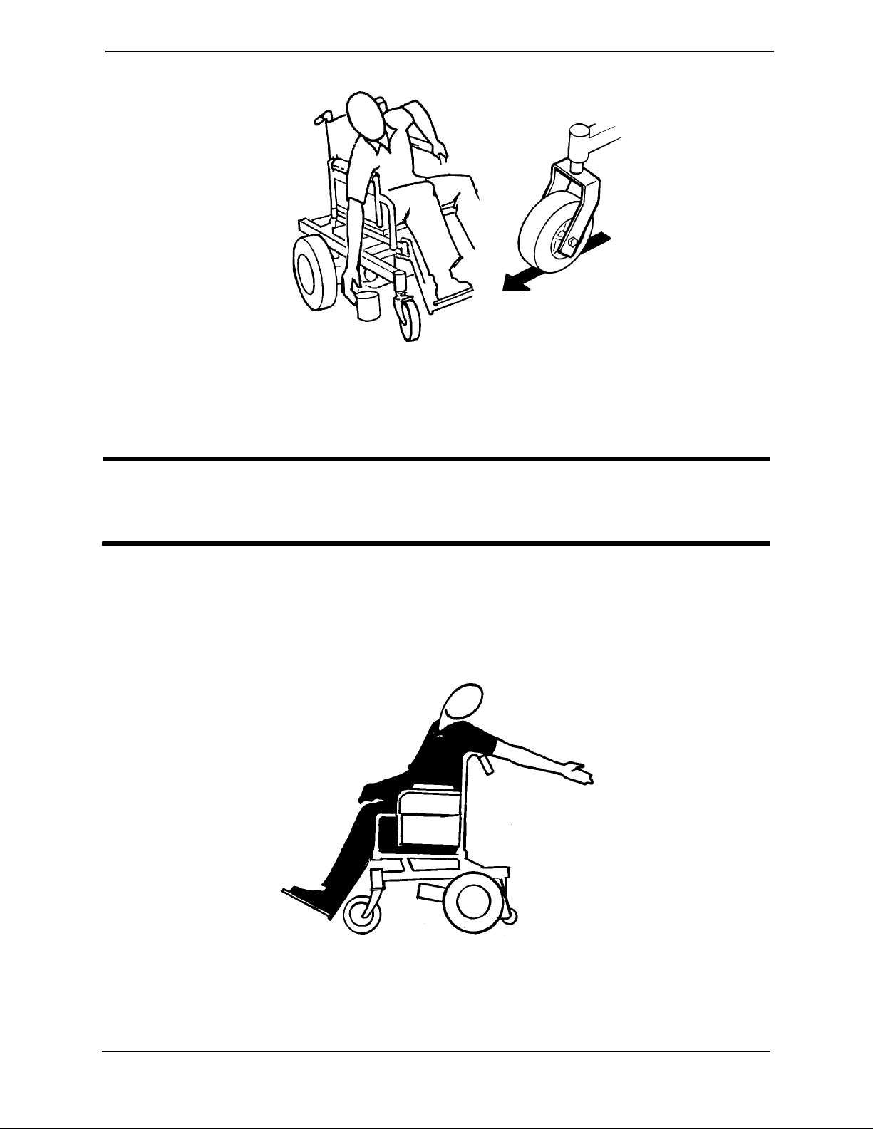
The first assistant should turn the anti-tippers so the wheels are pointing up, apply a
continuous downward motion until the balance point is achieved and the front casters
clear the curb. At this point, the assistants will feel a difference in the weight distribution.
P9000™ XDT 20 Part No. 1118386

SECTION 3—SAFETY/HANDLING OF WHEELCHAIRS
WARNING
DO NOT let the wheelchair drop the last few inches to the ground. This could result
in injury to the occupant.
Roll the wheelchair forward and SLOWLY lower the wheelchair in one continuous
movement. Push the wheelchair forward until the rear wheels roll up and over the curb.
WARNING
Make sure anti-tipper wheels are pointing down towards the ground/floor before
using the wheelchair.
Turn the anti-tipper wheels down towards the ground/floor.
Lifting/Stairways
WARNING
DO NOT attempt to move an occupied power wheelchair between floors using a
stairway. Use an elevator to move an occupied power wheelchair between floors. If
moving a power wheelchair between floors by means of a stairway, the occupant
MUST be removed and transported independently of the power wheelchair.
Extreme caution is advised when it is necessary to move an unoccupied power
wheelchair up or down the stairs. Invacare recommends using two (2) assistants and
making thorough preparations.
Use ONLY secure, nondetachable parts for hand-hold supports.
It is strongly recommended to lift the wheelchair only by the rear frame and the
front forks - otherwise injury or damage may occur.
DO NOT attempt to lift the wheelchair by any removable (detachable) parts.
Lifting by means of any removable (detachable) parts of a wheelchair may result in
injury to the user or damage to the wheelchair.
The weight of the wheelchair without the user and batteries is between 80 and 127
lbs.
Follow this procedure for moving the wheelchair between floors when an elevator is NOT
available or lifting the wheelchair is necessary:
NOTE: When using a stairway to move the wheelchair, seat and any accessories, move all
wheelchair components away from the stairway prior to reassembly.
1. Remove the occupant from the wheelchair.
2. Remove the battery boxes from the wheelchair. Refer to Removing/Installing the
Battery Boxes on page 50.
3. If necessary, fold the wheelchair. Refer to Transporting the P9000 XDT on page 66.
4. Bend your knees and keep your back straight.
Part No. 1118386 21 P9000™ XDT
SECTION 3—SAFETY/HANDLING OF WHEELCHAIRS
5. Using non-removable (non-detachable) parts of the wheelchair, lift the wheelchair off
the ground and transfer the wheelchair up or down the stairs.
6. The wheelchair should not be lowered until the last stair has been negotiated and the
wheelchair has been carried away from the stairway.
ESCALATORS WARNING
DO NOT use an escalator to move a wheelchair between floors. Serious bodily
injury may occur.
Transferring to and From Other Seats
WARNING
ALWAYS turn the wheelchair power OFF and engage the clutches to prevent the
wheels from moving BEFORE attempting to transfer in or out of the wheelchair.
Also make sure every precaution is taken to reduce the gap distance by turning
both casters parallel to the object you are transferring onto.
CAUTION
When transferring, position yourself as far back as possible in the seat. This will prevent broken screws, damaged upholstery and the possibility of the wheelchair tipping forward.
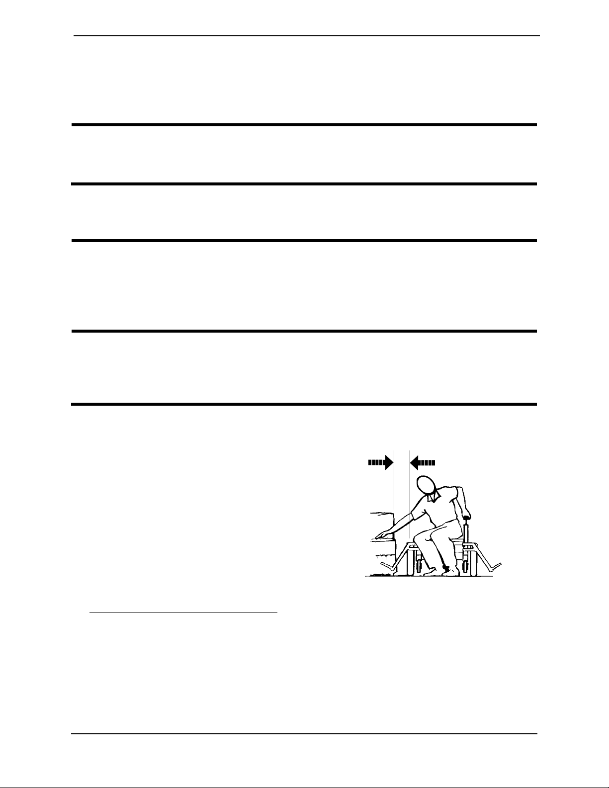
NOTE: This activity may be performed
independently provided you have adequate
mobility and upper body strength.
NOTE: For this procedure, refer to
FIGURE 3.1.
1. Position the wheelchair as close as
possible along side the seat to which
you are transferring, with the casters
pointing parallel to it.
2. After the wheelchair is positioned
properly for transfer, verify that the
clutches are engaged. Refer to
Engaging/Disengaging the Clutches
page 61.
on
Minimum Gap Distance
FIGURE 3.1 Transferring to and From
Other Seats
3. Shift body weight into seat with transfer.
During independent transfer, little or no seat platform will be beneath you. Use a transfer
board if at all possible.
P9000™ XDT 22 Part No. 1118386

SECTION 3—SAFETY/HANDLING OF WHEELCHAIRS
Percentage of Weight Distribution
WARNING
DO NOT attempt to reach objects if you have to move forward in the seat or pick
them up from the floor by reaching down between your knees.
Proper positioning is essential for your safety. When reaching, leaning, bending or
bending forward, it is important to use the casters as a tool to maintain stability and
balance.
Many activities require the wheelchair user to reach, bend and transfer in and out of
the wheelchair. These movements will cause a change to the normal balance, center of gravity, and weight distribution of the wheelchair. To determine and establish
your particular safety limits, practice bending, reaching and transferring activities in
several combinations in the presence of a qualified healthcare professional before
attempting active use of the wheelchair.
Reaching, Leaning and Bending - Forward
NOTE: For this procedure, refer to FIGURE 3.2.
1. Position the front casters as far forward as possible.
2. Engage clutches and, if applicable, wheel locks*.
WARNING
DO NOT attempt to reach objects if you have to move forward in the seat or pick
them up from the floor by reaching down between your knees.
*Wheel locks are an option. You can order the wheelchair with or without wheel
locks. Transfer to and from the wheelchair in the presence of a qualified healthcare
professional to determine individual safety limits. Invacare strongly recommends
ordering the wheel locks as an additional safeguard for the wheelchair user.
Part No. 1118386 23 P9000™ XDT
SECTION 3—SAFETY/HANDLING OF WHEELCHAIRS
FIGURE 3.2 Reaching, Leaning and Bending - Forward
Reaching and Bending - Backward
WARNING
DO NOT lean over the top of the back upholstery. This will change your center of
gravity and may cause you to tip over.
NOTE: For this procedure, refer to FIGURE 3.3.
1. Position wheelchair as close as possible to the desired object.
2. Point the front and rear casters rearward to create the longest possible wheelbase.
3. Reach back only as far as your arm will extend without changing your sitting position.
FIGURE 3.3 Reaching and Bending - Backward
P9000™ XDT 24 Part No. 1118386

SECTION 4—SAFETY INSPECTION/TROUBLESHOOTING
SECTION 4—SAFETY
INSPECTION/TROUBLESHOOTING
NOTE: Every six (6) months or as necessary take your wheelchair to a qualified dealer for a
thorough inspection and servicing. Regular cleaning will reveal loose or worn parts and enhance
the smooth operation of your wheelchair. To operate properly and safely, your wheelchair must be
cared for just like any other vehicle. Routine maintenance will extend the life and efficiency of your
wheelchair.
Safety Inspection Checklists
CAUTION
As with any vehicle, wheels and tires should be checked periodically for cracks and
wear and should be replaced as necessary.
Initial adjustments should be made to suit your personal body structure needs and
preference. Thereafter follow these maintenance procedures:
Inspect/Adjust Initially
❑ Ensure that the wheelchair rolls straight (no excessive drag or pull to one side).
❑ Ensure that all fasteners on the clothing guards are secure.
❑ Ensure that the arms are secure but easy to release and adjustment levers engage
properly.
❑ Ensure that adjustable height arms operate and lock securely.
❑ Ensure armrest pads sit flush against arm tubes.
❑ Ensure seat is secured to wheelchair frame.
❑ Clean seat upholstery and armrests.
❑ Ensure wheel mounting nuts are secure on drive wheels.
❑ Ensure no excessive side movement or binding occurs when drive wheels are lifted
and spun when disengaged (free-wheeling).
❑ Ensure that drive wheel axle bolts and locking tab washers are secure.
❑ Ensure that the wheel locks engage properly and do not interfere with the tires when
rolling. Also, ensure that the pivot points are free of wear and looseness.
❑ Inspect caster assembly has proper tension when caster is spun. Caster should come
to a gradual stop.
❑ Loosen/tighten caster locknut if wheel wobbles noticeably or binds to a stop.
❑ Ensure all caster/wheel/fork/headtube fasteners are secure.
❑ Inspect tires for flat spots and wear. If tires are pneumatic, check for proper inflation.
Part No. 1118386 25 P9000™ XDT

SECTION 4—SAFETY INSPECTION/TROUBLESHOOTING
❑ Seat and/or back upholstery have no rips and do not sag. Replace if necessary.
Inspect/Adjust Weekly
❑ Seat is secured to wheelchair frame.
❑ Seat release latch is not worn and is functional. Replace if necessary.
❑ Inspect tires for flat spots and wear. If the tires are pneumatic, check for proper
inflation.
❑ Ensure all caster/wheel/fork/headtube fasteners are secure.
❑ Ensure arm pivot points are not worn and/or loose. Replace if necessary.
Inspect/Adjust Monthly
❑ Ensure wheel mounting nuts are secure on drive wheels.
❑ Ensure no excessive side movement or binding occurs when drive wheels are lifted
and spun when disengaged (free-wheeling).
❑ Ensure that drive wheel axle bolts and locking tab washers are secure.
❑ Inspect caster assembly has proper tension when caster is spun. Caster should come
to a gradual stop.
❑ Loosen/tighten caster locknut if wheel wobbles noticeably or binds to a stop.
❑ Ensure that the wheel locks engage properly and do not interfere with the tires when
rolling. Also, ensure that the pivot points are free of wear and looseness.
❑ Inspect the seat positioning strap for signs of wear. Replace if worn or damaged.
❑ Ensure that the buckle on the seat positioning strap latches. Replace if necessary.
❑ Verify that the hardware that attaches the seat positioning strap to the seat frame is
secure and undamaged. Replace if necessary.
Inspect/Adjust Periodically
❑ Ensure wheelchair rolls straight (no excessive drag or pull to one side).
❑ Ensure that all fasteners on the clothing guards are secure.
❑ Ensure arms are secure but easy to release and adjustment levers engage properly.
❑ Ensure adjustable height arms operate and lock securely.
❑ Ensure arm pivot points are not worn and/or loose. Replace if necessary.
❑ Ensure armrest pads sit flush against arm tubes.
❑ Ensure seat and/or back upholstery have no rips and do not sag. Replace if necessary.
❑ Ensure seat release latch is not worn. Replace if necessary.
❑ Seat and/or back upholstery have no rips and do not sag. Replace if necessary.
❑ Clean upholstery and armrests.
P9000™ XDT 26 Part No. 1118386

SECTION 4—SAFETY INSPECTION/TROUBLESHOOTING
❑ Inspect charger AC power cord for damage. Replace if necessary.
Troubleshooting - Mechanical
Chair
Veers
Left/Right
XXX X
XXXXX
XX
Sluggish
Turn/Performance
Casters
Flutter
Squeaks
and
Rattles
Looseness
In Chair
Chair 3
Wheels
Troubleshooting Guide
Solutions
If pneumatic,
check tires for
correct and
equal pressure.
Check for
loose stem
nuts/bolts.
Check that
both casters
contact ground
at the same
time.
SYMPTOM PROBABLE CAUSE SOLUTIONS
Batteries draw excessive
current when charging.
Battery indicator flashes the
charge level is low immediately after recharging.
Battery indicator flashes the
charge level is low too soon
after being recharged.
Motor chatters or runs
irregularly.
Wheelchair does not
respond to commands.
Power on, battery indicator
flashes.
Only one (1) drive wheel
turns.
Battery failure.
Electrical malfunction.
Battery failure.
Charger malfunction.
Electrical malfunction.
Batteries not charged.
Weak batteries.
Electrical malfunction.
Electrical malfunction. Contact dealer/Invacare.
One (1) or both clutches
disengaged.
Electrical malfunction.
One (1) clutch is disengaged.
Have batteries checked for shorted cell. Replace
if necessary.
Contact dealer/Invacare for service.
Check batteries for shorted cell. Replace if necessary.
Contact dealer/Invacare.
Poor connections between charger and wheelchair. Contact dealer/Invacare for service.
Have charger checked.
Replace batteries if necessary.
Contact dealer/Invacare for service.
Engage motor locks/clutches.
Contact dealer/Invacare for service.
Engage clutch.
Part No. 1118386 27 P9000™ XDT

SECTION 4—SAFETY INSPECTION/TROUBLESHOOTING
SYMPTOM PROBABLE CAUSE SOLUTIONS
Joystick erratic or does not
respond as desired.
Wheelchair does not
respond to commands.
Power indicator off - even
after recharging.
Electrical malfunction.
Controller programmed
improperly.
Poor battery terminal connection.
Electrical malfunction.
Contact dealer/Invacare for service.
Reprogram controller. Contact dealer/Invacare
for service.
Clean terminals.
Contact dealer/Invacare.
NOTE: For additional troubleshooting information and explanation of error codes, refer to the
Electronics Manual (P/N 1110532) supplied with each wheelchair.
Checking Battery Charge Level
DON’T DO
Don’t perform any installation or maintenance without first reading this manual.
Don’t make it a habit to discharge batteries to the
lowest level.
Read and understand this manual and any service information that accompanies a battery and charger before
operating the wheelchair.
Recharge as frequently as possible to maintain a high
charge level and extend battery life.
Don’t use randomly chosen batteries/chargers.
Don’t put new batteries into service before charging.
Don’t tip or tilt batteries.
Don’t tap on clamps or terminals with tools.
Don’t mismatch your battery and chargers.
Don’t use randomly chosen batteries or chargers.
Follow recommendations in this manual when selecting a
battery or charger.
Fully charge a new battery before using. Use a carrying
strap to remove, move or install a battery.
Push battery clamps onto terminals. Spread clamps wider
if necessary.
Use ONLY a GEL charger for a GEL or sealed battery
and a regular charger for regular batteries.
P9000™ XDT 28 Part No. 1118386

SECTION 5—WHEELCHAIR OPERATION
SECTION 5—WHEELCHAIR
OPERATION
WARNING
After ANY adjustments, repair or service and BEFORE use, make sure that all
attaching hardware is tightened securely - otherwise injury or damage may result.
Set-up/programming of the Electronic Control Unit is to be performed ONLY by a
qualified technician. The fine tuning adjustments of the controller may affect other
activities of the wheelchair. Damage to the equipment could occur under these circumstances. IF UNQUALIFIED INDIVIDUALS PERFORM ANY WORK ON
THESE UNITS, THE WARRANTY IS VOID.
SPJ™Joystick Switches and Indicators
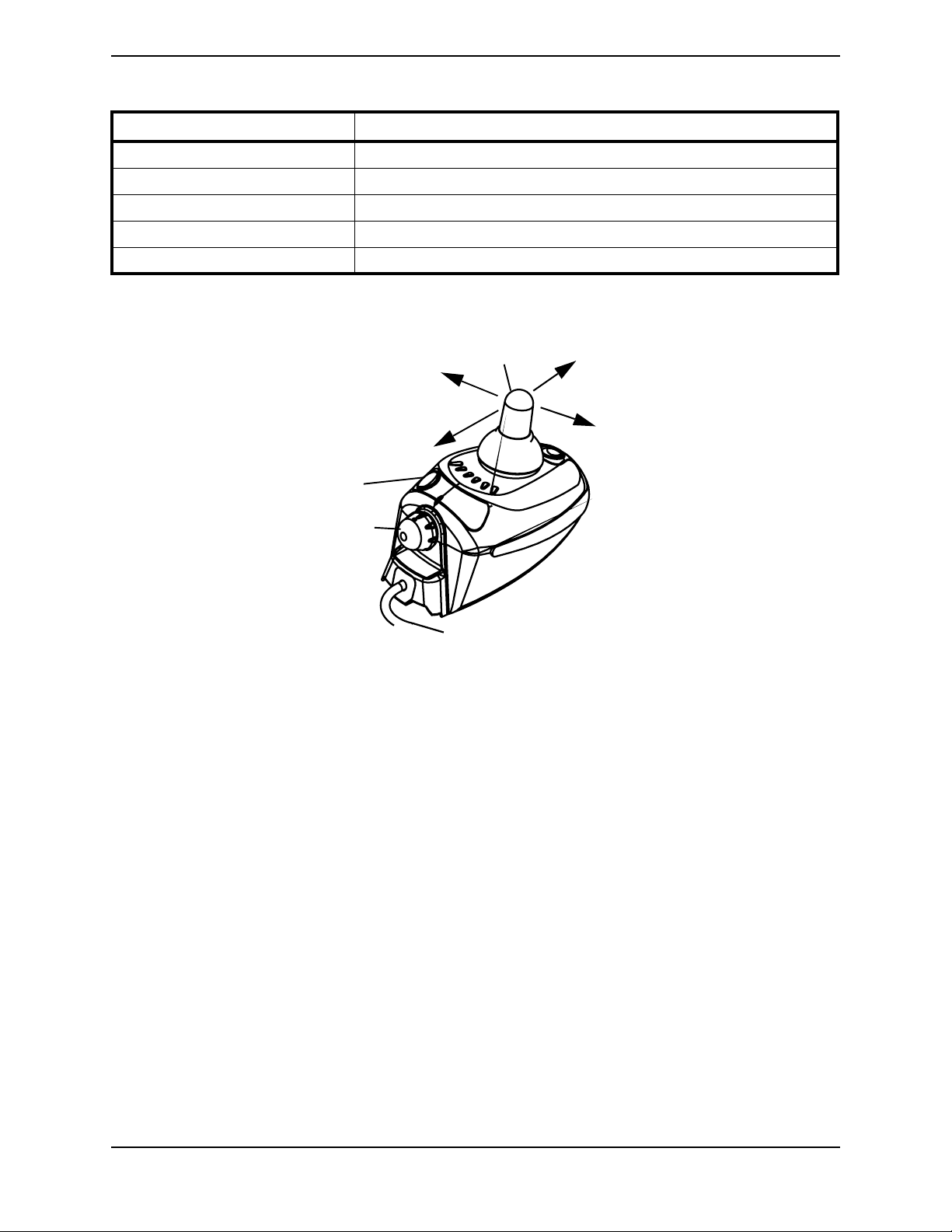
NOTE: For the following information, refer to FIGURE 5.1.
Multi Function Charger Port
The multi function charger port is located at the front of the joystick housing. This
provides easy access for charging the wheelchair batteries. This port also serves as the
Remote Programmer Communication connection.
On/Off Toggle Switch
This toggle switch is located at the back of the joystick housing.
Speed Control switch
The speed control switch is located on the back of the joystick housing. This rotary switch
is used for controlling the speed and acceleration of the wheelchair.
1. Turn the switch clockwise to increase the speed of the wheelchair.
2. Turn the switch counterclockwise to decrease the speed of the wheelchair.
Joystick
The joystick has proportional drive control, meaning that further the joystick is pushed
from the upright (neutral) position, the faster the wheelchair moves. Your top speed,
however, is limited by the setting of the speed-control knob and programmed settings.
To slow the wheelchair to a stop, simply release the joystick. The wheelchair has
automatic speed and direction compensation to minimize corrections.
Part No. 1118386 29 P9000™ XDT

SECTION 5—WHEELCHAIR OPERATION
Horn
Multi-Function
Charger Port
Information
Gauge
Joystick
On/Off
Button
Speed Control
Knob
To Controller
FIGURE 5.1 SPJ™Joystick Switches and Indicators
Information Gauge Display
The Information Gauge Display is located on the front of the joystick housing. It provides
the following information to the user on the status of the wheelchair -
1. Power is on.
2. True state-of-battery-charge, including notification of when the battery requires
charging:
A. GREEN LED is lit, indicating well charged batteries.
B. Only AMBER LEDs are lit, indicating batteries are moderately charged. Recharge
batteries before taking a long trip.
C. Only RED LED is lit, indicating batteries are running out of charge. Recharge
batteries as soon as possible.
3. Program, inhibit or charge modes.
4. Fault indication (Flash Codes).
The Information Gauge display also serves as a system diagnostic device when a fault is
detected by the control module. A specific number of flashes of the LEDs indicate the type
of fault detected. Refer to the following table of the diagnostic indications of the
wheelchair status.
P9000™ XDT 30 Part No. 1118386

SECTION 5—WHEELCHAIR OPERATION
DISPLAY DESCRIPTION DEFINITION COMMENTS
All LEDs are OFF. Power is OFF.
INVACARE
All LEDs are ON. Power is ON. Fewer than three (3)
LEDs on implies reduced
INVACARE
Left RED LED is flashing. Battery charge is low. The batteries should be
INVACARE
battery charge.
charged as soon as possible.
INVACARE
INVACARE
INVACARE
Left to Right “chase” alternating with steady display.
Right GREEN LED is flashing.
Joystick is in programming, inhibit and/or charging mode.
Joystick is in SPEED LIMIT
mode.
The steady LEDs indicate
the current state of the
battery charge.
The current state of battery charge will be displayed at the same time.
INVACARE
All LEDs are flashing slowly. Joystick has detected
Out-of-Neu-
Release the joystick back
to Neutral.
tral-at-Power-Up mode.
All LEDs are flashing
quickly.
Joystick has detected a
fault.
Joystick uses Flash codes
to indicate faults. Refer to
the electronics manual
(P/N1110532).
Part No. 1118386 31 P9000™ XDT

SECTION 5—WHEELCHAIR OPERATION
Operating the Wheelchair
NOTE: For this procedure, refer to FIGURE 5.2.
Turning the Power On/Off
1. To turn the power ON, press the on/off button.
NOTE: After turning power on, all indicators will light briefly and the display gauge will indicate
one of the following:
A. The Current Battery Charge - Shows all LEDs lit or partial LEDs lit. Refer to the
preceding information gauge display table.
B. Out Of Neutral At Power up - Shows all LEDs flashing slowly. This occurs when
the power is turned on when the joystick is out of neutral. This feature prevents
sudden and unexpected movements of the power chair.
2. To turn the power off, press the on/off button.
Using the Horn
1. Press the horn button located above the information gauge on the joystick housing.
Using the Joystick to Drive the Chair
The joystick is located at the front of the joystick housing and provides smooth control of
speed and direction. It is equipped with 360 degrees of mobility for ease of operation. The
joystick is spring-loaded, and automatically returns to the upright (neutral) position
when released. Pushing the joystick in a given direction causes the chair to move in that
direction.
The joystick has proportional drive control, meaning that the further it is pushed from the
upright (neutral) position, the faster the wheelchair moves. The maximum speed,
however, is limited by the setting of the speed-control knob.
To slow the wheelchair to a stop, simply release the joystick. The wheelchair has
automatic speed and direction compensation to minimize corrections.
When first learning to drive, select a slow speed and try to drive the wheelchair as slowly
as possible by pushing the joystick slightly forward. This exercise will help you learn to
utilize the full potential of the proportional control and allow you to start and stop
smoothly.
To drive the wheelchair, perform the following:
1. Adjust speed control switch to the appropriate setting.
2. Turn the power on. Refer to Turning the Power On/Off
P9000™ XDT 32 Part No. 1118386
on page 32.
SECTION 5—WHEELCHAIR OPERATION
3. Move the joystick in the following manner:
MOVEMENT ACTION
FORWARD Push forward on the joystick.
REVERSE Pull back on the joystick.
Turn RIGHT Move the joystick RIGHT.
Turn LEFT Move the joystick LEFT.
STOP Release the joystick and the wheelchair will quickly slow down.
NOTE: The joystick MUST be in the NEUTRAL position for an accurate reading of battery
charge.
To Move Left
Joystick
To Move Forward
To Move Backward
On/Off Button
Speed Control Knob
FIGURE 5.2 Using the Joystick to Drive the Chair
To Move Right
Part No. 1118386 33 P9000™ XDT

SECTION 6—FRONT RIGGINGS
SECTION 6—FRONT RIGGINGS
WARNING
After ANY adjustments, repair or service and BEFORE use, make sure that all
attaching hardware is tightened securely - otherwise injury or damage may result.
Before performing any maintenance, adjustment or service verify that ON/OFF
switch on the joystick is in the OFF position.
Installing/Removing/Using the Footrest/Legrest
NOTE: For this procedure, refer to FIGURE 6.1.
NOTE: This procedure applies to the swingaway footrest and elevating legrest.
Installing
1. Turn the swingaway footrest assembly to the side (open footplate is perpendicular to
wheelchair).
2. Install the hinge plates on the swingaway footrest assembly onto the hinge pins on the
wheelchair frame.
3. Push the swingaway footrest assembly towards the inside of the wheelchair until it
locks into place.
NOTE: The footplate will be on the inside of the wheelchair when locked in place.
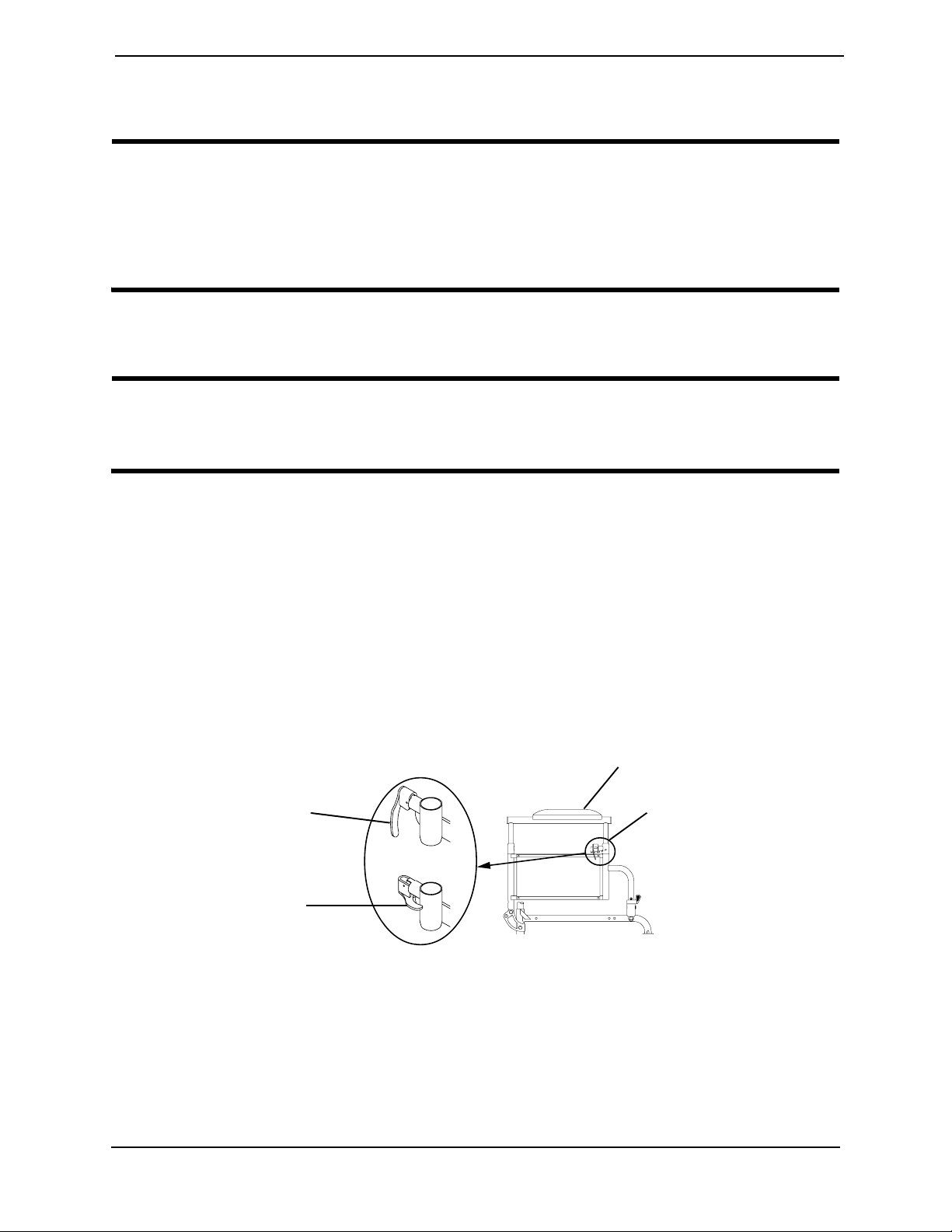
4. Repeat this procedure for the other footrest assembly.
Footrest
Release Lever
Swingaway
Footrest
Assembly
Hinge
Pins
Hinge
Plates
Footplate
FIGURE 6.1 Installing/Removing/Using the Footrest/Legrest
P9000™ XDT 34 Part No. 1118386
SECTION 6—FRONT RIGGINGS
Removing
1. Push the footrest release lever inward.
2. Rotate swingaway footrest assembly outward.
3. Lift the swingaway footrest assembly off of the hinge pins.
Using
1. To move the footrest out of the way without removing, push the footrest release lever
inward, rotate footrest outward.
2. To lock the footrest, push the swingaway footrest assembly towards the inside of the
wheelchair until it locks into place.
NOTE: The footplate will be on the inside of the wheelchair when locked in place.
Adjusting the Footrest Height
NOTE: For this procedure, refer to FIGURE 6.2.
NOTE: This procedure applies to the swingaway footrest and elevating legrest.
1. Remove the swingaway footrest assembly. Refer to Installing/Removing/Using the
Footrest/Legrest on page 34.
NOTE: Lay the assembly on a flat surface to simplify this procedure.
2. Remove impact guards and/or calf strap, if installed.
3. Pull the cam lock lever up to the unlocked position.
4. Push in the release buttons and reposition the lower footrest assembly to the desired
height.
5. Ensure that the release buttons fully protrude from holes on both sides of the upper
footrest support.
6. Rotate cam lock lever down to locked
position.
7. Replace impact guards and/or calf
Upper Footrest Support
strap.
8. Repeat this procedure for the other
footrest, if necessary.
9. Reinstall the swingaway footrest
assembly. Refer to
Adjustment
Holes
Cam Lock Lever
Release Button
Lower Footrest
Assembly
Installing/Removing/Using the
Footrest/Legrest on page 34.
FIGURE 6.2 Adjusting the Footrest Height
Part No. 1118386 35 P9000™ XDT
SECTION 6—FRONT RIGGINGS
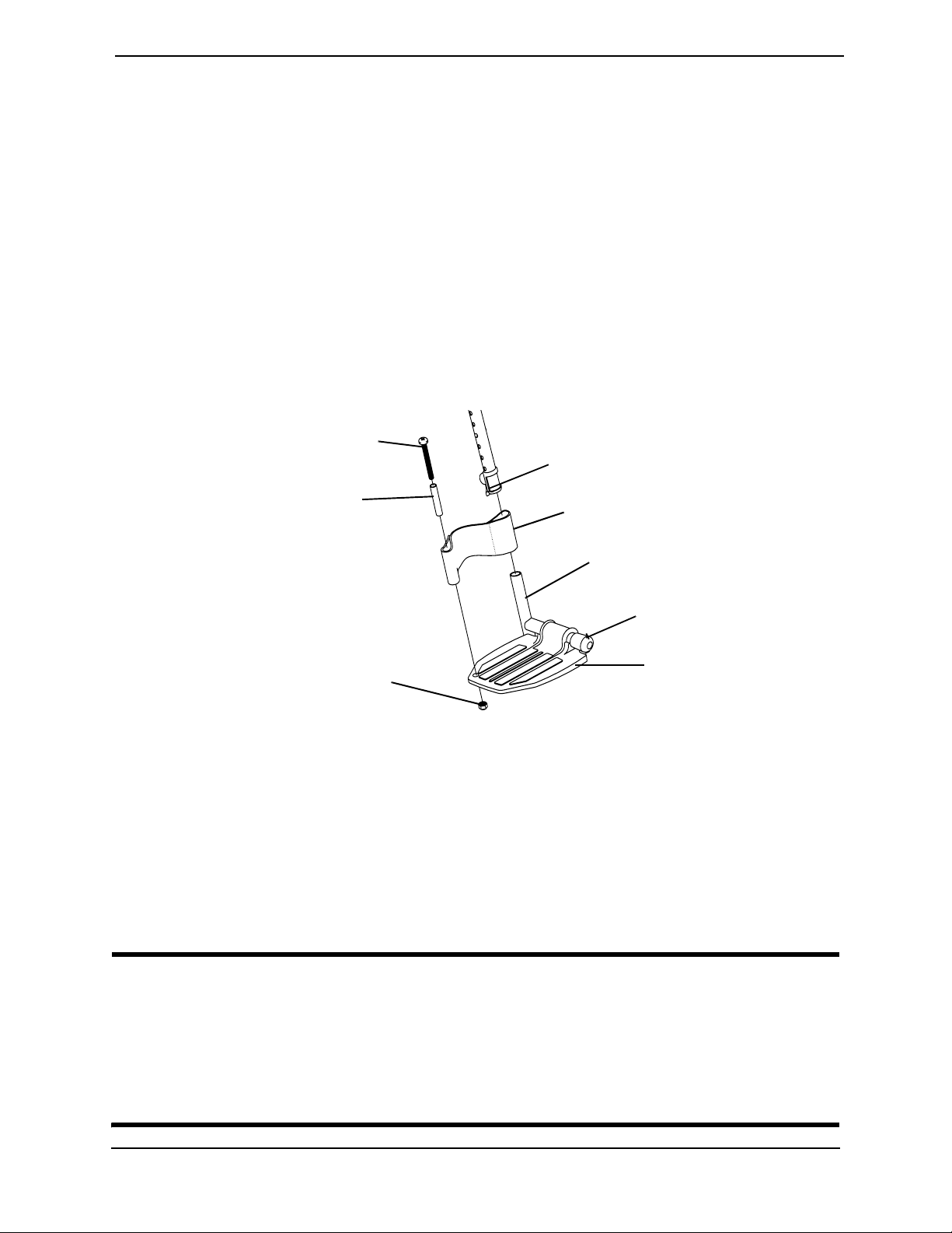
Replacing the Heel Loop
NOTE: For this procedure, refer to FIGURE 6.3.
1. Pull the cam lock lever up to the unlocked position.
2. Push in the release buttons and remove the lower footrest assembly.
3. Remove the mounting screw, spacer and locknut that secure the heel loop to the
footrest.
4. Remove existing heel loop from slide tube.
5. Install new heel loop onto slide tube.
6. Install the mounting screw, spacer and locknut to secure the heel loop to the footrest.
Tighten until the spacer is secure.
Mounting Screw
Cam Lock Lever
Spacer
Locknut
FIGURE 6.3 Replacing the Heel Loop
7. Insert the lower footrest assembly into the upper footrest assembly to desired height.
8. Ensure that the release buttons fully protrude from holes on both sides of the upper
footrest support.
9. Rotate cam lock lever down to locked position.
Heel Loop
Slide Tube
Lower Footrest
Assembly
Footrest
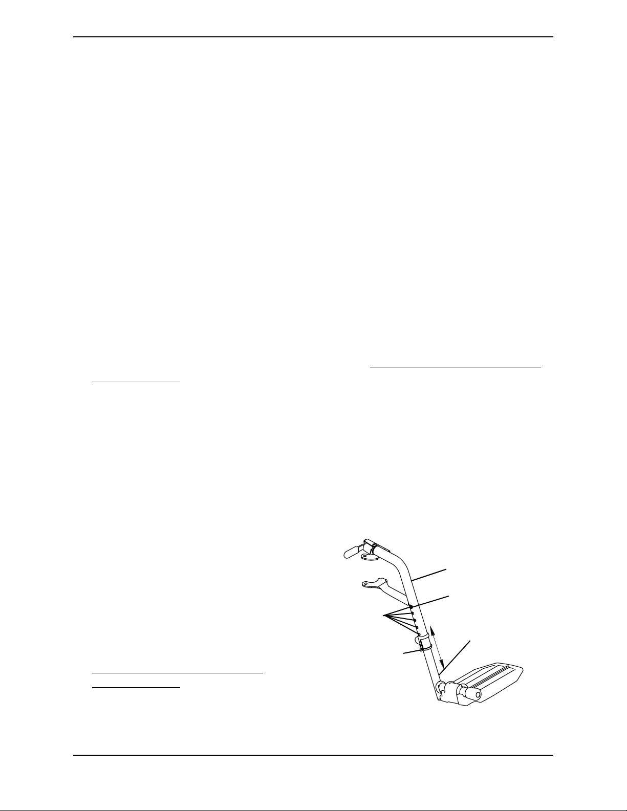
Raising/Lowering the Legrest Assembly
WARNING
Ensure hands and fingers are clear of elevating legrest mechanism before pushing
release lever to lower the elevating legrest. Otherwise injury may occur due to
pinch points.
The wheelchair user’s leg MUST be supported by an assistant before attempting to
lower legrest.
P9000™ XDT 36 Part No. 1118386
SECTION 6—FRONT RIGGINGS
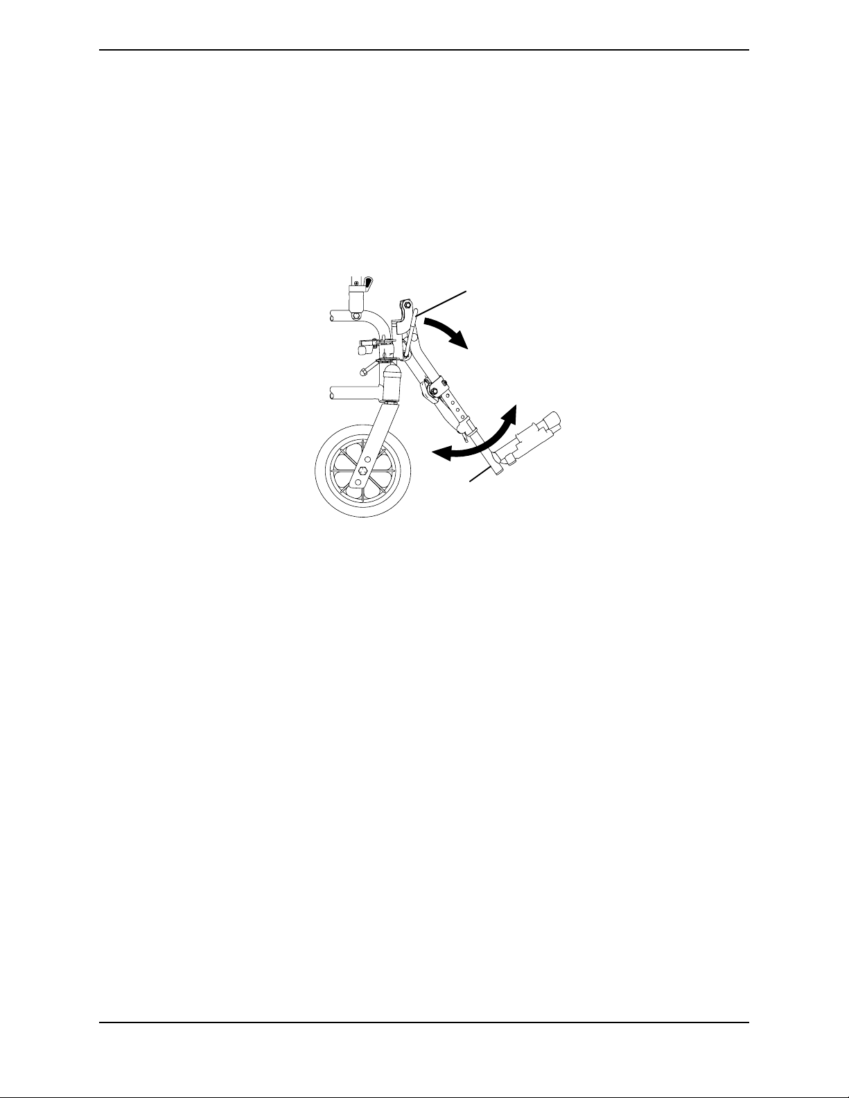
NOTE: For this procedure, refer to FIGURE 6.4.
1. To raise the elevating legrest, the assistant should hold the support tube and raise
elevating legrests until the desired height is obtained.
2. To lower the elevating legrest, perform the following:
A. Support user leg with one (1) hand.
B. Push release lever downward with other hand.
C. Gently, lower user leg down and rest against the legrest.
Release
Lever
Support
Tube
FIGURE 6.4 Raising/Lowering the Legrest Assembly
Part No. 1118386 37 P9000™ XDT
SECTION 7—ARMS
SECTION 7—ARMS
WARNING
After ANY adjustments, repair or service and BEFORE use, make sure that all
attaching hardware is tightened securely - otherwise injury or damage may result.
Before performing any maintenance, adjustment or service verify that on/off switch
on the joystick is in the off position.
Adjusting Armrest Height
WARNING
Make sure the height adjustment lever is in the locked position before using the
wheelchair.
NOTE: For this procedure, refer to FIGURE 7.1.
1. Unlock the armrest by flipping the height adjustment lever on the top front of the
armrest to the up (horizontal) position.
2. Adjust armrest to one (1) of five (5) positions.
NOTE: Height adjustment lever MUST be in the unlocked position when placing armrest into the
arm assembly.
3. Lock the armrest by pressing the height adjustment lever into the down (vertical)
position when the desired armrest height is achieved.
4. Repeat STEPS 1-3 for other armrest.
Armrest
Locked
(Vertical)
Unlocked
(Horizontal)
Height Adjustment Lever
FIGURE 7.1 Adjusting Armrest Height
P9000™ XDT 38 Part No. 1118386

SECTION 7—ARMS
Swing-Back Arms
WARNING
Make sure the armrest release lever is in the locked position before using the wheelchair.
NOTE: For this procedure, refer to FIGURE 7.2.
1. Unlock the swing-back arms by rotating the armrest release lever towards the outside
of the wheelchair.
2. Pull the front of the swing-back arm straight up/out of the arm socket and towards the
rear of the wheelchair.
3. To use the swing-back arm, push the swing-back arm towards the front of the
wheelchair and then downward into the arm socket.
NOTE: Armrest release lever MUST be in the unlocked position when placing armrest into the
arm sockets.
4. Lock the swing-back arms by rotating the armrest release lever towards the inside of
the wheelchair.
Swing Back Arm
Rear
FIGURE 7.2 Swing-Back Arms
Replacing Armrest Pad
NOTE: For this procedure, refer to FIGURE 7.3
1. Remove the mounting screws that
secure the armrest pad to the armrest
assembly.
2. Replace armrest pad and securely
tighten with the existing mounting
screws.
Front
Armrest Release Lever
Arm Socket
Armrest Pad
Armrest Assembly
Mounting
Screws
FIGURE 7.3 Replacing Armrest Pad
Part No. 1118386 39 P9000™ XDT
SECTION 8—SEAT AND BACK
SECTION 8—SEAT AND BACK
WARNING
After ANY adjustments, repair or service and BEFORE use, make sure that all
attaching hardware is tightened securely - otherwise injury or damage may result.
Before performing any maintenance, adjustment or service verify that on/off switch
on the joystick is in the off position.
Replacing the Seat Upholstery
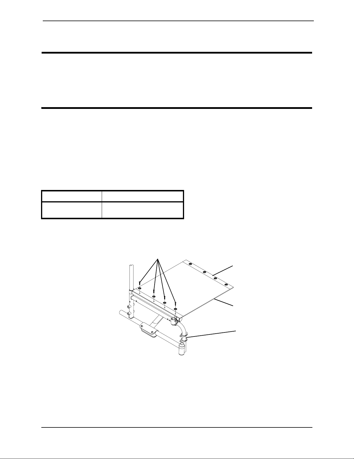
NOTE: For the following procedure, refer to FIGURE 8.1.
1. Remove the mounting screws that secure the existing seat upholstery to the
wheelchair frame.
NOTE: Refer to the following table to determine the number of mounting screws for each seat
depth.
SEAT DEPTH NUMBER OF SCREWS
16 inch
18 inch
2. Remove the existing seat upholstery from the wheelchair frame.
3. Install new seat upholstery by reversing Steps 1-2.
8
10
Mounting Screws
16-inch Seat Depth
Seat Upholstery
Wheelchair Frame
FIGURE 8.1 Replacing the Seat Upholstery
P9000™ XDT 40 Part No. 1118386

SECTION 8—SEAT AND BACK
Replacing the Back Upholstery
NOTE: For the following procedure, refer to FIGURE 8.2.
1. Flip swing back arms up and out of the way. Refer to Swing-Back Arms on page 39.
2. Remove the six (6) mounting screws and washers that secure the EXISTING back
upholstery to the back canes.
3. Cut the tie wraps that secure the existing back upholstery to the wheelchair frame.
4. Securely tighten the NEW back upholstery to the back canes with the six (6) mounting
screws and washers starting with the top hole of the back cane.
5. Install two (2) NEW tie wraps through the bottom holes of the upholstery to the
bottom of the back upholstery to the back canes.
6. Flip swing-back arms down for use. Refer to Swing-Back Arms on page 39.
Mounting Screws
Washers
Tie Wraps
Back Upholstery
Mounting Screws
FIGURE 8.2 Replacing the Back Upholstery
Back Cane
Washers
Part No. 1118386 41 P9000™ XDT

SECTION 8—SEAT AND BACK
Adjusting the Back Height
NOTE: For this procedure, refer to FIGURE 8.3.
NOTE: Back canes must be adjusted to the same height.
1. Remove the two (2) mounting screws and locknuts that secure the two (2) back canes
to the wheelchair frame.
2. Reposition the back canes to the desired height adjustment position.
3. Reinstall the mounting screws and locknuts that secure the back canes to the
wheelchair frame and securely tighten.
Back Cane
Wheelchair Frame
Mounting Screw
Back Height (in inches)
*HOLE#
HEIGHT 17 18 19
12 3
Locknut
*NOTE: Holes numbered from bottom to top for reference only. (There are no numbers on the
back canes or wheelchair frame.)
FIGURE 8.3 Adjusting the Back Height
P9000™ XDT 42 Part No. 1118386

SECTION 8—SEAT AND BACK
Replacing Seat Positioning Strap
NOTE: For this procedure, refer to FIGURE 8.4.
1. If necessary, remove the seat cushion from the seat upholstery.
2. Remove the two (2) rear phillips screws and washers that secure the seat upholstery
and seat positioning strap to the crossbraces.
3. Remove the two (2) halves of the seat positioning strap from the crossbraces.
4. Position the two (2) new seat positioning strap halves between the seat upholstery and
the crossbraces.
5. Reinstall the rear phillips screws and washers that secure the seat upholstery and seat
positioning strap to the crossbraces.
NOTE: Washer is positioned on top of seat upholstery.
6. If necessary, reinstall the seat cushion onto the seat upholstery.
Seat Positioning Strap
FIGURE 8.4 Replacing Seat Positioning Strap
Washer
Crossbrace
Rear Phillips Screw
Seat Upholstery
Part No. 1118386 43 P9000™ XDT

SECTION 9—JOYSTICK
SECTION 9—JOYSTICK
WARNING
After ANY adjustments, repair or service and BEFORE use, make sure that all
attaching hardware is tightened securely - otherwise injury or damage may result.
Before performing any maintenance, adjustment or service verify that On/Off
switch on the joystick is in the OFF position.
Preparing the Joystick for Use
NOTE: For this procedure, refer to FIGURE 9.1.
NOTE: The joystick is factory installed on the right side of the wheelchair. To reposition the joystick
onto the left side of the wheelchair, refer to Repositioning the Joystick
should be repositioned by a qualified technician.
1. Turn the adjustment lock lever to release the joystick mounting tube from the
mounting bracket.
on page 45. The joystick
2. Slide joystick mounting tube to the desired position.
3. Turn the adjustment lock lever to secure the joystick mounting tube in the mounting
bracket.
Mounting Bracket
Joystick Mounting Tube
Adjustment Lock Lever
FIGURE 9.1 Preparing the Joystick for Use
P9000™ XDT 44 Part No. 1118386

SECTION 9—JOYSTICK
Repositioning the Joystick
NOTE: For this procedure, refer to FIGURE 9.2.
NOTE: Before starting this procedure, it may be necessary to snip the tie-wraps (not shown in
FIGURE 9.2) securing the joystick control cord to the wheelchair. Before snipping the tie-wraps,
note the way the cord is secured to the chair so that it can be re-secured in the same way at the end
of the procedure.
1. Turn the adjustment lock lever to release the joystick mounting tube from the
mounting bracket.
2. Remove the joystick from the wheelchair.
3. Remove the three (3) hex screws that secure both halves of the mounting bracket to the
arm tube.
4. Reposition mounting bracket on opposite arm tube ensuring the threaded plate of the
mounting bracket is on the inside of the arm tube.
5. Using the three (3) hex mounting screws and washers, secure both halves of the
mounting bracket to the arm tube.
6. Slide the joystick mounting tube through the mounting bracket to the desired
position.
7. Turn the adjustment lock lever to secure the joystick mounting tube into the mounting
bracket.
8. If the tie-wraps securing the joystick control cord to the wheelchair were snipped at
the beginning of this procedure, re-secure the cord to the wheelchair with new
tie-wraps in such a way that the control cord will not be pinched or cut during
operation of the wheelchair.
Mounting Bracket
(Threaded Plate)
Washers
Arm Tube
Hex Mounting
Screws
Adjustment
Lock Lever
Mounting
Bracket
Joystick
Joystick
Mounting
Tube
FIGURE 9.2 Repositioning the Joystick
Part No. 1118386 45 P9000™ XDT

SECTION 10—CASTER
SECTION 10—CASTER
WARNING
After ANY adjustments, repair or service and BEFORE use, make sure that all
attaching hardware is tightened securely - otherwise injury or damage may result.
Before performing any maintenance, adjustment or service verify that ON/OFF
switch on the joystick is in the OFF position.
CAUTION
As with any vehicle, the wheels, casters and tires should be checked periodically for
cracks and wear and should be replaced.
Adjusting Forks
NOTE: For this procedure, refer to FIGURE 10.1.
1. Remove the dust cover from the caster headtube.
2. To properly tighten caster journal system and guard against flutter, perform the
following check:
A. Remove battery boxes and battery tray from wheelchair. Refer to
Removing/Installing the Battery Boxes on page 50 and Installing/Removing
Battery Tray on page 51.
B. Tip back the wheelchair to floor.
C. Pivot both forks and casters to top of their arc simultaneously.
D. Let casters drop to bottom of arc
(wheels should swing once to
one-side, then immediately rest in a
straight downward position).
E. Adjust locknuts according to
freedom of caster swing.
3. Test wheelchair for maneuverability.
4. Readjust locknuts if necessary, and
repeat STEPS 1-3 until correct.
5. Snap dust cover into the caster
headtube.
Dust Cover
Locknut
Nylon
Washer
Caster
Headtube
Fork
Caster
FIGURE 10.1 Adjusting Forks
P9000™ XDT 46 Part No. 1118386

SECTION 11—BATTERIES
SECTION 11—BATTERIES
WARNING
After ANY adjustments, repair or service and BEFORE use, make sure that all
attaching hardware is tightened securely - otherwise injury or damage may result.
Before performing any maintenance, adjustment or service verify that on/off switch
on the joystick is in the off position.
When to Charge Batteries
NOTE: For this procedure, refer to FIGURE 11.1.
Recharge the batteries frequently. Do not wait until the battery charge is low to recharge.
A battery’s life is extended if the charge level is maintained well above a low condition.
The information gauge is the primary source of user feedback. The true
state-of-battery-charge notification is as follows:
• Any GREEN LED lit: Batteries are at full or well charged.
• Only AMBER and RED LEDs lit: Batteries are moderately charged. Recharge before
undertaking a long trip.
• Only RED LED lit: Battery charge is low. Recharge as soon as possible.
NOTE: Accurate readings are displayed when the joystick is in neutral.
Information Gauge
FIGURE 11.1 When to Charge Batteries
Part No. 1118386 47 P9000™ XDT

SECTION 11—BATTERIES
Charging Batteries
WARNING
Never attempt to recharge the batteries by attaching cables directly to the battery
terminals or clamps. Use the recharging plug located on the front of the joystick.
DO NOT attempt to recharge the batteries and operate the power wheelchair at
the same time.
During use and charging, unsealed batteries will vent hydrogen gas which is
explosive in the right concentration with air. Follow the manufacturer's charging
instructions.
CAUTION
Always charge new batteries before initial use or battery life will be reduced.
NOTE: As a general rule, batteries should be recharged daily to assure the longest possible life and
minimize the required charging time. Plan to recharge the batteries when it is anticipated the
wheelchair will not be used for a long period of time.
The range per battery charge using recommended batteries should be approximately 5 to
9 hours of typical operation. Extensive use on inclines may substantially reduce per
charge mileage.
Description and Use of Battery Chargers
The charger automatically reduces the charge from an initially high rate to a zero reading
at a fully charged condition. If left unattended, the charger should automatically shut-off
when full charge is obtained.
Some basic concepts which will help you understand this automatic process are:
The amount of electrical current drawn within a given time to charge a battery is called
“charge rate”. If, due to usage, the charge stored in the battery is low, the charge rate is
high, as indicated by the green light on the charger. Initially, the green light will stay
illuminated for a short period of time followed by a longer period of off time. As a charge
builds up, the charge rate is reduced, and the green light will stay illuminated for a longer
period of time followed by a shorter off time.
NOTE: If performing the charging procedures independently, READ and CAREFULLY follow the
individual instructions for each charger (supplied or purchased).
NOTE: If charging instructions are not supplied, consult a qualified service technician for proper
procedures. Required items:
TOOLS QUANTITY COMMENTS
Battery charger
*Extension cord
1
1
Supplied
Not Supplied
*NOTE: 3-prong plug, 15 ampere current rating; industrial type
P9000™ XDT 48 Part No. 1118386

Connecting the Battery Charger
NOTE: For this procedure, refer to FIGURE 11.2.
1. Attach the battery charger connector to
the charger port on the joystick.
2. Plug the charger’s AC power cord, or
extension, into the grounded 120 VAC
wall outlet.
3. Wait until charging is complete.
NOTE: If the batteries need to be charged more
often or take longer to charge than normal, they
may need to be replaced. Contact an Invacare
dealer for service.
Replacing the Batteries
SECTION 11—BATTERIES
Charger
Port
FIGURE 11.2 Connecting the Battery
Charger
WARNING
Most batteries are not sold with instructions. However, warnings are frequently
noted on the cell caps. Read them carefully, otherwise injury or damage can occur.
The use of rubber gloves and chemical goggles or face shields is recommended
when working with batteries.
NOTE: Invacare recommends that both batteries be replaced if one (1) battery is defective.
Recommended Battery Types
WARNING
The warranty and performance specifications contained in this manual are based on
the use of deep cycle gel cell or sealed lead acid batteries. Invacare strongly
recommends their use as the power source for this unit.
CAUTION
Failure to use the correct battery size and/or voltage may cause damage to your
wheelchair and give you unsatisfactory performance.
CHAIR SEAT
WIDTH
18- inches
18-inches
2
2
QTY VOLTS BATTERY
SIZE
12
12
U1
Group 22NF
REMARKS
Deep Cycle
Deep Cycle
1. Remove the battery boxes and tray from the wheelchair. Refer to Removing/Installing
the Battery Boxes on page 50 and Installing/Removing Battery Tray on page 51.
Part No. 1118386 49 P9000™ XDT

SECTION 11—BATTERIES
2. Remove the existing batteries from the battery boxes. Refer to Installing/Removing
Batteries Into/From Battery Boxes on page 52.
3. Clean the new battery terminals.
4. Install the new batteries into the battery boxes. Refer to Installing/Removing Batteries
Into/From Battery Boxes on page 52.
5. Install the battery boxes and tray onto the wheelchair. Refer to Removing/Installing
the Battery Boxes on page 50 and Installing/Removing Battery Tray on page 51.
Cleaning Battery Terminals
WARNING
DO NOT allow the liquid in the battery to come in contact with skin, clothes or
other possessions. It is a form of acid and harmful or damaging burns may result.
Should the liquid touch your skin, wash the area immediately and thoroughly with
cool water. In serious cases or if eye contact is made, seek medical attention
IMMEDIATELY.
NEVER smoke or strike a match near batteries. If the caps of the battery cells are
removed, NEVER look directly into them while charging batteries.
1. Examine battery clamps and terminals for corrosion.
2. Verify that the plastic caps are in place over the battery cell holes.
3. Clean the terminals and inside the battery clamps by using a battery cleaning tool,
wire brush, or medium grade sand paper.
NOTE: When done, these areas should be shiny, not dull.
4. Carefully dust off all metal particles.
Removing/Installing the Battery Boxes
WARNING
NEVER unplug the battery cables by pulling on the wires. Unplug the battery cables
by pulling on the connector ONLY. Otherwise injury or damage may result.
NOTE: For this procedure, refer to FIGURE 11.3.
NOTE: To remove the battery boxes from the wheelchair, reverse the following procedure.
1. Verify that the on/off switch on the joystick is in the off position.
2. Place the front battery box onto the battery tray and connect controller connector to
the front battery box. Refer to Electronics Manual (P/N 1110532).
3. Slide front battery box toward the front of the wheelchair.
P9000™ XDT 50 Part No. 1118386
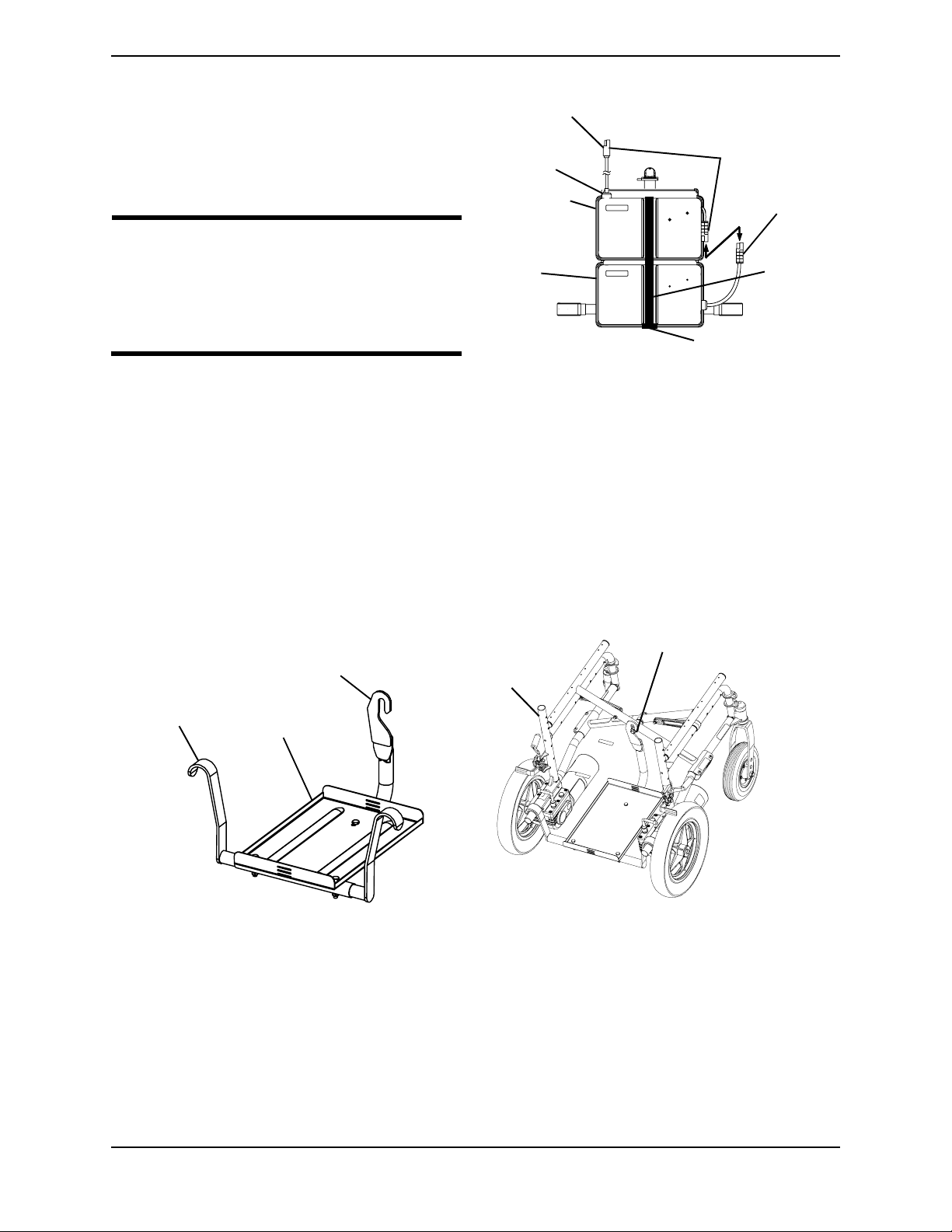
SECTION 11—BATTERIES
4. Place rear battery box onto the battery
tray and connect the rear battery box to
the front battery box.
5. Connect the front battery box to the
controller.
WARNING
The battery box retaining strap MUST
be fastened securely and adjusted properly to hold battery boxes in place
To Controller
Battery
Tray
Front
Battery
Box
Rear
Battery
Box
Front Battery
Box Connectors
Rear Battery
Box Connector
before using the wheelchair.
Retaining Strap Clip
6. Connect the battery box retaining strap
clip together and adjust if necessary.
FIGURE 11.3 Removing/Installing the
Battery Boxes
Installing/Removing Battery Tray
NOTE: For this procedure, refer to FIGURE 11.4.
NOTE: To remove the battery tray from the wheelchair, reverse the following procedure.
Retaining
Strap
1. Attach the key slot bracket located at the front of the battery tray over the crossbrace
bolt bushing under the seat upholstery of the wheelchair.
2. Attach the hanger brackets to the wheelchair frame.
Crossbrace Bolt Bushing
Hanger
Bracket
Key Slot Bracket
Battery Tray
Wheelchair Frame
FIGURE 11.4 Installing/Removing Battery Tray
Part No. 1118386 51 P9000™ XDT

SECTION 11—BATTERIES
Installing/Removing Batteries Into/From Battery Boxes
WARNING
Make sure power to the wheelchair is OFF before performing this procedure.
The use of rubber gloves and chemical goggles or face shields is recommended
when working with batteries.
Invacare strongly recommends that battery installation and battery replacement
ALWAYS be done by a qualified technician.
After ANY adjustments, repair or service and BEFORE use, make sure all attaching
hardware is tightened securely - otherwise injury or damage may result.
NOTE: For this procedure, refer to FIGURE 11.5.
NOTE: For changing or removing/installing the battery boxes, refer to Removing/Installing the
Battery Boxes on page 50.
NOTE: To remove the battery(ies) from the battery box(es), reverse the following procedure.
NOTE: Have the following tools available:
TOOL QTY COMMENTS
Battery Lifting Strap 1 See following note.
1/2-inch (6 pt.) Box Wrench 1 Not Supplied
7/16-inch (6pt) Box Wrench 1 Not Supplied
3/8-inch (6pt) Box Wrench 1 Not Supplied
Diagonal Cutters 1 Not Supplied
NOTE: The battery lifting strap supplied is for Group 22NF batteries ONLY. Refer to the battery
manufacturer for the proper lifting strap and/or battery tools for U1 battery removal/installation.
WARNING
ALWAYS use a battery lifting strap when lifting a battery. It is the most convenient
method and assures that the battery acid will not spill. It also helps to prolong the
life of the battery. The battery lifting strap supplied is for Group 22NF batteries
ONLY. Refer to the battery manufacturer for the proper lifting strap and/or battery
tools for U1 battery removal/installation.
DO NOT tip the batteries. Keep the batteries in an upright position.
NOTE: If there is battery acid in the bottom or on the sides of the battery box(es) or battery(ies),
apply baking soda to these areas to neutralize the battery acid. Before reinstalling the new or
existing battery(ies), clean the baking soda from the battery box(es) or battery(ies).
NOTE: When securing battery lifting strap to battery, observe polarity markings located on the
ends of the battery lifting strap, (+) side to POSITIVE (+) battery terminal/post and (-) side to
NEGATIVE (-) battery terminal/post.
P9000™ XDT 52 Part No. 1118386
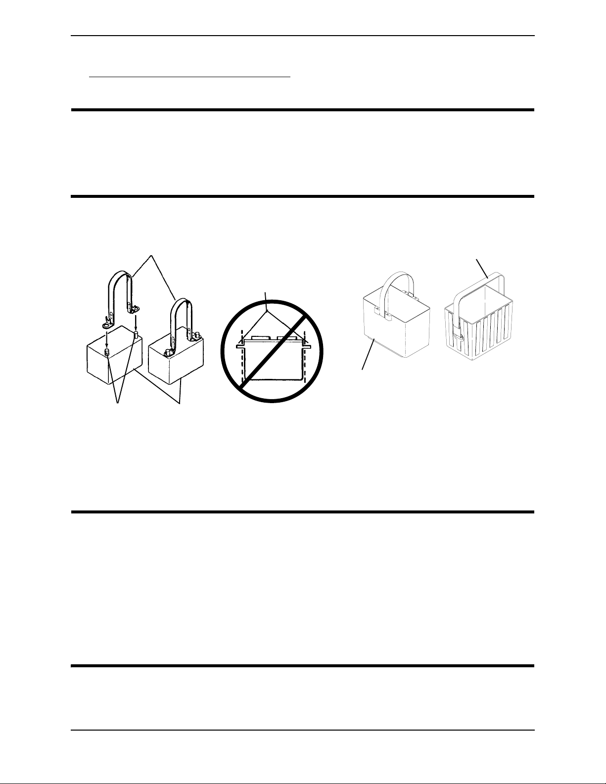
SECTION 11—BATTERIES
1. If necessary, remove the battery boxes from the wheelchair. Refer to
Removing/Installing the Battery Boxes on page 50.
2. Secure the battery lifting strap to battery terminal(s)/post(s).
CAUTION
Some battery manufacturers mold a carrying strap and/or hold down flanges
directly into the battery case. Batteries which interfere with the battery box cannot
be used for these applications. Attempting to “wedge” a battery into a battery box
may damage the box and/or the battery.
3. Place batteries into battery box bottom.
Battery Lifting Strap
Molded Carrying Strap or
Hold Down Flanges
Battery
Battery
Terminal(s)/Post(s)
Group 22NF ONLY
FIGURE 11.5 Installing/Removing Batteries Into/From Battery Boxes
Connecting Battery Cables
WARNING
U1 Battery
Box Bottom
22NF Battery
Box, Bottom
The use of rubber gloves and chemical goggles or face shields is recommended
when working with batteries.
NEVER allow any of your tools and/or battery cable(s) to contact BOTH battery
terminal(s)/post(s) at the same time. An electrical short may occur and serious
personal injury or damage may occur.
The correct battery terminal configurations shown in FIGURE 11.6 MUST be used.
Batteries that have the reversed terminal configuration MUST NOT be used. Otherwise, serious injury or damage may occur.
Part No. 1118386 53 P9000™ XDT
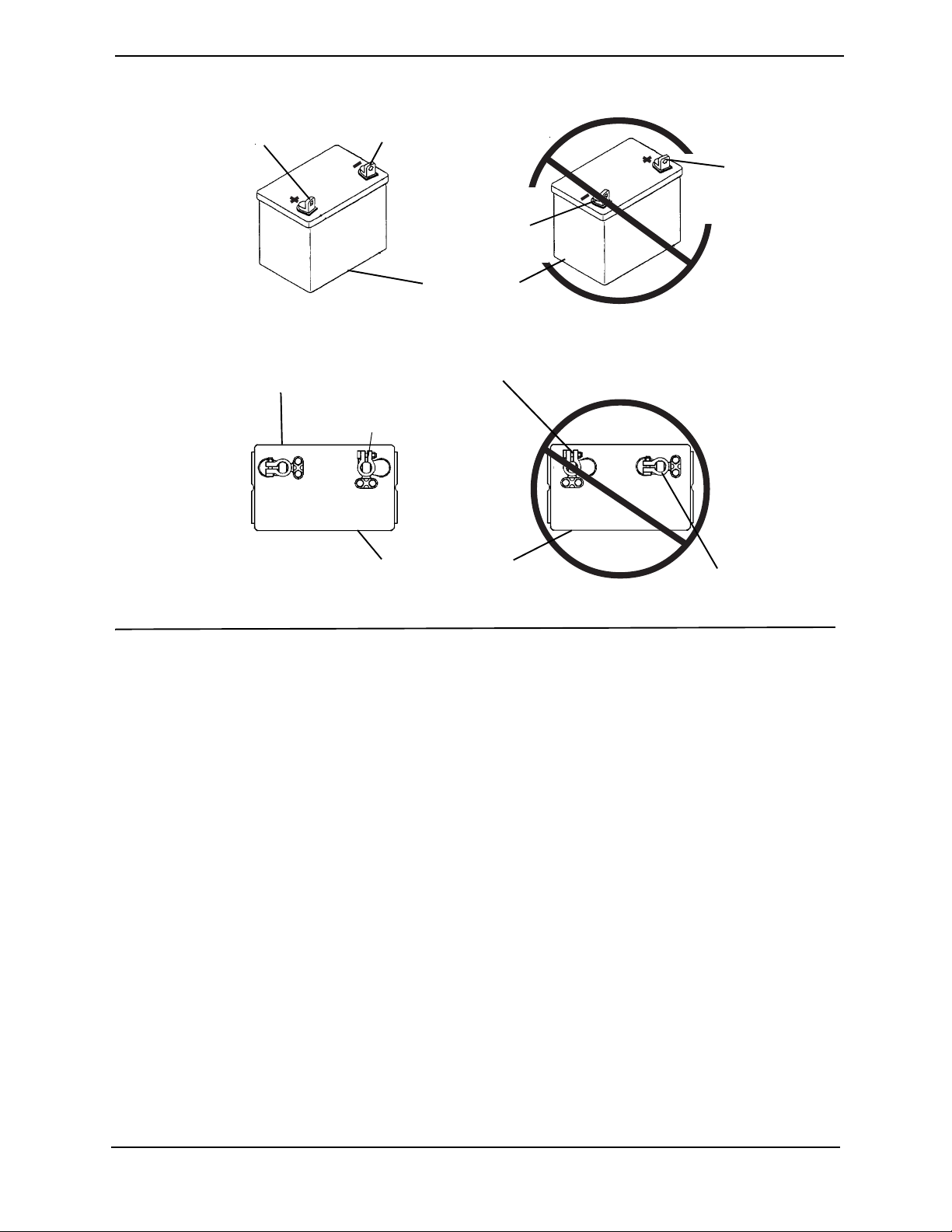
SECTION 11—BATTERIES
POSITIVE (+)
Terminal/Post
DO NOT USE
NEGATIVE (-)
Terminal/Post
POSITIVE (+)
Terminal/Post
NEGATIVE (-)
Terminal/Post
U1 Batteries
POSITIVE (+) Terminal/Post
(Note position of clamp)
NEGATIVE (-)
Terminal/Post and Clamp
NEGATIVE (-)
Terminal/Post and Clamp
Group 22NF Batteries
DO NOT USE
POSITIVE (+) Terminal/Post
(Note position of clamp)
FIGURE 11.6 Connecting Battery Cables
Perform one (1) of the following methods for connecting the battery cable(s):
• Dual U1 Batteries - Use direct mount method described on page 54. Refer to
FIGURE 11.7.
• Dual Group 22NF Batteries with Mounting Holes in the Terminal(s)/Post(s) - Use
direct mount method described on page 54. Refer to FIGURE 11.7.
• Dual Group 22NF Batteries without Mounting Holes in the Terminal(s)/Post(s) - Use
battery clamp method described on page 57. Refer to FIGURE 11.8 and FIGURE 11.9.
Direct Mount Method
NOTE: For this procedure, refer to FIGURE 11.7.
1. Install battery terminal cap(s) onto battery cable(s):
A. Dual U1 Batteries
i. ORANGE battery terminal cap onto RED battery cable.
ii. GREY battery terminal cap onto BLACK battery cable.
B. Dual Group 22NF BATTERIES
i. RED battery terminal cap onto RED battery cable.
ii. BLACK battery terminal cap onto BLACK battery cable.
P9000™ XDT 54 Part No. 1118386

SECTION 11—BATTERIES
CAUTION
When connecting the battery cables to the battery(ies), the battery cable(s) MUST
be connected to the battery terminal(s)/post(s) as shown in Detail “A” or Detail
“B” of FIGURE 11.7 (depending on battery type). Otherwise, damage to the battery
cable may result when installing battery terminal caps.
2. Connect battery cable(s) to battery(ies) terminal(s)/post(s) as shown in Detail “A” or
Detail “B” of FIGURE 11.7, depending on battery type:
A. NEGATIVE (-) BLACK battery cable to NEGATIVE (-) battery terminal/post.
B. POSITIVE (+) RED battery cable to POSITIVE (+) battery terminal/post.
3. Secure the battery cable(s)/ring terminal(s) to the battery terminal(s)/post(s), BLACK
to NEGATIVE (-) and RED to POSITIVE (+), with the provided 1/4-20 x 7/8-inch hex
flange screw and hex flange locknut as shown in Detail “A” or Detail “B” of
FIGURE 11.7, depending on battery type. Securely tighten.
4. Verify all battery cable(s)/ring terminal(s) are correctly installed and securely
tightened.
5. Slide terminal cap(s) down battery cable(s) and onto battery clamps.
6. Using the 11½-inch long tie-wrap, secure each terminal cap in place (Detail “A” or
Detail “B” of FIGURE 11.7).
NOTE: It will be necessary to trim excess tie-wrap in order to install the battery box top(s).
7. Install the battery box top(s).
Part No. 1118386 55 P9000™ XDT
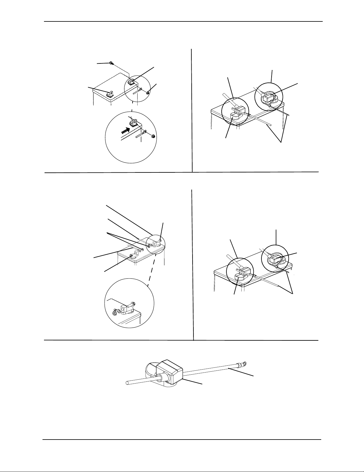
SECTION 11—BATTERIES
Detail “A” - Dual UI Batteries
1/4-20 x 7/8-Inch
Hex Flange Screw
POSITIVE (+)
Terminal/Post
CONNECT
CABLE RING
TERMINAL TO
THIS SIDE OF
TERMINAL/POST
POSITIVE (+)
Terminal/Post
POSITIVE (+) Red Cable
1/4-20 Hex
Flange Locknuts
NEGATIVE (-)
Black Cable
NEGATIVE (-)
Terminal/Post
1/4-20
Hex
Flange
Locknut
Detail “B” - Dual Group 22 NF Batteries
1/4-20 x 7/8-Inch
Hex Flange Screw
POSITIVE (+)
Terminal/Post
ORANGE
Terminal Cap
NEGATIVE (-)
Terminal/Post
NEGATIVE (-)
Terminal/Post
Tie-Wraps
POSITIVE (+)
Terminal/Post
GREY
Terminal
Cap
RED
Terminal
Cap
NEGATIVE (-)
Terminal/Post
CONNECT
CABLE TO
TERMINAL AS
BLACK
Terminal
Cap
Tie-Wraps
SHOWN.
Detail “C” - Installing Battery Terminal Cap onto Battery Cable
Cable
Terminal Cap
NOTE: For clarity, only one (1) cable and terminal cap are shown. Both caps install in the
same manner.
FIGURE 11.7 Connecting Battery Cables - Direct Mount Method
P9000™ XDT 56 Part No. 1118386
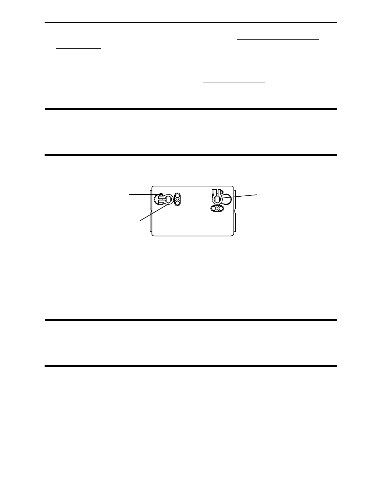
SECTION 11—BATTERIES
8. Install the battery box(es) into the wheelchair. Refer to Removing/Installing the
Battery Boxes on page 50.
NOTE: New battery(ies) MUST be fully charged before using, otherwise the life of the battery(ies)
will be reduced.
9. If necessary, charge the battery(ies). Refer to Charging Batteries on page 48.
Battery Clamp Method
CAUTION
The battery clamp of the POSITIVE (+) battery terminal/post MUST be mounted in
the position shown in FIGURE 11.8. Otherwise, the battery box top cannot be
installed properly.
NOTE: For this procedure, refer to FIGURE 11.8 and FIGURE 11.9.
Hex Nut
POSITIVE (+) Terminal/Post
(Note position of clamp.)
NEGATIVE (-) Terminal/Post
and Clamp
FIGURE 11.8 Connecting Battery Cables - Battery Clamp Method
1. Perform one (1) of the following:
• If the battery clamp of the POSITIVE (+) battery terminal/post is NOT mounted in
the orientation shown in FIGURE 11.8, perform the following:
i. Loosen the hex nut that secures the battery clamp to the POSITIVE (+) battery
terminal/post.
CAUTION
When tightening the clamps, always use a box wrench. Pliers will “round off” the
nuts. NEVER wiggle the battery terminal(s)/post(s) when tightening. The battery
may become damaged.
ii. Remove the battery clamp from the POSITIVE (+) battery terminal/post.
iii. Reposition the battery clamp on the POSITIVE (+) battery terminal/post as
shown in FIGURE 11.8.
iv. Securely tighten the hex nut that secures the battery clamp to the positive (+)
battery terminal/post.
• If the battery clamp on the POSITIVE (+) battery terminal/post is positioned as
shown in FIGURE 11.8, proceed to STEP 2.
Part No. 1118386 57 P9000™ XDT

SECTION 11—BATTERIES
2. Install battery clamp covers onto battery cables (Detail “C” of FIGURE 11.9):
A. RED battery clamp cover onto RED battery cable.
B. BLACK battery clamp cover onto BLACK battery cable.
CAUTION
When connecting the battery cable/ring terminal(s) to the battery(ies) clamp(s),
the battery cable(s) MUST be connected in the position shown in Detail “A” of
FIGURE 11.9. Otherwise, damage may occur to the battery cable and/or battery
clamp covers.
3. Connect battery cable(s) to battery(ies) terminal(s)/post(s) as shown in Detail “A” of
FIGURE 11.9:
A. NEGATIVE (-) BLACK battery cable/ring terminal between the mounting plate
and battery clamp of NEGATIVE (-) battery terminal/post.
B. POSITIVE (+) RED battery cable/ring terminal between the mounting plate and
battery clamp of POSITIVE (+) battery terminal/post.
4. Secure the battery cable(s)/ring terminal(s) to the battery clamp(s), BLACK to
NEGATIVE (-) and RED to POSITIVE (+), with existing hex screws as shown in Detail
“A” of FIGURE 11.9. Securely tighten.
5. Verify battery cable ring terminal(s) are correctly installed and securely tightened.
6. Slide battery clamp covers down battery cables and onto battery terminals as shown
in Detail “B” of FIGURE 11.9.
7. Using 11½-inch long tie-wraps, secure each terminal cap in place as shown in Detail
“B” of FIGURE 11.9.
NOTE: It will be necessary to trim excess tie-wrap in order to install the battery box top(s).
8. Install the battery box top(s).
9. Install the battery box(es) into the wheelchair. Refer to Removing/Installing the
Battery Boxes on page 50.
NOTE: New battery(ies) MUST be fully charged BEFORE using, otherwise the life of the
battery(ies) will be reduced.
10. If necessary, charge the battery(ies). Refer to Charging Batteries
on page 48.
P9000™ XDT 58 Part No. 1118386

Exploded View
SECTION 11—BATTERIES
POSITIVE (+)
RED Cable
NEGATIVE (-)
BLACK Cable
Group 22NF Battery
Detail “A” - Top View
Fuse box placement when
box top is installed
POSITIVE (+)
Terminal/Post and
Clamp
POSITIVE (+)
RED Cable
NEGATIVE (-)
Terminal/Post and
Clamp
NEGATIVE (-)
Terminal/Post
Detail “B” - Tie-Wraps
NEGATIVE (-)
Terminal/Post
Tie-Wraps
Hex Screw
Mounting Plate
Clamp
POSITIVE (+)
Terminal/Post
POSITIVE (+)
Terminal/Post
RED Clamp
Cover
NEGATIVE (-)
BLACK Cable
Group 22NF Battery
Group 22NF
Battery
Fuse Box
BLACK Clamp
Cover
Detail “C” - Installing Battery Clamp Cover
Clamp
Cable
Cover
NOTE: For clarity, only one (1) cable and clamp cover are shown. Both clamp covers install in
the same manner.
FIGURE 11.9 Connecting Battery Cables - Battery Clamp Method
Part No. 1118386 59 P9000™ XDT

SECTION 11—BATTERIES
Replacing Battery Box Retaining Strap
WARNING
The battery box retaining strap MUST be fastened securely and adjusted properly
to hold battery boxes in place before using the wheelchair.
NOTE: For this procedure, refer to FIGURE 11.10.
1. Remove the battery boxes from the wheelchair. Refer to Removing/Installing the
Battery Boxes on page 50.
2. Remove the battery tray from the wheelchair. Refer to Installing/Removing Battery
Tray on page 51.
WARNING
The retaining strap MUST be fed through the adjustable end of the battery box
retaining strap buckle as shown in FIGURE 11.9.
NOTE: Take note of the position and orientation of the battery box retaining strap as it passes
through the slots of the battery tray and the adjustable end of the battery box retraining strap
buckle.
3. Feed the existing battery box retaining strap through the adjustable end of the battery
box retaining strap buckle.
4. Feed the existing battery box retaining strap through the slots in the battery box tray.
5. Install the new battery box retaining strap by reversing STEPS 3 and 4.
6. Reinstall the battery tray from the wheelchair. Refer to Installing/Removing Battery
Tray on page 51.
7. Reinstall the battery boxes from the wheelchair. Refer to Removing/Installing the
Battery Boxes on page 50.
Adjustable End
Retaining
Strap Buckle
Retaining
Strap
Battery Tray
Slots
Retaining
Strap
Slots
Battery
Tray
Retaining Strap
FIGURE 11.10 Replacing Battery Box Retaining Strap
P9000™ XDT 60 Part No. 1118386

SECTION 12—CLUTCH/MOTOR LOCK
SECTION 12—CLUTCH/MOTOR
LOCK
WARNING
After ANY adjustments, repair or service and BEFORE use, make sure all attaching
hardware is tightened securely - otherwise injury or damage may result.
Engaging/Disengaging the Clutches
WARNING
DO NOT engage or disengage the clutches until the power is off.
NOTE: For this procedure, refer to FIGURE 12.1.
The clutch engagement/disengagement allows freewheeling or joystick controlled
operation. Freewheeling allows an attendant to maneuver the wheelchair without power.
To engage/disengage the clutches:
1. Locate the clutch handles on motors.
WARNING
If clutch handles are forced to engage in the wrong direction as shown in
FIGURE 12.1, the motors will be damaged and will need to be replaced.
2. Perform one (1) of the following:
• To Engage: turn the clutch handles until they are pointing towards the rear of the
wheelchair. NEVER try to turn the clutch handles towards the front of the wheelchair.
• To Disengage: turn the clutch handles until they are pointing towards the rear wheels.
NEVER try to turn the clutch handles towards the inside of the wheelchair.
Top View Of Wheelchair
Disengaged (Toward rear wheels)
Engaged (Toward
rear of wheelchair)
Clutch Handle
Clutch Handle
NOTE: NEVER force clutch
handles in these directions.
FIGURE 12.1 Engaging/Disengaging the Clutches
Part No. 1118386 61 P9000™ XDT

SECTION 13—WHEEL LOCKS
SECTION 13—WHEEL LOCKS
WARNING
After ANY adjustments, repair or service and BEFORE use, make sure all attaching
hardware is tightened securely - otherwise injury or damage may result.
Installing/Adjusting/Using the Wheel Locks
NOTE: For this procedure, refer to FIGURE 13.1.
Installing/Adjusting
NOTE: Before adjusting or replacing the wheel lock assemblies, ensure that the tires are inflated to
the recommended psi on the side wall of tire.
NOTE: If necessary, remove threaded plastic insert from the wheel lock mounting hole in the
wheelchair frame.
1. Position the wheel lock on the wheelchair frame.
2. Loosely install the hex screw and locknut that secures the wheel lock to the wheelchair
frame.
3. Make sure wheel lock is disengaged from rear wheel.
4. Measure the distance between the wheel lock shoe and the rear wheel.
5. Slide the wheel lock along the wheelchair until the measurement is between 5/32 and
5/16-inches.
6. Tighten the wheel lock to the wheelchair frame.
7. Repeat STEPS 2-6 for the opposite wheel lock.
8. Disengage the clutches. Refer to Engaging/Disengaging the Clutches on page 61.
9. Engage the wheel locks and push against the wheelchair to determine if the wheel
locks engage the rear wheels enough to hold the wheelchair.
10. Repeat STEPS 3-9 until the wheel locks engage the rear wheels enough to hold the
wheelchair.
11. Engage clutches. Refer to Engaging/Disengaging the Clutches
on page 61.
P9000™ XDT 62 Part No. 1118386

SECTION 13—WHEEL LOCKS
Wheel Lock Shoe
Distance between =
5/32 to 5/16-inch
Wheel Lock Handle
FIGURE 13.1 Installing/Adjusting/Using the Wheel Locks
Using
The wheelchair is equipped with a pair of independently operated wheel locks located
just in front of the rear wheels.
1. To engage the wheel locks, grip the handle and push forward to the lock position.
2. To release, reverse STEP 1.
CAUTION
DO NOT use the wheel locks when the wheelchair power is on and the clutches are
engaged - otherwise damage to the wheelchair may result.
NOTE: Use the wheel locks whenever the clutches are disengaged and the wheelchair is being
pushed.
Part No. 1118386 63 P9000™ XDT

SECTION 14—ANTI-TIPPERS
SECTION 14—ANTI-TIPPERS
WARNING
After ANY adjustments, repair or service and BEFORE use, make sure all attaching
hardware is tightened securely - otherwise injury or damage may result.
Installing/Removing/Adjusting Anti-Tippers
NOTE: For this procedure, refer to FIGURE 14.1.
Installing
WARNING
Anti-tippers MUST be fully engaged and spring buttons fully protruding out of
adjustment holes BEFORE using the wheelchair.
Ensure both anti-tippers have the same ground clearance.
A 1½ to 2-inch clearance between the bottom of the anti-tipper wheels and the
ground/floor MUST be maintained at all times.
Anti-tippers MUST be used at all times. When outdoors on wet, soft ground or
gravel surfaces, anti-tippers may not provide the same level of protection against
tipover. Extra caution must be observed when traversing such surfaces.
1. Press the two (2) release buttons in and insert the anti-tippers with anti-tipper wheels
pointing toward the ground/floor into the support tubes until the release buttons lock
in place.
2. Measure the distance between the bottom of the anti-tipper wheels and the
ground/floor and ensure that it is 1½-2-inches. If necessary, adjust height. To adjust the
height of the anti-tippers, refer to Adjusting Height on page 64.
Removing
1. Press release buttons in and remove the anti-tippers from the support tubes.
Adjusting Height
1. Press the release buttons in and adjust the anti-tippers to the desired height.
NOTE: The distance between the bottom of the anti-tipper wheels and the ground/floor MUST be
1½ to 2-inches.
NOTE: Both anti-tippers should be adjusted to the same height.
P9000™ XDT 64 Part No. 1118386
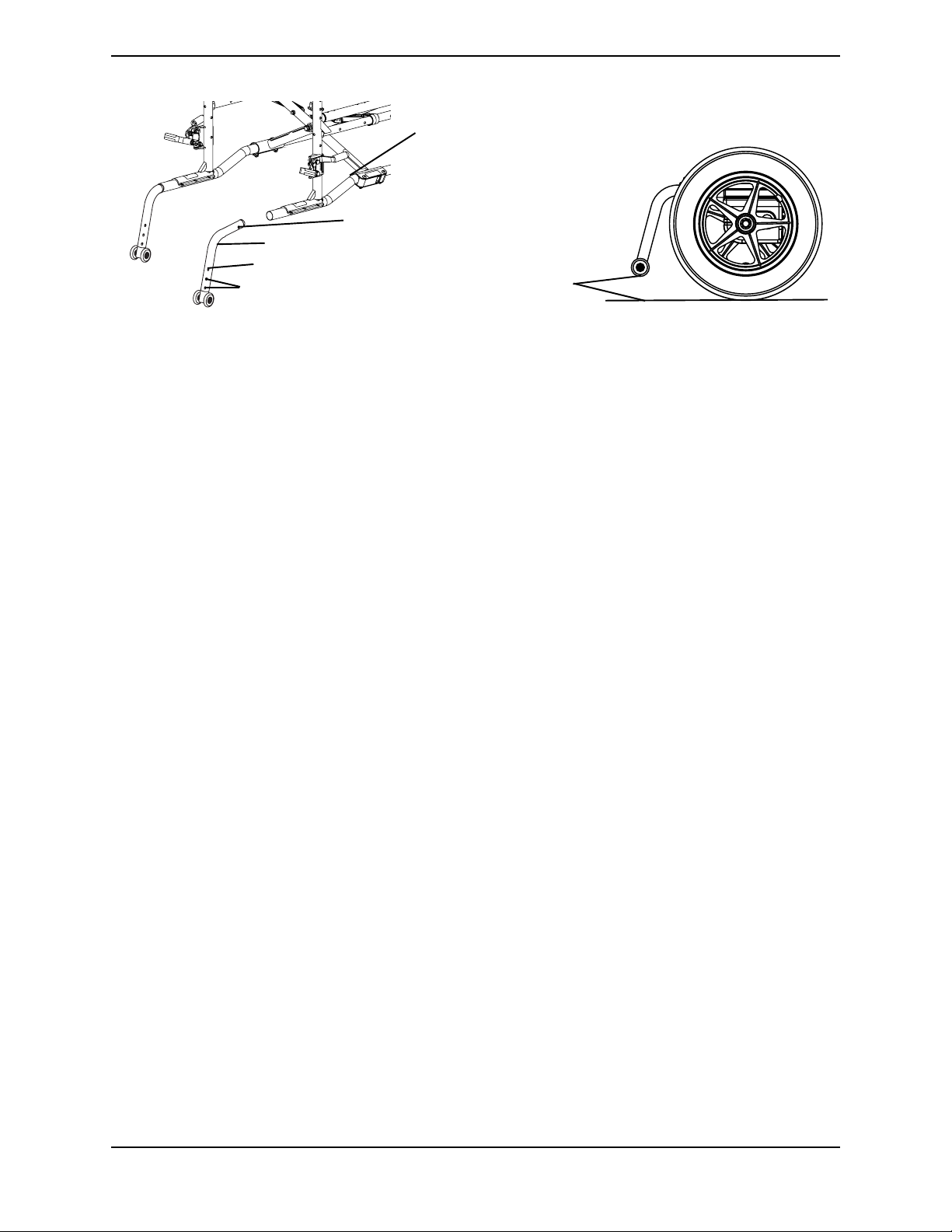
SECTION 14—ANTI-TIPPERS
Wheelchair Frame
Release Button
Anti-tipper
Release Button
Anti-tipper Adjustment Holes
1½ to 2-inch
Clearance
FIGURE 14.1 Installing/Removing/Adjusting Anti-Tippers
Part No. 1118386 65 P9000™ XDT

TRANSPORTING
TRANSPORTING
WARNING
After ANY adjustments, repair or service and BEFORE use, make sure all attaching
hardware is tightened securely - otherwise injury or damage may result.
Transporting the P9000 XDT
WARNING
The weight of the wheelchair without the user and batteries is approximately 82 lbs.
Use proper lifting techniques (lift with your legs) to avoid injury. Extreme caution is
advised when it is necessary to move an unoccupied power wheelchair. Invacare
recommends using two (2) assistants and making thorough preparations. Make sure
to use ONLY secure, non-detachable parts for hand-hold supports.
NOTE: For this procedure, refer to FIGURE 15.1.
Unfolding/Folding the Wheelchair
WARNING
Keep hands and fingers clear of moving parts to avoid injury.
DO NOT place hand or fingers on the underside of the seat rail when opening or
closing the wheelchair.
DO NOT sit or transfer into the wheelchair unless it is fully open and the seat rails
are fully seated into the side frame H-blocks.
Unfolding
1. Push down on the seat rails until the seat rails are positioned in the seat guides.
2. Assemble the wheelchair by following the instructions in this manual.
Folding
1. Remove the anti-tippers. Refer to Installing/Removing/Adjusting Anti-Tippers
page 64.
on
1. Remove the batteries. Refer to Removing/Installing the Battery Boxes on page 50.
2. Remove the footrests/legrests from the wheelchair. Refer to
Installing/Removing/Using the Footrest/Legrest on page 34.
3. Remove the battery tray from the wheelchair. Refer to Installing/Removing Battery
Tray on page 51.
4. Lift up on the seat rails of the wheelchair.
P9000™ XDT 66 Part No. 1118386
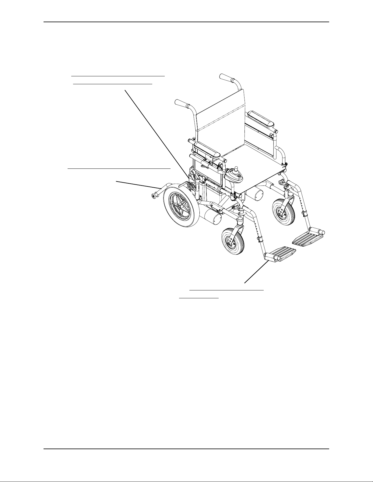
Refer to Removing/Installing the Battery Boxes on page 50
and Installing/Removing Battery Tray
on page 51.
TRANSPORTING
Refer to Installing/Removing/Adjusting Anti-Tippers
on page 64.
FIGURE 15.1 Transporting the P9000 XDT
Refer to Installing/Removing/Using the
Footrest/Legrest on page 34.
Part No. 1118386 67 P9000™ XDT

LIMITED WARRANTY
PLEASE NOTE: THE WARRANTY BELOW HAS BEEN DRAFTED TO COMPLY WITH FEDERAL LAW
APPLICABLE TO PRODUCTS MANUFACTURED AFTER JULY 4, 1975.
This warranty is extended only to the original purchaser/user of our products.
This warranty gives you specific legal rights and you may also have other legal rights which vary from state
to state.
With regards to the original purchaser/user only, Invacare warrants the front and rear frames to be free
from defects in materials and workmanship for a period of three (3) years from date of purchase; seat
frame for a period of three (3) years from the date of purchase; electronics, motors and gearboxes for a
period of one (1) year from the date of purchase; all remaining components for one (1) year from the date
of purchase except upholstered materials, padded materials and tires/wheels. If within such warranty
period any product shall be proven to be defective, such product shall be repaired or replaced, at
Invacare's option. This warranty does not include any labor or shipping charges incurred in replacement
part installation or repair of any such product. Invacare's sole obligation and your exclusive remedy under
this warranty shall be limited to such repair and/or replacement.
For warranty service, please contact the dealer from whom you purchased your Invacare product. In the
event you do not receive satisfactory warranty service, please write directly to Invacare at the address on
the bottom of the back cover. Provide dealer's name address, date of purchase, indicate nature of the
defect and, if the product is serialized, indicate the serial number. Do not return products to our factory
without our prior consent.
LIMITATIONS AND EXCLUSIONS: THE FOREGOING WARRANTY SHALL NOT APPLY TO SERIAL
NUMBERED PRODUCTS IF THE SERIAL NUMBER HAS BEEN REMOVED OR DEFACED, PRODUCTS
SUBJECT TO NEGLIGENCE, ACCIDENT, IMPROPER OPERATION, MAINTENANCE OR STORAGE,
COMMERCIAL OR INSTITUTIONAL USE, PRODUCTS MODIFIED WITHOUT INVACARE'S EXPRESS
WRITTEN CONSENT INCLUDING, BUT NOT LIMITED TO, MODIFICATION THROUGH THE USE
OF UNAUTHORIZED PARTS OR ATTACHMENTS; PRODUCTS DAMAGED BY REASON OF
REPAIRS MADE TO ANY COMPONENT WITHOUT THE SPECIFIC CONSENT OF INVACARE, OR
TO A PRODUCT DAMAGED BY CIRCUMSTANCES BEYOND INVACARE'S CONTROL, AND SUCH
EVALUATION WILL BE SOLELY DETERMINED BY INVACARE. THE WARRANTY SHALL NOT
APPLY TO PROBLEMS ARISING FROM NORMAL WEAR OR FAILURE TO ADHERE TO THESE
INSTRUCTIONS. A CHANGE IN OPERATING NOISE, PARTICULARLY RELATIVE TO MOTORS AND
GEARBOXES DOES NOT CONSTITUTE A FAILURE. ALL SUCH DEVICES WILL EXHIBIT A
CHANGE IN OPERATING NOISE DUE TO AGING.
THE FOREGOING EXPRESS WARRANTY IS EXCLUSIVE AND IN LIEU OF ANY OTHER
WARRANTIES WHATSOEVER, WHETHER EXPRESS OR IMPLIED, INCLUDING THE IMPLIED
WARRANTIES OF MERCHANTABILITY AND FITNESS FOR A PARTICULAR PURPOSE, AND THE
SOLE REMEDY FOR VIOLATIONS OF ANY WARRANTY WHATSOEVER, SHALL BE LIMITED TO
REPAIR OR REPLACEMENT OF THE DEFECTIVE PRODUCT PURSUANT TO THE TERMS
CONTAINED HEREIN, THE APPLICATION OF ANY IMPLIED WARRANTY WHATSOEVER SHALL
NOT EXTEND BEYOND THE DURATION OF THE EXPRESS WARRANTY PROVIDED HEREIN.
INVACARE SHALL NOT BE LIABLE FOR ANY CONSEQUENTIAL OR INCIDENTAL DAMAGES
WHATSOEVER.
THIS WARRANTY SHALL BE EXTENDED TO COMPLY WITH STATE/PROVINCIAL LAWS AND
REQUIREMENTS.
Invacare Corporation
USA
One Invacare Way
Elyria, Ohio USA
44036-2125
800-333-6900
www.invacare.com
Canada
570 Matheson Blvd E Unit 8
Mississauga Ontario
L4Z 4G4 Canada
800-668-5324
Invacare is a registered trademark of
Invacare Corporation.
Yes, you can., P9000 and SPJ are
trademarks of Invacare Corporation
© 2004 Invacare Corporation
Part No. 1118386
Rev B - 10/04
 Loading...