

Page 1

Solara Contracture Footplate Retro Fit Kit
Assembly, Installation and Operating Instructions
Kit Nos. 1095340, 1095341, 1095342, 1095343, 1095344, 1095345, 1095346
SAVE THESE INSTRUCTIONS
NOTE: Check all parts for shipping damage. In case of
damage, DO NOT use. Contact Carrier/Invacare for further instructions.
3. Remove the back canes. Refer to
4. Remove the allen screw, spacer and locknut that
SAFETY SUMMARY
The following recommendations are made for the safe
and proper installation and use of the Contracture
Footplate Retro Fit Kit:
GENERAL WARNINGS
DO NOT install this equipment without first reading and understanding this instruction sheet. If you
are unable to understand the W arnings, Cautions
and Instructions, contact a healthcare professional, dealer or technical personnel if applicable,
before attempting to install this equipment - otherwise, injury or damage may occur.
INST ALLATION WARNINGS
After ANY adjustments, repair or service and BEFORE use, make sure that all attaching hardware
is tightened securely.
This kit contains the following:
DESCRIPTION QTY
Contracture Assembly (Right Side) 1
Contracture Assembly (Left Side) 1
Insert Tube (Crossmember Assembly) 1
Outer Tube (Crossmember Assembly) 1
5. Remove the shoulder screw and locknut securing
6. Repeat STEPS 4-5 for opposite side of seat frame.
7. Lift up to remove the seat frame from the base frame.
NOTE: When reassembling the seat frame, the front
crossbrace will be replaced with the crossmember assembly (insert tube and outer tube) provided in this kit
and will be secured with the EXISTING mounting screws.
NOTE: Right and left sides of the seat frame are determined by sitting in the wheelchair.
8. On the left hand side of the seat frame, remove the
9. Pull the left hand side of the seat frame away from
10. Remove the EXISTING mounting screw, and locknut
INSTALLING THE CONTRACTURE
FOOTPLATE ASSEMBLY
Installing the Crossmember Assembly
(FIGURE 1)
NOTE: Refer to the GENERAL WARNINGS and INSTALLATION WARNINGS in the
instruction sheet.
NOTE: Invacare recommends that two (2) people perform this procedure.
SAFETY SUMMARY of this
11. Remove the front crossbrace from the brace support
12. Insert one end of the insert tube into the front right
13. Align mounting holes in the end of the insert tube with
14. Slide the outer tube over the insert tube as shown in
REMOVING/INSTALLING THE BACK CANES in PROCEDURE 5
of the Service Manual, part number 1085787.
secure the link bracket to the lower seat frame as
shown in DETAIL “A” of FIGURE 1.
the rear of the seat frame to the bearing housing as
shown in DETAIL “A” of FIGURE 1.
two (2) EXISTING mounting screws and locknuts that
secure the front and rear crossbraces to the brace
supports of the seat frame as shown in DETAIL “B”
of FIGURE 1.
the front and rear crossmembers.
that secures the other end of the front crossbrace to
the front right hand side brace support of the seat
frame as shown in DETAIL “B” of FIGURE 1.
and discard.
hand side brace support.
the brace support and secure with the EXISTING
mounting screw and locknut.
DETAIL “B” of FIGURE 1.
NOTE: Take note of position and orientation of the mounting hardware for reassembly.
1. If necessary, remove the seating system from the
wheelchair. Refer to the seating systems Owner’s
Manual supplied with the wheelchair.
2. Remove the seat pan. Refer to
STALLING THE SEAT PAN in PROCEDURE 4 of
the Service Manual, part number 1085787.
REMOVING/IN-
15. Align the brace supports of the left hand side of the
seat frame with the front and rear crossmembers.
16. Insert the front and rear crossmembers into the brace
supports of the left hand side of the seat frame. Reinstall
the two (2) EXISTING mounting screws and locknuts.
1
Page 2
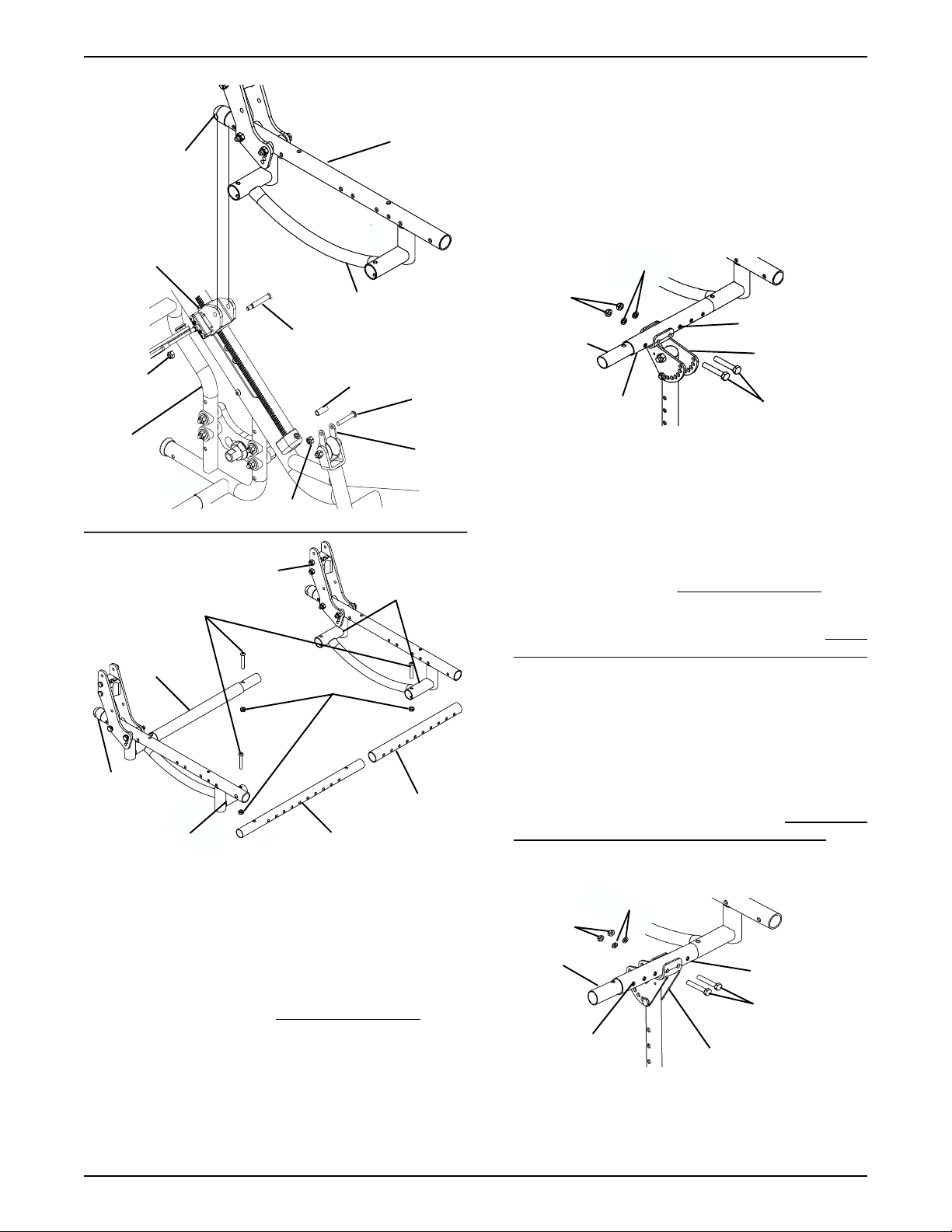
Seat Frame
(Rear)
DETAIL “A”
Seat Frame
2. Align the mounting holes of the contracture footplate
assembly with two (2) desired mounting positions of
the crossmember assembly.
3. Secure the contracture assembly to the crossmember
assembly with two (2) mounting screws, washers and
locknuts provided. Securely tighten.
4. If necessary, repeat STEPS 1-6 for the other contracture assembly.
Bearing
Housing
Lower Seat Frame
Shoulder Screw
Locknut
Base
Frame
DETAIL “B”
Crossbrace
(Rear)
Seat
Frame
Brace Support
Locknut
Seat Frame
Mounting Screws
Lock Nuts
Spacer
Allen
Screw
Link
Bracket
Brace Support
Outer Tube
Insert Tube
FIGURE 1 - INST ALLING THE CROSSMEMBER
ASSEMBL Y
Installing the Contracture Assembly - Forward
Mount (FIGURE 2)
NOTE: Refer to the GENERAL WARNINGS and INSTALLATION WARNINGS in the
instruction sheet.
NOTE: The number of mounting positions on the contracture assembly may vary due to the width of the wheelchair.
1. Align the mounting holes of the outer tube with the
mounting holes of the insert tube of the crossmember
assembly.
SAFETY SUMMARY of this
Washers
Lock Nuts
Mounting Holes
Insert Tube
Outer Tube
Contracture
Assembly
Mounting Screws
FIGURE 2 - REMOVING/INST ALLING THE
CONTRACTURE ASSEMBLY - FORWARD MOUNT
Installing the Contracture Assembly Reversed Mount (FIGURE 3)
NOTE: Refer to the GENERAL WARNINGS and INSTALLATION WARNINGS in the
instruction sheet.
1. Remove the contracture footplate. Refer to CONTRACTURE FOOTPLATE HEIGHT ADJUSTMENT
in this instruction sheet.
2. Align the mounting holes of the contracture footplate
assembly with two (2) desired mounting positions of
the crossmember assembly.
3. Secure the contracture assembly to the crossmember
assembly with two (2) mounting screws, washers and
locknuts provided. Securely tighten.
4. Reinstall the contracture footplate. Refer to
TURE FOOTPLATE HEIGHT ADJUSTMENT.
5. If necessary, repeat STEPS 1-4 for the other contracture assembly.
Washers
Lock Nuts
Insert
Tube
Mounting
Holes
SAFETY SUMMARY of this
CONTRAC-
Outer Tube
Mounting
Screws
Contracture Assembly
FIGURE 3 - REMOVING/INST ALLING THE
CONTRACTURE ASSEMBLY - REVERSED MOUNT
2
Page 3

CONTRACTURE ASSEMBLY ANGLE
ADJUSTMENT (FIGURE 4)
NOTE: Refer to the GENERAL WARNINGS and INSTALLATION WARNINGS in the SAFETY SUMMARY of this
instruction sheet.
Angle Adjustment
Bracket
Pop Rivet
1. Remove the mounting screw and locknut used to lock
the angle adjustment of the contracture assembly.
2. Lift the contracture support UP/DOWN to achieve
the desired angle.
3. Align the mounting hole in the contracture support
with one (1) of seven (7) mounting holes on the angle
adjustment bracket.
4. Reinstall the mounting screw and locknut used to lock
the angle adjustment of the contracture assembly.
Securely tighten.
5. If necessary repeat STEPS 1-4 on remaining contracture assembly.
Mounting Screw
Angle
Adjustment
Bracket
Mounting
Hole
Locknut
Contracture Support
FIGURE 4- CONTRACTURE ASSEMBLY ANGLE
ADJUSTMENT
USING THE OPTIONAL QUICK
RELEASE PIN (FIGURE 5)
NOTE: Refer to the GENERAL WARNINGS and INSTALLATION WARNINGS in the
instruction sheet.
SAFETY SUMMARY of this
Button
Quick Release Pin
Contracture
Support
FIGURE 5 - USING THE OPTIONAL QUICK
RELEASE PIN
ANGLE ADJUSTMENT OF THE
CONTRACTURE FOOTPLATE
(FIGURE 6)
NOTE: Refer to the GENERAL WARNINGS and INSTALLATION WARNINGS in the
instruction sheet.
1. Loosen, but DO NOT, remove the two (2) flat screws,
washers and locknuts that secure contracture
footplate to the footplate hinge.
2. Tilt the contracture footplate UP/DOWN to achieve
desired angle.
3. Retighten the two (2) flat screws, washers and locknuts that secures the contracture foot plate to the
footplate hinge.
4. If necessary repeat STEPS 1-3 on remaining contracture footplate.
Contracture
Assembly
SAFETY SUMMARY of this
Flat Screws
Contracture
Footplate
NOTE: The Quick Release Pin replaces the mounting
screw that is used to lock the angle adjustment of the
contracture support.
NOTE: If not installed at time of shipment, the quick release
pin must be installed by a qualified technician only, using a
1/8-inch pop rivet.
1. Press the button on the quick release pin and insert
through the contracture support and the angle adjustment bracket.
2. If necessary adjust the angle of the contracture assembly. Refer to CONTRACTURE ASSEMBLY
ANGLE ADJUSTMENT in this instruction sheet.
3. Repeat STEPS 1-2 on the remaining contracture assembly.
Footplate
Hinge
NOTE: Mounting hardware
shown removed for clarity
only.
FIGURE 6 - ANGLE ADJUSTMENT OF THE
CONTRACTURE FOOTPLATE
3
Washers
Lock Nuts
Page 4

CONTRACTURE FOOTPLATE
DEPTH ADJUSTMENT (FIGURE 7)
NOTE: Refer to the GENERAL WARNINGS and INSTALLATION WARNINGS in the
SAFETY SUMMARY of this
instruction sheet.
NOTE: Observe the angle of the contracture footplate for
reinstallation.
1. Remove the two (2) flat screws, washers and locknuts that secure the contracture footplate to the
footplate hinge.
2. Move the contracture footplate to one (1) of four (4)
mounting hole.
3. Reinstall the two (2) flat screws, washers and locknuts that secures the contracture foot plate to the
footplate hinge.
Flat Screws
Mounting
Hole
Contracture
Footplate
Washers
Footplate Hinge
Lock Nuts
FIGURE 7 - CONTRACTURE FOOTPLATE DEPTH
ADJUSTMENT
CONTRACTURE FOOTPLATE
HEIGHT ADJUSTMENT (FIGURE 8)
NOTE: Refer to the GENERAL WARNINGS and INSTALLATION WARNINGS in the
instruction sheet.
SAFETY SUMMARY of this
4. Secure the footplate bracket to the contracture support with the mounting screw, two (2) coved washers,
washer and locknut. Securely tighten.
5. If necessary repeat STEPS 1-4 on remaining contracture footplate.
Mounting
Contracture Support
Holes
Mounting Screws
Lock Nut
Coved Washers
Washers
Footplate
Bracket
FIGURE 8 - CONTRACTURE FOOTPLATE HEIGHT
ADJUSTMENT
REPLACING THE CONTRACTURE
FOOTPLATE HEEL LOOP (FIGURE 9)
NOTE: Refer to the GENERAL WARNINGS and INSTALLATION WARNINGS in the
instruction sheet.
1. Tilt the contracture footplate forward to gain access to the
mounting screws that secure the heel loop to the underside of the contracture foootplate. Refer to angle adjustment of the contracture footplate in this instruction sheet.
2. Remove the four (4) mounting screws and washers
that secure the EXISTING heel loop to the contracture footplate.
3. Reverse STEPS 1-2 to install the NEW heel loop.
Mounting
Screws
SAFETY SUMMARY of this
Washers
Contracture
Footplate
1. Remove the mounting screw, two (2) coved washer,
washer and locknut that secure the footplate bracket
to the contracture support.
2. Move the footplate bracket UP/DOWN to achieve
desired height.
3. Align the mounting hole in the footplate bracket with
one (1) of seven (7) mounting holes on the contracture support.
Invacare Corporation www.invacare.com
USA Canada
One Invacare Way 5970 Chedworth Way Invacare and "Yes, you can" are trademarks of Invacare
Elyria, Ohio USA Mississauga, Ontario Corporation.
44036-2125 L5R 3T9, Canada © 2000 Invacare Corporation
800-333-6900 905-890-8838 Form No. 00-97 Part No. 1095349 Rev A (1) 5/00
Washers
Heel Loop
FIGURE 9 - REPLACING THE CONTRACTURE
FOOTPLATE HEEL LOOP
 Loading...