

Space Saver / Conventional Arm Socket Assemblies
Assembly, Installation and Operating Instructions
Kit Numbers 1036793, 1036794, 1094952, 1094953
SAVE THESE INSTRUCTIONS
NOTE: Check all parts for shipping damage before using. In case of damage, DO NOT use the equipment.
Contact the Dealer/Carrier for further instructions.
SAFETY SUMMARY
The following recommendations are made for the
safe use of the Space Saver/ Conventional Arm
Socket Assemblies:
GENERAL WARNING
DO NOT install or use this equipment without first reading and understanding these
instructions. If you are unable to understand the Warnings, Cautions or Instructions, contact a healthcare professional,
dealer or technical personnel before attempting to install this equipment - otherwise, injury or damage may occur.
INSTALLATION WARNING
After ANY adjustments, repair or service
and BEFORE use, make sure that all attaching hardware is tightened securely.
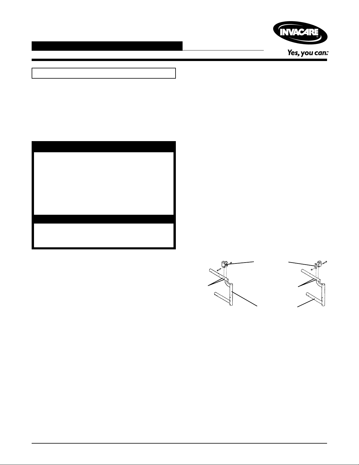
FRONT ARMREST SOCKET
REPLACEMENT/H-BLOCK
INSTALLATION (FIGURE 1)
1. Remove the locknut and screw securing the H-block
to the right and left front frames (FIGURE 1).
2. Remove the H-blocks.
NOTE: It may be necessary to reposition the wheel lock
assembly before/after installing the new front armrest sockets/H-Blocks.
3. Position the NEW armrest socket/H-Block onto the
right and left front frames by performing one (1) of the
following:
NOTE: Armrest sockets/H-Block MUST be positioned
in the 1st or 2nd mounting hole on the right and left front
frames depending on the type of wheelchair.
A. MVP/STYLE 14 through 16 inches deep - Align
the mounting hole in the H-block with the first
mounting hole on front of chair.
B. ALL type wheelchairs 17 and 18-inch deep - Align
the mounting hole on the H-block with the second
mounting hole on front of chair.
PURPOSE
To replace existing half-arms or install new FIXED or ADJUSTABLE arms on Invacare MVP and STYLE wheelchairs built after 10-10-92.
The Invacare MVP or STYLE can be fitted with Space
Saver or Conventional mounting brackets with either fixed
oradjustable arms. These arms can be used on all chairs
14 through 18 inches.
Armrest Socket/
H-Blocks
Mounting
Holes
Mounting
Holes
Front Frames
FIGURE 1 - FRONT ARMREST SOCKET
REPLACEMANT/H-BLOCK INSTALLATION
1
REAR ARMREST SOCKET
INSTALLATION ON WHEELCHAIRS
BUILT BEFORE 7/00
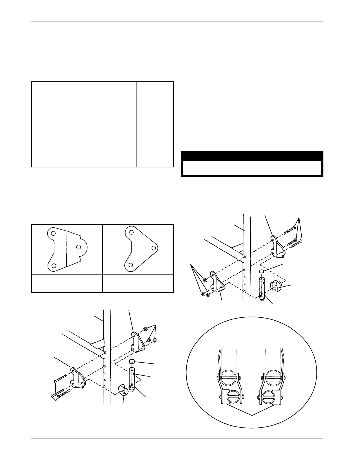
Space Saver Armrest Sockets (FIGURE 2)
Space Saver Kit No. 1036793 Includes the following:
DESCRIPTION QTY.
Left Outside Armrest Bracket 1
Left Inside Armrest Bracket 1
Left Armrest Spacer 1
Right Outside Armrest Bracket 1
Right Inside Armrest Bracket 1
Right Armrest Spacer 1
Front Armrest Socket 2
Rear Armrest Socket 2
Tube Supports 2
Hex Screw 8
Locknuts 8
1. Insert the tube support into armrest socket.
NOTE: Tube support MUST be positioned below mounting hole.
3. Position the armrest spacer flush against the inside
of the outside armrest bracket as shown in “DETAIL
A”, FIGURE 2.
4. Place the armrest socket into the groove of the armrest spacer.
5. Position inside armrest bracket against the armrest
socket (FIGURE 2).
6. Loosely secure the brackets, armrest socket and armrest spacer together using one (1) of the six (6) hex
screws and a locknut.
7. Position the armrest bracket on the rear frame making
sure that the armrest spacer is positioned on the outside
of the rear armrest socket. Refer to Detail “A” in FIGURE 2.
8. Secure the assembly of the chair frame using two (2) of
the six (6) hex screws and locknuts.
CAUTION
Make sure that all screws and locknuts
are secure at all times.
9. Repeat this procedure for the opposite side of the chair
frame.
2. Position the outside armrest bracket towards the outside of the chair frame.
Outside
Armrest Bracket
Inside
Armrest Bracket
Left Inside
Armrest Bracket
Left Chair Frame
Locknuts
Left Outside
Armrest Bracket
Tube
Support
Right Chair
Frame
Locknuts
Right Inside
Armrest Bracket
OUTSIDE
Right Outside
Armrest Bracket
DETAIL “A”
TOP VIEWS
Left
INSIDE
Hex Screw
Tube Support
Armrest
Spacer
Rear Armrest
Socket
Right
OUTSIDE
Mounting
Hole
Hex Screws
Armrest
Rear Armrest
Socket
Spacer
Armrest Spacers
FIGURE 2 - REAR ARMREST SOCKET INSTALLATION - SPACE SAVER ARMS
2
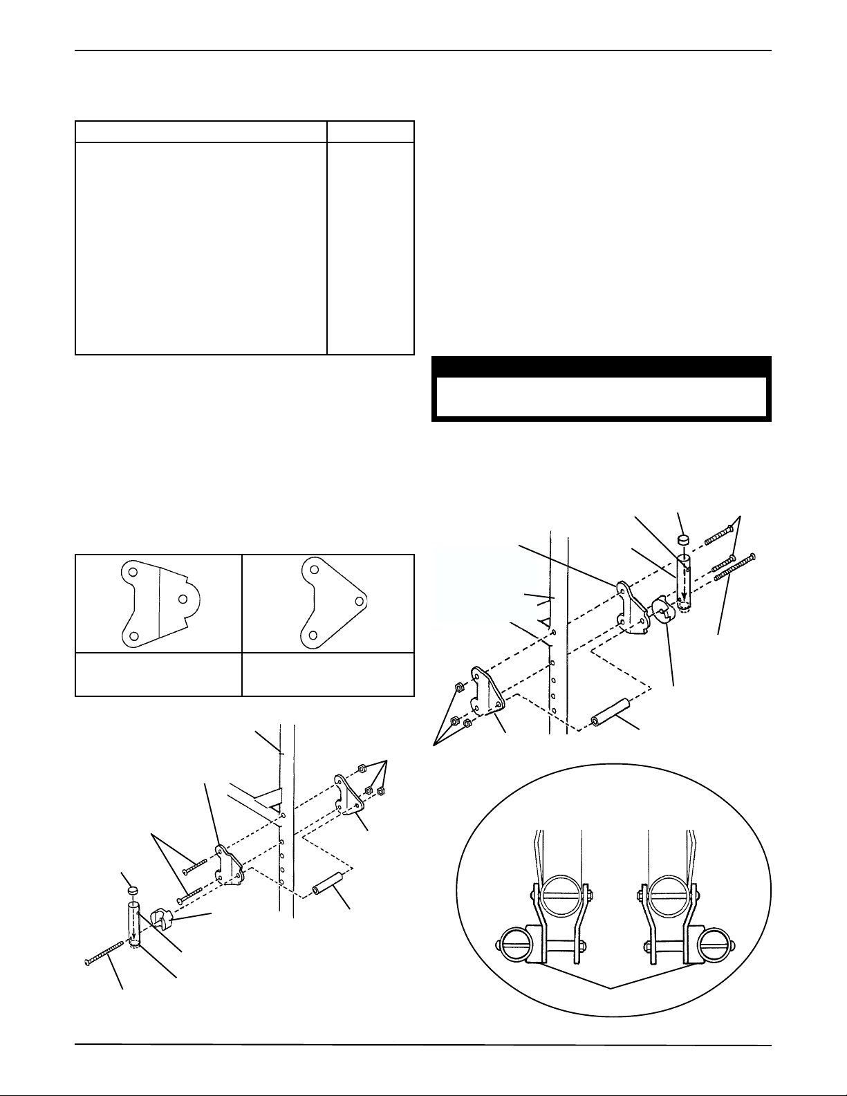
Conventional Armrest Sockets (FIGURE 3)
Conventional Kit No. 1036794 includes the following:
DESCRIPTION QTY.
Left Outside Armrest Bracket 1
Left Inside Armrest Bracket 1
Left Armrest Spacer 1
Right Outside Armrest Bracket 1
Right Inside Armrest Bracket 1
Right Armrest Spacer 1
Front Armrest Socket 2
Rear Armrest Socket 2
Tube Supports 2
Spacer 2
Long Hex Screw 2
Short Hex Screw 6
Locknuts 8
4. Place the armrest socket into the groove of the armrest spacer.
5. Position the bracket spacer flush against the inside of
the outside armrest bracket.
6. Position inside armrest bracket against the bracket spacer.
7. Loosely secure the brackets, armrest socket, armrest
spacer and bracket spacer together using one (1) of
the two (2) long hex screws and a locknut.
8. Position the armrest bracket on the rear frame making
sure that the armrest spacer is positioned on the outside
of the rear armrest socket. Refer to DETAIL “A” in
FIGURE 1.
9. Secure the assembly of the chair frame using two (2) of
the four (4) short hex screws and locknuts.
1. Insert the tube support into armrest socket.
NOTE: Tube support MUST be positioned below mounting hole.
2. Position the outside armrest bracket towards the outside
of the chair frame.
3. Position the armrest spacer flush against the outside
of the outside armrest bracket as shown in “DETAIL
A”, FIGURE 3.
Outside
Armrest Bracket
Inside
Armrest Bracket
Left Chair Frame
Left Outside
Locknuts
Armrest Bracket
Short
Hex Screws
Left Inside
Armrest Bracket
Tube Support
CAUTION
Make sure that all screws and locknuts
are secure at all times.
10. Repeat this procedure for the opposite side of the chair
frame.
Right Outside
Armrest
Bracket
Mounting Hole
Rear
Armrest
Socket
Tube
Support
Short Hex
Screw
Right Chair
Frame
Long Hex
Screw
Armrest
Spacer
Right Inside
Armrest Bracket
Bracket
Spacer
DETAIL “B”
TOP VIEW
Left
INSIDE
OUTSIDE
Right
OUTSIDE
Armrest
Spacer
Bracket
Spacer
Mounting Hole
Rear Armrest Socket
Long Hex Screw
Armrest Spacers
FIGURE 3 - REAR ARMREST SOCKET INSTALLATION - CONVENTIONAL ARMS
3

REAR ARMREST SOCKET
INSTALLATION ON WHEELCHAIRS
BUILT AFTER 7/00
Space Saver Armrest Sockets (FIGURE 4)
Space Saver Kit No. 1094952 includes the following:
DESCRIPTION QTY.
Armrest Brackets 2
Front Armrest Sockets 2
Rear Armrest Sockets 2
Tube Supports 2
Nylon Washers 4
Long Hex Screw 2
Short Hex Screw 6
Locknuts 6
Hex Locknut 2
1. Position armrest bracket into mounting position. Refer to Owner’s Manual, supplied with the wheelchair,
for proper mounting positions.
2. Install armrest bracket onto wheelchair frame and
secure using short hex screw and locknut. Securely
tighten.
3. Insert the tube support into the armrest socket ensuring that the holes in the tube support align with the
holes in the armrest socket.
4. Install the armrest socket into the armrest bracket.
NOTE: Mounting hardware must be installed in the
oreintation shown in FIGURE 4.
5. Install short hex screw through armrest bracket,
washer, armrest socket, tube support, washer and
armrest bracket as shown in FIGURE 4.
6. Secure with locknut.
7. Install remaining short hex screw (used as armrest
stop) through armrest bracket and secure with locknut.
8. Repeat this procedure for the opposite side of the chair
frame.
MOUNTING HOLES
Armrest
Socket
Armrest Stop
Armrest Bracket
Tube Support
Armrest
Socket
Washer
Armrest
Bracket
Tube Support
Armrest
Socket
Washer
Armrest
Bracket
Locknut
Short Hex
Screw
Wheelchair
Frame
Short Hex
Screw
FIGURE 4 - REAR ARMREST SOCKET INSTALLATION ON WHEELCHAIRS BUILT
AFTER 7/00 - SPACE SAVER ARMREST SOCKETS
4

Conventional Armrest Sockets (FIGURE 5)
Conventional Kit No. 1094953 includes the following:
DESCRIPTION QTY.
Armrest Bracket 2
Bracket Spacer 2
Front Armrest Socket 2
Rear Armrest Socket 2
Coved Armrest Spacer 2
Tube Supports 2
Nylon Washers 2
Long Hex Screw 2
Medium Hex Screw 2
Short Hex Screw 2
Locknuts 4
Hex Locknut 2
DETAIL “A” - TOP VIEW
Tube
Support
LEFT
Wheelchair
Frame
Spacer
RIGHT
Armrest
Socket
Hex
Screw
1. Position armrest bracket into mounting position. Refer to Owner’s Manual for proper mounting positions.
2. Install armrest bracket onto wheelchair frame and
secure using short hex screw and locknut.
3. Insert the tube support into the armrest socket ensuring that the holes in the tube support align with the
holes in the armrest socket.
4. Install the armrest socket into the armrest bracket.
NOTE: Mounting hardware must be installed in the
oreintation shown in FIGURE 5.
5. Install long hex screw through armrest socket, tube
support, coved armrest spacer, washer, armrest
bracket, spacer and armrest bracket as shown in DETAIL “A”.
NOTE: Ensure armrest socket is flush in coved spacer.
6. Secure with locknut.
7. Repeat this procedure for the opposite side of the chair
frame.
Coved
Armrest
Spacer
Armrest
Bracket
Coved
Armrest
Spacer
Armrest
Bracket
Spacer
Tube Support
Locknut
Armrest
Socket
Washer
Long
Hex
Screw
Short
Coved
Armrest
Spacer
Hex
Screw
FIGURE 5 - REAR ARMREST SOCKET INSTALLATION ON WHEELCHAIRS BUILT
AFTER 7/00 - CONVENTIONAL ARMREST SOCKETS
Wheelchair
Frame
5

ARMREST OPERATION
CAUTION
After any adjustments, make sure the locking mechanism is secured before using the
wheelchair.
Adjustable Height Armrest (FIGURE 6)
HEIGHT ADJUSTMENT.
1. Unlock the arm by flipping the height adjustment lever
to the UP position.
2. Adjust the arm to the desired height.
3. Lock the arm by pressing the height adjustment lever
into the DOWN position.
REMOVING/INSTALLING.
1. Unlock the arm by rotating both release levers towards
the outside of the chair.
2. Pull arm straight up and out of the socket.
3. Insert the arm straight down and into the socket.
4. Lock the arm by rotating both release levers toward
the inside of the chair.
Swing-Away Armrest (FIGURE 7)
SWINGING AWAY.
1. Unlock the arm by rotating the release lever(s) towards
the outside of the chair.
2. Pull the front of arm straight up/out of the socket and
towards the rear of the chair.
3. To lock, push the arm towards the front of the chair;
then downward and into the socket (unlocked).
4. When the arm is in place turn release lever towards
the inside of the chair.
REMOVING/INSTALLING.
1. Unlock the arm by rotating both release levers towards
the outside of the chair.
2. Pull arm straight up and out of the socket.
3. Insert the arm straight down and into the socket.
4. Lock the arm by rotating both release levers toward
the inside of the chair.
Armrest Release
Lever
Fixed Height Armrest (FIGURE 6)
REMOVING/INSTALLING.
1. Unlock the arm by rotating both release levers towards
the outside of the chair.
2. Pull arm straight up and out of the socket.
3. Insert the arm straight down and into the socket.
4. Lock the arm by rotating both release levers toward
the inside of the chair.
Unlock
(Horizontal)
Lock
(Vertical)
Armrest
Release
Lever
Height Adjust-
ment Lever
Armrest
Release
Lever
FIGURE 6 - ARMREST OPERATION
ADJUSTABLE/FIXED HEIGHT ARMREST
Armrest
Release
Lever
FIGURE 7 - ARMREST OPERATION
SWING-AWAY ARMREST
6

NOTES
7

Invacare Corporation www.invacare.com
USA Canada
One Invacare Way 5970 Chedworth Way Invacare and "Yes, you can" are trademarks of Invacare
Elyria, Ohio USA Mississauga, Ontario Corporation.
44036-2125 L5R 3T9, Canada © 2000 Invacare Corporation
800-333-6900 905-890-8838 Form No. 93-29 Part No. 1040101 Rev B (1)10/00
 Loading...