

Page 1
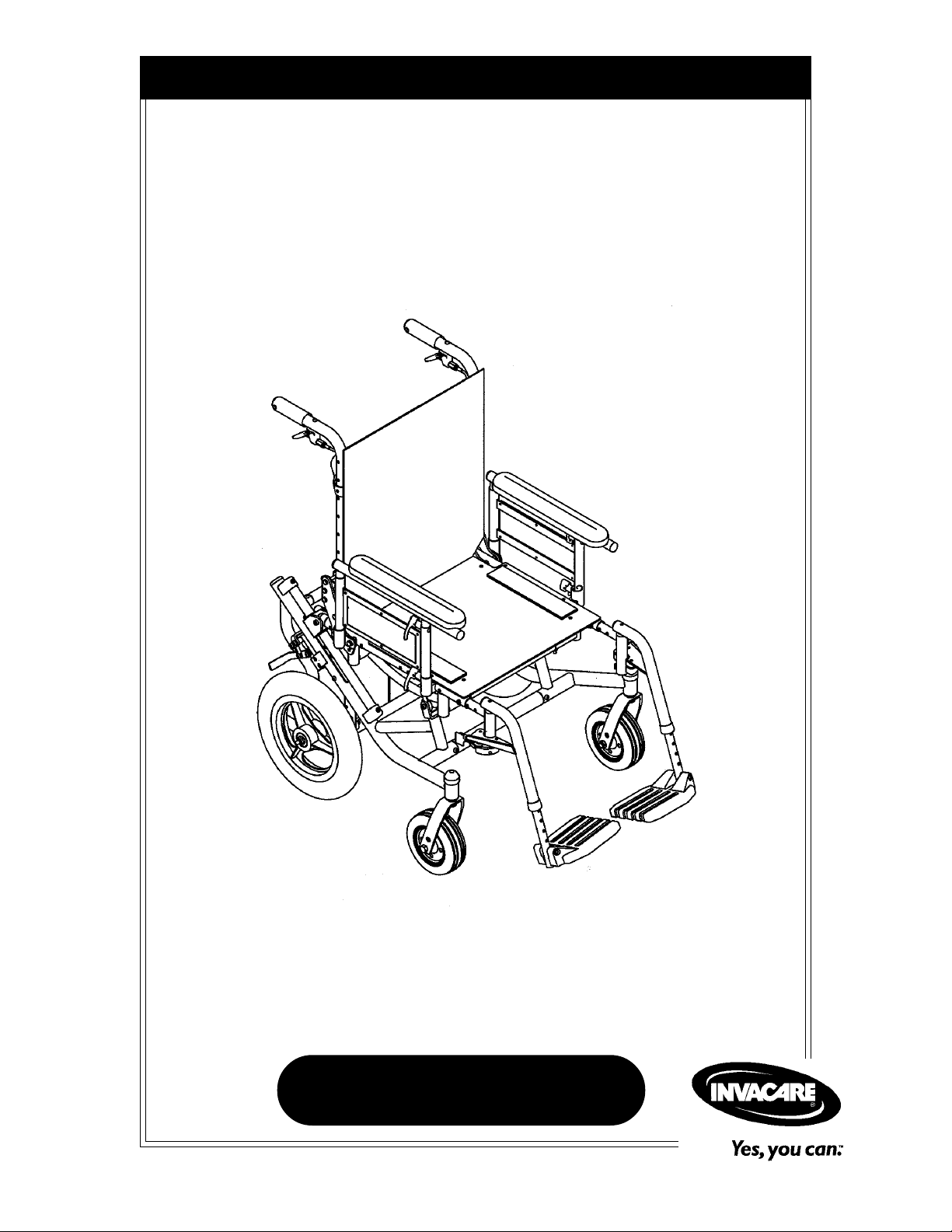
Owner's Operator And Maintenance Manual
™
Solara
Solara™Limited
DEALER: THIS MANUAL MUST BE GIVEN TO THE USER
OF THE WHEELCHAIR.
USER: BEFORE USING THIS WHEELCHAIR, READ THIS
MANUAL AND SAVE FOR FUTURE REFERENCE.
For more information regarding
Invacare products, parts, and services,
please visit: www.invacare.com
Page 2

WARNING
WARNING
WARNING
DO NOT OPERATE THIS EQUIPMENT
WITHOUT FIRST READING AND
UNDERSTANDING THIS MANUAL. IF YOU ARE
UNABLE TO UNDERSTAND THE WARNINGS,
CAUTIONS, AND INSTRUCTIONS, CONTACT
A HEALTHCARE PROFESSIONAL, DEALER OR
TECHNICAL PERSONNEL IF APPLICABLE
BEFORE ATTEMPTING TO USE THIS
EQUIPMENT - OTHERWISE INJURY OR DAMAGE
MAY RESULT.
THE INITIAL SET UP OF THIS WHEELCHAIR
MUST BE PERFORMED BY A QUALIFIED
TECHNICIAN.
PROCEDURES OTHER THAN THOSE DESCRIBED
IN THIS MANUAL
MUST BE PERFORMED BY A
QUALIFIED TECHNICIAN.
Solara™ 2 Part No. 1080556 Rev. I
Page 3

TABLE OF CONTENTS
TABLE OF CONTENTS
SPECIAL NOTES ............................................................................... 5
LABEL LOCATIONS .......................................................................... 6
TABLE OF CONTENTS
SPECIFICATIONSSPECIFICATIONS
SPECIFICATIONS
SPECIFICATIONSSPECIFICATIONS
PROCEDURE 1 - GENERAL GUIDELINESPROCEDURE 1 - GENERAL GUIDELINES
PROCEDURE 1 - GENERAL GUIDELINES
PROCEDURE 1 - GENERAL GUIDELINESPROCEDURE 1 - GENERAL GUIDELINES
INFORMATION FOR HEALTHCARE PROFESSIONALS/ASSISTANTS................................9
STABILITY - ALL MODELS ................................................................................................................. 10
STABILITY - ALL MODELS EXCEPT RECLINERS ..................................................................... 10
STABILITY - RECLINER MODELS ONLY ..................................................................................... 11
OPERATING INFORMATION ......................................................................................................... 11
WEIGHT TRAINING .......................................................................................................................... 12
WEIGHT LIMITATION....................................................................................................................... 12
SAFETY/HANDLING OF WHEELCHAIRS ................................................................................... 13
PROCEDURE 2 - SAFETY INSPECTIONPROCEDURE 2 - SAFETY INSPECTION
PROCEDURE 2 - SAFETY INSPECTION
PROCEDURE 2 - SAFETY INSPECTIONPROCEDURE 2 - SAFETY INSPECTION
SAFETY INSPECTION CHECKLIST............................................................................................... 19
TROUBLESHOOTING ........................................................................................................................ 20
MAINTENANCE ................................................................................................................................... 20
PROCEDURE 3 - TRANSPORTINGPROCEDURE 3 - TRANSPORTING
PROCEDURE 3 - TRANSPORTING
PROCEDURE 3 - TRANSPORTINGPROCEDURE 3 - TRANSPORTING
TRANSPORTING THE INVACARE SOLARA ............................................................................. 21
PROCEDURE 4 - FRONT RIGGINGSPROCEDURE 4 - FRONT RIGGINGS
PROCEDURE 4 - FRONT RIGGINGS
PROCEDURE 4 - FRONT RIGGINGSPROCEDURE 4 - FRONT RIGGINGS
INSTALLING/REMOVING SWINGAWAY FOOTREST .......................................................... 22
ADJUSTING SWINGAWAY FOOTREST HEIGHT .................................................................. 23
ADJUSTING ADJUSTABLE ANGLE FLIP-UP FOOTPLATES ................................................. 24
COMPOSITE/ARTICULATING FOOTPLATE HEEL LOOP REPLACEMENT .................. 25
INSTALLING/REMOVING ELEVATING LEGREST/CALFPAD ASSEMBLY ....................... 25
ADJUSTING THE ELEVATING LEGREST/CALFPAD ASSEMBLY ........................................ 26
..........................................................................................................................................................
.............................................................................
..........................................................................................................................................................
......................................................................................
...........................................
......................................................................................
........................................................................................
............................................
........................................................................................
....................................................................................................
..................................................
....................................................................................................
..................................................................................................
.................................................
..................................................................................................
1919
19
1919
2121
21
2121
2222
22
2222
88
8
88
99
9
99
PROCEDURE 5PROCEDURE 5
PROCEDURE 5 -
PROCEDURE 5PROCEDURE 5
INSTALLING/REMOVING/ADJUSTING DUAL POINT ARMREST ..................................... 27
USING/INSTALLING/ADJUSTING LOCKING CANTILEVER ARMS ................................. 29
USING/INSTALLING/ADJUSTING NON-LOCKING CANTILEVER ARMS .................... 32
ARM PAD REPLACEMENT FOR CANTILEVER ARMS ........................................................... 34
INSTALLING/REMOVING T-ARMS................................................................................................ 34
ADJUSTING THE T-ARMS ................................................................................................................ 35
ADJUSTING T-ARM TRANSFER ASSISTS AND/OR SIDE GUARDS.................................. 37
PROCEDURE 6PROCEDURE 6
PROCEDURE 6 -
PROCEDURE 6PROCEDURE 6
FOLDING/UNFOLDING BACK ASSEMBLY ................................................................................ 38
INSTALLING/REMOVING THE STROLLER HANDLES........................................................... 39
INSTALLING/REMOVING/ADJUSTING THE ADJUSTABLE ANGLE
STROLLER HANDLES.................................................................................................................. 40
INSTALLING/REPLACING SEAT POSITIONING STRAPS .................................................... 42
INSTALLING/REPLACING CHEST POSITIONING STRAPS ................................................ 43
INSTALLING/REPLACING THE BACK UPHOLSTERY........................................................... 43
INSTALLING THE SEAT CUSHION .............................................................................................. 44
Part No. 1080556 Rev. I 3 Solara™
ARMSARMS
ARMS
ARMSARMS
BACK/SEATBACK/SEAT
BACK/SEAT
BACK/SEATBACK/SEAT
......................................................................................................................................
...................................................................
......................................................................................................................................
....................................................................................................................
..........................................................
....................................................................................................................
2727
27
2727
3838
38
3838
Page 4

TABLE OF CONTENTS
PROCEDURE 7 - TILT-IN-SPACEPROCEDURE 7 - TILT-IN-SPACE
PROCEDURE 7 - TILT-IN-SPACE
PROCEDURE 7 - TILT-IN-SPACEPROCEDURE 7 - TILT-IN-SPACE
ENGAGING TILT-IN-SPACE ........................................................................................................... 45
ADJUSTING TRIGGER RELEASE CABLES ................................................................................... 46
POSITIONING TILT LOCKING COLLARS ................................................................................. 47
PROCEDURE 8 - WHEELS/FORKSPROCEDURE 8 - WHEELS/FORKS
PROCEDURE 8 - WHEELS/FORKS
PROCEDURE 8 - WHEELS/FORKSPROCEDURE 8 - WHEELS/FORKS
INSTALLING/REMOVING REAR WHEELS ................................................................................. 49
ADJUSTING THE QUICK-RELEASE AXLE ................................................................................. 50
SEAT-TO-FLOOR HEIGHT ADJUSTMENT ................................................................................. 51
ADJUSTING FORKS ............................................................................................................................ 51
PROCEDURE 9 - WHEEL LOCKS/ANTI-TIPPERSPROCEDURE 9 - WHEEL LOCKS/ANTI-TIPPERS
PROCEDURE 9 - WHEEL LOCKS/ANTI-TIPPERS
PROCEDURE 9 - WHEEL LOCKS/ANTI-TIPPERSPROCEDURE 9 - WHEEL LOCKS/ANTI-TIPPERS
WHEEL LOCK ADJUSTMENT......................................................................................................... 52
TABLE OF CONTENTS
USING THE WHEEL LOCKS ...........................................................................................................53
INSTALLING/ADJUSTING ANTI-TIPPERS .................................................................................. 53
PROCEDURE 10 - RECLINER BACK OPTIONPROCEDURE 10 - RECLINER BACK OPTION
PROCEDURE 10 - RECLINER BACK OPTION
PROCEDURE 10 - RECLINER BACK OPTIONPROCEDURE 10 - RECLINER BACK OPTION
RECLINER OPERATION.................................................................................................................... 55
REPLACING/BACK HEADREST UPHOLSTERY ........................................................................ 57
ADJUSTING THE RECLINER CABLES .......................................................................................... 57
REPLACING THE RECLINER CABLES.......................................................................................... 58
REPLACING THE GAS CYLINDERS.............................................................................................. 60
ADJUSTING THE GAS CYLINDERS .............................................................................................. 62
..........................................................................................................
.....................................................
..........................................................................................................
..........................................................................................................
.....................................................
..........................................................................................................
..............................................................
...............................
..............................................................
......................................................................
...................................
......................................................................
4545
45
4545
4949
49
4949
5252
52
5252
5555
55
5555
PROCEDURE 11 - CONTRACTURE FOOTPLATE OPTION .................. 64
INSTALLING THE CONTRACTURE FOOTPLATE ASSEMBLY ........................................... 64
CONTRACTURE ASSEMBLY ANGLE ADJUSTMENT............................................................. 67
USING THE OPTIONAL QUICK-RELEASE PIN ....................................................................... 67
ANGLE ADJUSTMENT OF THE CONTRACTURE FOOTPLATE....................................... 68
CONTRACTURE FOOTPLATE DEPTH ADJUSTMENT ........................................................ 68
CONTRACTURE FOOTPLATE HEIGHT ADJUSTMENT ...................................................... 69
REPLACING THE CONTRACTURE FOOTPLATE HEEL LOOP ......................................... 70
PROCEDURE 12 - TRANSPORT READY OPTION ............................. 71
COMPLIANCE INFORMATION ..................................................................................................... 72
SECURING THE WHEELCHAIR TO THE VEHICLE ............................................................... 72
SECURING THE OCCUPANT ........................................................................................................ 73
NOTES........................................................................................... 78
LIMITED WARRANTY .................................................................... 79
Solara™ 4 Part No. 1080556 Rev. I
Page 5

SPECIAL NOTES
SPECIAL NOTES
WARNING/CAUTION notices as used in this manual apply to hazards or
unsafe practices which could result in personal injury or property damage.
NOTICE
THE INFORMATION CONTAINED IN THIS DOCUMENT IS SUBJECT TO
CHANGE WITHOUT NOTICE.
As a manufacturer of wheelchairs, Invacare endeavors to supply a wide variety
of wheelchairs to meet many needs of the end user. However, final selection of
the type of wheelchair to be used by an individual rests solely with the user and
his/her healthcare professional capable of making such a selection.
WHEELCHAIR TIE-DOWN RESTRAINTS AND SEAT POSITIONING
STRAPS
Invacare recommends that wheelchair users NOT be transported in vehicles of
any kind while in wheelchairs. As of this date, the Department of
Transportation has not approved any tie-down systems for transportation of a
user while in a wheelchair, in a moving vehicle of any type.
SPECIAL NOTES
It is Invacare’s position that users of wheelchairs should be transferred into
appropriate seating in vehicles for transportation and use be made of the
restraints made available by the auto industry.
AS REGARDS RESTRAINTS - SEAT/CHEST POSITIONING STRAPS - IT IS
THE OBLIGATION OF THE DME DEALER, THERAPISTS AND OTHER
HEALTHCARE PROFESSIONALS TO DETERMINE IF A SEAT/CHEST
POSITIONING STRAP IS REQUIRED TO ENSURE THE SAFE OPERATION
OF THIS EQUIPMENT BY THE USER. SERIOUS INJURY CAN OCCUR IN
THE EVENT OF A FALL FROM A WHEELCHAIR.
Part No. 1080556 Rev. I 5 Solara™
Page 6
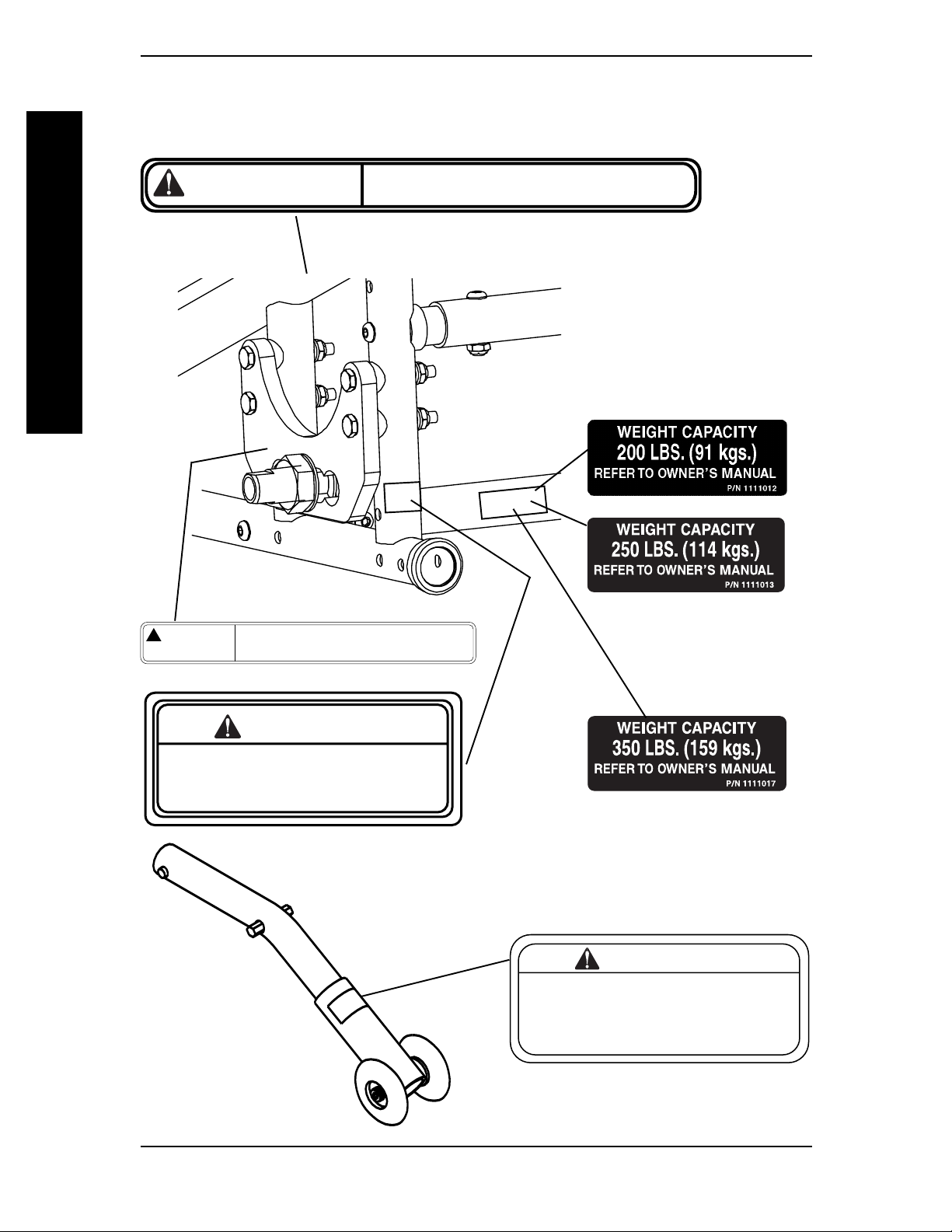
LABEL LOCATIONS
LABEL LOCATIONS
WARNING
LABEL LOCATIONS
Detent balls should extend beyond the diameter of the axle
bushing for a positive lock. Keep detent balls clean.
! WARNING
1085306
DO NOT OPERATE WITHOUT
REV. 5/98
Refer to Owner’s Manual BEFORE
adjusting axle mounting plate.
WARNING
THE ANTI-TIP TUBES
INSTALLED.
P/N 60106X144
HEAVY DUTY
PACKAGE ONLY
WARNING
Refer to Owner's Manual
for proper anti-tipper
setting.
1085379
Solara™ 6 Part No. 1080556 Rev. I
Page 7
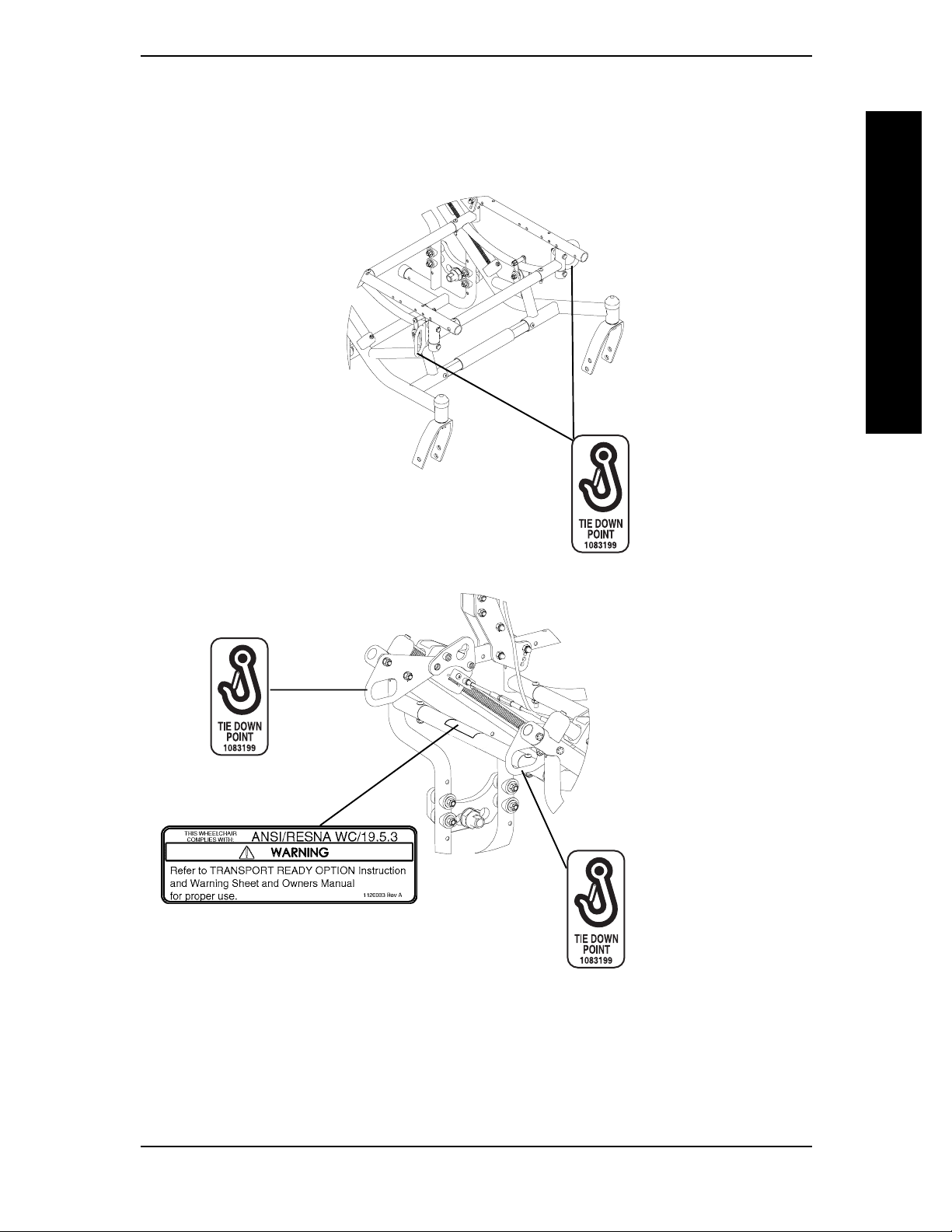
LABEL LOCATIONS
LABEL LOCATIONS
TRANSPORT READY OPTION ONLY
LABEL LOCATIONS
Part No. 1080556 Rev. I 7 Solara™
Page 8

SPECIFICATIONS
Overall Width: Seat Width + 8-1/4-inches (Example: 16-inch Wide Wheelchair =
Overall Depth: W/O Front Riggings
Overall Height: * Seat-to-Floor Height + 21-inches (20-inch back canes)
SPECIFICATIONS
Shipping Weight: 57 lbs.
Anti-Tippers: Standard
Footrest: Swing-Away Footrest (Standard)
Armrests: Dual Point - Adjustable Height
Seat: Optional
Seat Pan Color: Black
Back: Optional
Back Angle Adjustment: 90° to 120°
Rear Axle: Quick-Release
Rear Wheels: 12-inches Pneumatic (Standard); 12-inch Pneumatic w/flat free (Optional);
Handrims: Aluminum Handrims
Caster Size: 6 x 2-inch w/ Precision Sealed Bearings (Standard)
Seat Width: 12 to 22-inches
Seat Depth: Short Frame - 15-17-inches
Back Height: 20 and 24-inches
Wheel Locks: Push-to-Lock (Standard)
Tilt-In-Space: Dual Cable Trigger Mechanism (Standard) - 45° of Tilt
Recliner Back: Dual Cable Trigger Mechanism (Optional) - 0° to 180° of Tilt
Frame: Steel
SPECIFICATIONS
INVACARE SOLARA
SPECIFICATIONS
24-1/4-inches Overall Width)
Short Frame - 29-1/2-inches
Medium Frame - 32-1/2-inches
Long Frame - 34-1/2-inches
* Seat-to-Floor Height + 25-inches (24-inch back canes)
Articulating Swing-Away Footrest (Optional)
Dual Point Fixed Height - Desk Length
Dual Point Fixed Height - Full Length
Locking Cantilever Arms- Desk or Full length
Non-locking Cantilever Arms
Adjustable Height - T-Arms
Fixed
20 and 22-inch Pneumatic, Urethane or Pneumatic w/flat free (Optional)
8-inch w/ Precision Sealed Bearings (Optional)
6 x 1-inch w/ Precision Sealed Bearings (Optional)
Medium Frame - 18-20-inches
Long Frame - 20-22-inches
* NOTE: The seat-to-floor heights are based on pneumatic tires and pneumatic tires with flat free inserts.
If wheelchair is equipped with urethane tires, subtract 1/4-inch from the measurements listed above. All
heights are measured with properly inflated new tires. These heights can vary +1/4-inch due to tire wear.
Solara™ 8 Part No. 1080556 Rev. I
Page 9

This Procedure Includes the Following:
Information For Healthcare Professionals/Assistants
Stability - All Models
Stability - All Models Except Recliners
Stability - Recliner Models ONLY
Operating Information
Weight Training
Weight Limitation
Safety/Handling of Wheelchairs
GENERAL GUIDELINES
INFORMATION FOR HEALTHCARE PROFESSIONALS/
ASSISTANTS
The Solara wheelchair MUST be operated by a healthcare professional or
assistant when in ANY tilt position.
PROCEDURE 1GENERAL GUIDELINES
GENERAL GUIDELINES
WARNING
ANTERIOR (FORWARD) TILT
DO NOT operate the wheelchair when the seat frame is in the anterior
(forward) tilt position (frame stops in the lower position and approximately 10°
forward tilt). Serious bodily injury may occur to the patient and/or the
assistant(s).
Anterior (forward) tilt is a feature of this wheelchair designed for the USE OF
A HEALTHCARE PROFESSIONAL or ASSISTANT ONLY. Engagement of the
anterior (forward) tilt must NEVER be performed by the wheelchair user.
When anterior (forward) tilt is needed, it must ALWAYS be engaged by a
HEALTHCARE PROFESSIONAL or ASSISTANT. Make sure the occupant of
the wheelchair is properly positioned and always engage both wheel locks.
Part No. 1080556 Rev. I 9 Solara™
Page 10

PROCEDURE 1 GENERAL GUIDELINES
STABILITY - ALL MODELS
STABILITY WARNING
The back height, seat depth, back angle, seating system, tilt angle, seat height,
size/position of the rear wheels, size/position of the front casters, as well as the
user condition directly relate to the stability of the wheelchair. Any change to
one (1) or any combination of the eleven (11) may cause the wheelchair to
decrease in stability. These adjustments MUST be performed by a qualified
technician.
GENERAL GUIDELINES
Back Height ● ✓✓✓✓✓✓✓✓N/A N/A N/A N/A
Seat Depth ✓ ● ✓✓N/A ✓✓✓✓N/A N/A N/A ✓
Back Angle ✓✓● ✓✓✓✓✓✓N/A N/A N/A ✓
Seating System ✓✓✓● ✓✓✓✓✓✓N/A N/A N/A
Tilt Angle N/A N/A ✓ N/A ● N/A N/A N/A N/A N/A N/A N/A ✓
Caster Size ✓ N/A ✓ N/A N/A ● ✓✓✓N/A ✓✓✓
Caster Position ✓ N/A ✓ N/A N/A ✓ ● ✓✓N/A ✓✓✓
Wheel Size ✓ N/A ✓ N/A N/A ✓✓● ✓ N/A ✓✓✓
Back Height
Seat Depth
Back Angle
Seating System
Tilt Angle
Caster Size
Caster Position
Wheel Size
Wheel Position
User Condition
Wheel Locks
Anti-Tippers
GENERAL GUIDELINES
Locking Collar
Wheel Position ✓ N/A ✓ N/A N/A ✓✓✓● N/A ✓✓✓
User Condition ✓✓✓✓✓✓✓✓✓● N/A N/A N/A
Seat Height ✓ N/A ✓✓✓✓✓✓✓N/A ✓✓✓
NOTE: When changes to the left hand column occur, follow across the chart and refer to the
✓
procedure to maintain the proper stability, safety and handling of the wheelchair.
ALWAYS make sure that the wheelchair is stable BEFORE using the tilt-inspace.
STABILITY - ALL MODELS EXCEPT RECLINERS
STABILITY WARNINGS
To maintain maximum stability, position the rear wheels in the most rearward
position in the axle mounting plate. Moving the rear wheels to any of the other
mounting positions causes the wheelchair to decrease in stability.
If moving the rear wheels to ANY forward position, ensure the wheelchair is
stable BEFORE using.
ALWAYS ensure stability BEFORE using maximum amount of tilt-in-space or
moving the rear wheels forward. TEST wheelchair BEFORE it is occupied by
the end user to ensure safety.
Solara™ 10 Part No. 1080556 Rev. I
Page 11

GENERAL GUIDELINES
STABILITY - RECLINER MODELS ONLY
Before using ANY recline position of this wheelchair, make sure the rear wheels are in
the MOST REARWARD position in the axle mounting plate to maintain the stability
of the wheelchair. DO NOT change the handling/maneuverability of the wheelchair
by moving the rear wheels to ANY of the forward positions. Moving the rear wheels to
ANY of the forward positions WILL change the center of gravity of the wheelchair,
making the wheelchair less stable.
ALWAYS make sure that the wheelchair is stable both in the FULL RECLINED (back
at 180°) position AND the FULL UPRIGHT (back at 90°) position BEFORE using the
recliner option.
BEFORE using the recliner option, make sure the anti-tipper wheel assemblies are in
the lowest adjustment hole (adjustment hole closest to the ground/floor).
GENERAL GUIDELINES
ALWAYS engage both wheel locks while reclining or inclining (reverse recline) the
wheelchair.
Both gas cylinders MUST be operational and adjusted properly BEFORE using the
recliner. DO NOT operate the recliner option if only one (1) of the gas cylinders is
operational or adjusted properly.
Make sure the patient is properly positioned in the wheelchair before reclining or
inclining (reverse recline) to maintain maximum stability and safety.
When returning the occupant of the wheelchair to the full upright position, more
body strength will be required for approximately the last twenty (20) degrees of
incline (reverse recline). Make sure to use proper body mechanics (use your legs) or
seek assistance to avoid injury.
Always return the back to the upright position before lifting the wheelchair.
PROCEDURE 1
STABILITY WARNING
GENERAL GUIDELINES
OPERATING INFORMATION
GENERAL WARNINGS
Unless otherwise noted, all service and adjustments should be performed while the
wheelchair is unoccupied.
To determine and establish your particular safety limits, practice bending, reaching
and transferring activities in the presence of a qualified healthcare professional BEFORE attempting active use of the wheelchair.
Always wear your seat/chest positioning strap. Inasmuch as the SEAT/CHEST POSITIONING STRAP is an option on this wheelchair (you may order with or without the
seat/chest positioning strap), Invacare strongly recommends ordering the seat/chest
positioning strap as an additional safeguard for the wheelchair user.
Always check foam grips for looseness before using the wheelchair. If loose, contact a
qualified technician for instructions.
The necessary back angle (90°, 100°, 110°
tioning the rear wheels forward.
DO NOT operate the tilt-in-space if the trigger release levers and cables are not
properly adjusted to ensure that the tilt-in-space is locked in place when engaged.
DO NOT TRAVERSE, CLIMB or GO DOWN ramps or slopes GREATER than 9°.
NEVER leave the occupied wheelchair unattended at any time, especially on an
incline.
DO NOT attempt to reach objects if you have to move forward in the seat.
or 120°) MUST be selected BEFORE reposi-
Part No. 1080556 Rev. I 11 Solara™
Page 12

PROCEDURE 1 GENERAL GUIDELINES
DO NOT attempt to reach objects if you have to pick them up from the floor by
reaching down between your knees.
DO NOT lean over the top of the back upholstery/seating system. This will change
your center of gravity and may cause you to tip over.
DO NOT shift your weight or sitting position toward the direction you are reaching as
wheelchair may tip over.
WHEEL LOCKS ARE NOT BRAKES. DO NOT attempt to stop a moving wheelchair with the wheel locks.
DO NOT tip the wheelchair onto the rear wheels without assistance.
DO NOT use an escalator to move a wheelchair between floors. Serious bodily injury
may occur.
GENERAL GUIDELINES
Before attempting to transfer in or out of the wheelchair, every precaution should be
taken to reduce the gap distance. Turn both casters parallel to the object you are
transferring onto. When transferring to and from the wheelchair, ALWAYS ENGAGE BOTH WHEEL LOCKS.
DO NOT use wheelchair unless it has the proper tire pressure (p.s.i.). DO NOT overinflate the tires. Failure to follow these suggestions may cause the tire to explode and cause
bodily harm. Recommended tire pressure is listed on the side wall of the tire.
DO NOT use ANY parts, accessories, or adapters other than those authorized by
Invacare. Otherwise, the warranty is void.
DO NOT attempt to lift a wheelchair by lifting on any removable (detachable) parts.
Lifting by means of any removable (detachable) parts of a wheelchair may result in
injury to the user or damage to the wheelchair.
DO NOT stand on the frame of the wheelchair.
Anti-tippers MUST BE attached at all times.
DO NOT use the footplates as a platform. When getting in or out of the wheelchair,
make sure that the footplates are in the upward position.
ALWAYS use the handrims for self-propulsion. Inasmuch as the HANDRIMS are an
option on this wheelchair (you may order with or without the handrims), Invacare
strongly recommends ordering the handrims as an additional safeguard for the
wheelchair user.
DO NOT use the spreader bar for lifting or transporting the wheelchair. DO NOT use
the spreader bar as a weight bearing support.
GENERAL WARNINGS (CONTINUED)
GENERAL GUIDELINES
WEIGHT TRAINING
WARNING
Invacare DOES NOT recommend the use of its wheelchairs as a weight training
apparatus. Invacare wheelchairs have NOT been designed or tested as a seat for any
kind of weight training. If occupant uses said wheelchair as a weight training apparatus,
Invacare shall NOT be liable for bodily injury and the warranty is void.
WEIGHT LIMITATION
WARNING
Invacare Solara Limited wheelchairs have a weight limitation of 200 lbs. (91 kgs.).
Invacare Solara wheelchairs have a weight limitation of 250 lbs. (114 kgs.). Invacare
Solara wheelchairs with the Heavy Duty package have a weight limitation of 350 lbs.
(159 kgs.).
Solara™ 12 Part No. 1080556 Rev. I
Page 13

SAFETY/HANDLING OF WHEELCHAIRS
“Safety and Handling” of the wheelchair requires the close attention of the wheelchair user as
well as the assistant. This manual points out the most common procedures and techniques
involved in the safe operation and maintenance of the wheelchair. It is important to practice
and master these safe techniques until you are comfortable in maneuvering around the frequently encountered architectural barriers.
Use this information only as a “basic” guide. The techniques that are discussed on the following
pages have been used successfully by many.
Individual wheelchair users often develop skills to deal with daily living activities that may differ
from those described in this manual. Invacare recognizes and encourages each individual to try
what works best for him/her in overcoming architectural obstacles that they may encounter,
however ALL WARNINGS and CAUTIONS given in this manual MUST be followed. Tech-
GENERAL GUIDELINES
niques in this manual are a starting point for the new wheelchair user and assistant with
“safety” as the most important consideration for all.
STABILITY AND BALANCE
PROCEDURE 1GENERAL GUIDELINES
GENERAL GUIDELINES
WARNING
ALWAYS wear your seat/chest positioning strap. Inasmuch as the SEAT/
CHEST POSITIONING STRAP is an option on this wheelchair (You may order
with or without the Seat/Chest Positioning Strap), Invacare strongly recommends ordering the Seat/Chest Positioning Strap as an additional safeguard for
the wheelchair user.
To assure stability and proper operation of your wheelchair, you must at all times maintain
proper balance. Your wheelchair has been designed to remain upright and stable during normal
daily activities as long as you do not move beyond the center of gravity.
Virtually all activities which involve movement in the wheelchair have an effect on the center of
gravity. Invacare recommends using seat/chest positioning straps for additional safety while
involved in activities that shift your weight.
DO NOT lean forward out of the wheelchair any further than the length of the armrests. Make
sure the casters are pointing in the forward position whenever you lean forward. This can be
achieved by advancing the wheelchair and then reversing it in a straight line.
The Invacare Solara wheelchair should be operated by an assistant when the wheelchair is in
any tilted position.
COPING WITH EVERYDAY OBSTACLES
Coping with the irritation of everyday obstacles can be alleviated somewhat by learning how to
manage your wheelchair. Keep in mind your center of gravity to maintain stability and balance.
A NOTE TO WHEELCHAIR ASSISTANTS
When assistance to the wheelchair user is required, remember to use good body mechanics.
Keep your back straight and bend your knees whenever tipping the wheelchair or traversing
curbs, or other impediments.
Part No. 1080556 Rev. I 13 Solara™
Page 14
PROCEDURE 1 GENERAL GUIDELINES
WARNING
DO NOT attempt to lift the wheelchair by any removable (detachable) parts.
Lifting by means of any removable (detachable) parts of a wheelchair may
result in injury to the user or damage to the wheelchair.
Also, be aware of detachable parts such as armrests or legrests. These must NEVER be used to
move the wheelchair or as lifting supports, as they may be inadvertently released, resulting in
possible injury to the user and/or assistant(s).
When learning a new assistance technique, have an experienced assistant help you before
attempting it alone.
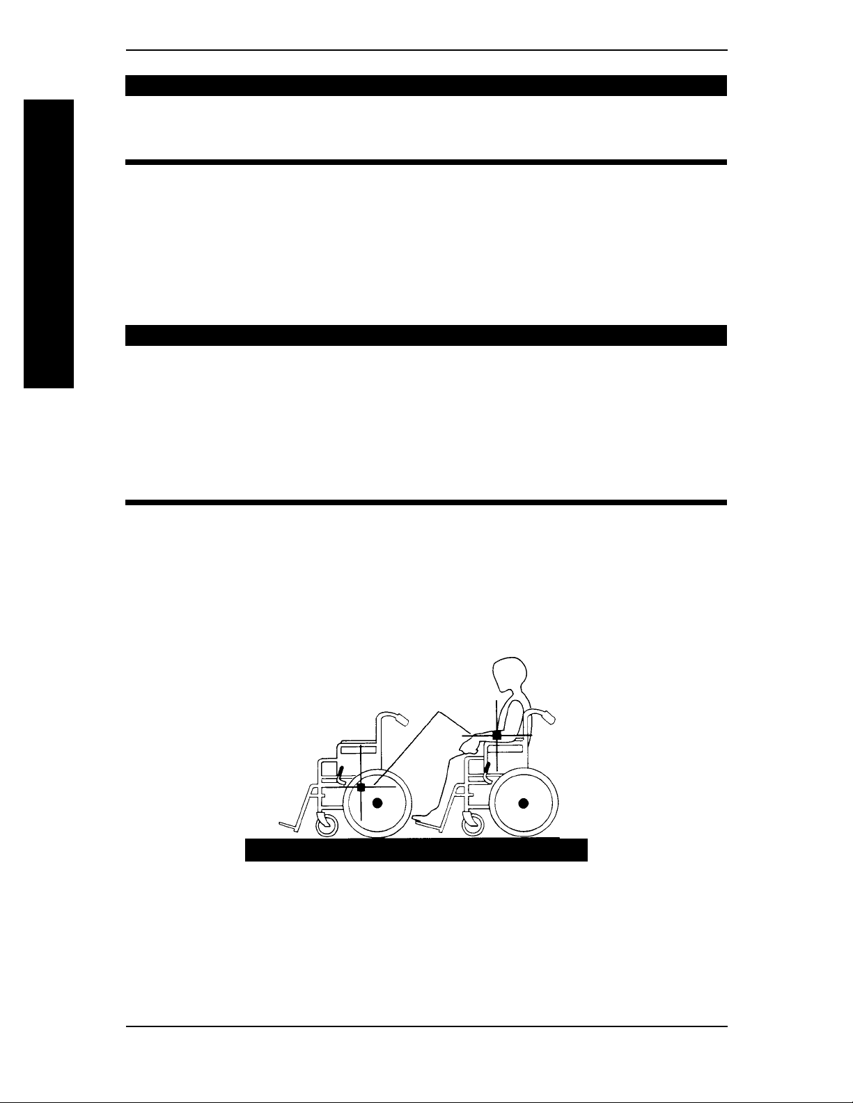
PERCENTAGE OF WEIGHT DISTRIBUTION
GENERAL GUIDELINES
GENERAL GUIDELINES
DO NOT attempt to reach objects if you have to move forward in the seat or
pick them up from the floor by reaching down between your knees.
The back height, seat depth, back angle, seating system, tilt angle, seat height,
size/position of the rear wheels, size/position of the front casters, as well as the
user condition directly relate to the stability of the wheelchair. Any change to
one (1) or any combination of the eleven (11) may cause the wheelchair to
decrease in stability. These adjustments MUST be performed by a qualified
technician.
Many activities require the wheelchair owner to reach, bend and transfer in and out of the
wheelchair. These movements will cause a change to the normal balance, the center of gravity,
and the weight distribution of the wheelchair. To determine and establish your particular safety
limits, practice bending, reaching and transferring activities in several combinations in the
presence of a qualified healthcare professional BEFORE attempting active use of the wheelchair.
Proper positioning is essential for your safety. When reaching, leaning, or bending forward, it is
important to use the front casters as a tool to maintain stability and balance.
WARNING
CENTER OF
GRAVITY
UNOCCUPIED OCCUPIED
Solara™ 14 Part No. 1080556 Rev. I
Page 15
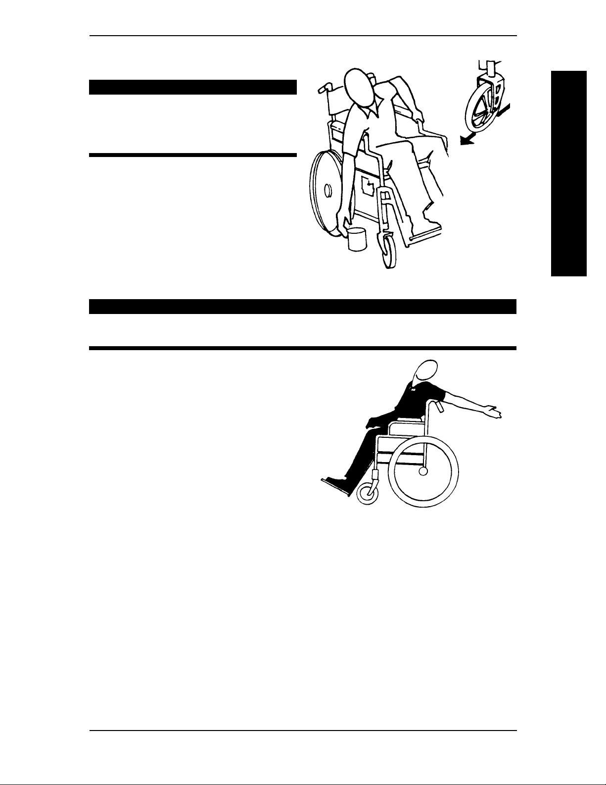
Reaching, Leaning and Bending Forward.
WARNING
DO NOT attempt to reach objects if
you have to move forward in the seat
or pick them up from the floor by
reaching down between your knees.
Position the front casters so that they are
extended as far forward as possible and
engage wheel locks.
GENERAL GUIDELINES
Reaching, Leaning - Backwards.
PROCEDURE 1GENERAL GUIDELINES
GENERAL GUIDELINES
WARNING
DO NOT lean over the top of the back upholstery. This will change your center
of gravity and may cause you to tip over.
Position wheelchair as close as possible to the
desired object. Point front casters forward to
create the longest possible wheelbase. Reach
back only as far as your arm will extend
without changing your sitting position.
Part No. 1080556 Rev. I 15 Solara™
Page 16
PROCEDURE 1 GENERAL GUIDELINES
TIPPING
DO NOT tip the wheelchair without assistance.
When tipping the wheelchair, an assistant should grasp the back of the wheelchair on a nonremovable (non-detachable) part. Inform the wheelchair occupant before tipping the wheelchair
and remind him/her to lean back. Be sure the occupant’s feet and hands are clear of all wheels
and/or pinch points.
After mastering the techniques of tipping the wheelchair, use one (1) of the following methods
to tackle curbs, short stairs, etc.
TIPPING - CURBS: METHOD 1 - WHEELCHAIR WITH STEP TUBES:
GENERAL GUIDELINES
Place foot on the step tube and begin to tilt the wheelchair toward you. Apply a continuous
downward motion until the balance point is achieved and the front casters clear the curb. At
this point, the assistant will feel a difference in the weight distribution.
When lowering the front casters of the wheelchair, DO NOT let the wheelchair
drop the last few inches to the ground. This could result in injury to the occupant and/or damage to the wheelchair.
WARNING
GENERAL GUIDELINES
WARNING
Step Tube
METHOD 1 - WHEELCHAIR WITH STEP TUBES
Roll the wheelchair forward and slowly lower the front of the wheelchair in one continuous
movement onto the sidewalk. Do not let the wheelchair drop the last few inches to the
ground. This could result in injury to the occupant. Push the wheelchair forward until the rear
wheels roll up and over the curb.
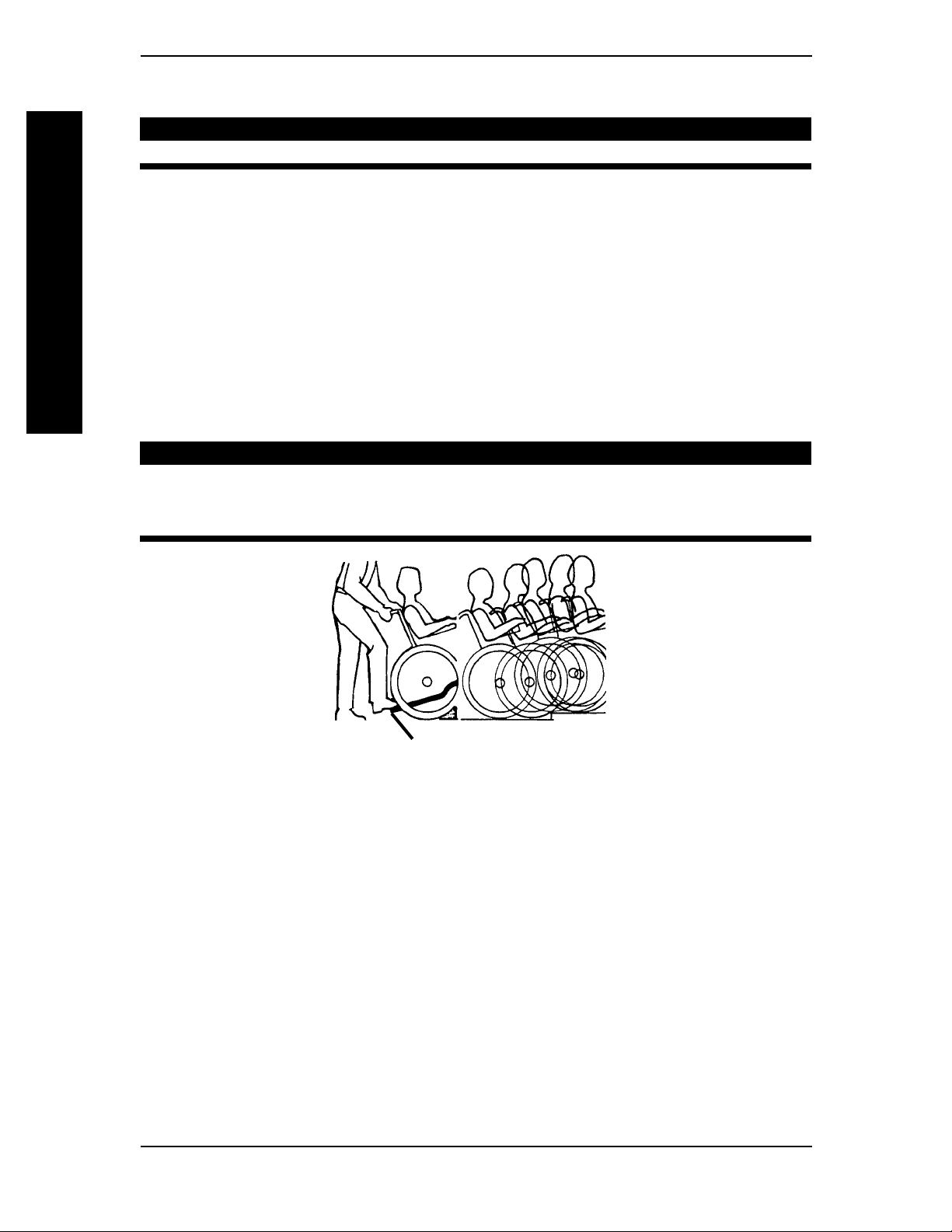
TIPPING - CURBS: METHOD 2 - WHEELCHAIR
This method requires two (2) assistants. The second assistant should be positioned at the front
of the wheelchair lifting upward on a non-removable (non-detachable) part of the wheelchair
frame when lifting the wheelchair and stabilizing the wheelchair when the wheelchair is being
lowered to the ground.
Rotate the anti-tippers so the anti-tip wheels are pointing up. The first assistant should stand
on the sidewalk and turn the wheelchair so that the rear wheels are against the curb. The
wheelchair should be tilted back to the balance point and, in one continuous upward movement, the rear wheels should be pulled up and over the curb. DO NOT return the front
casters to the ground until the wheelchair has been pulled backward far enough for the front
casters to clear the edge of the curb.
Solara™ 16 Part No. 1080556 Rev. I
WITHOUT STEP TUBEWITHOUT STEP TUBE
WITHOUT STEP TUBE
WITHOUT STEP TUBEWITHOUT STEP TUBE
Page 17
WARNING
When lowering the front casters of
the wheelchair, DO NOT let the
wheelchair drop the last few inches to
the ground. This could result in injury
to the occupant and/or damage to the
wheelchair.
Roll the wheelchair backward and SLOWLY
lower the wheelchair in one continuous
movement. DO NOT let the wheelchair drop
the last few inches to the ground. This could
GENERAL GUIDELINES
result in injury to the occupant.
STAIRWAYS
ALWAYS wear your seat/chest positioning strap. Inasmuch as the SEAT/
CHEST POSITIONING STRAP is an option on this wheelchair (You may order
with or without the Seat/Chest Positioning Strap), Invacare strongly recommends ordering the Seat/Chest Positioning Strap as an additional safeguard for
the wheelchair user.
PROCEDURE 1GENERAL GUIDELINES
GENERAL GUIDELINES
METHOD 2 - WHEELCHAIR
WITHOUT STEP TUBE
WARNING
Do not attempt to lift a wheelchair by lifting on any removable (detachable)
parts. Lifting by means of any removable (detachable) parts of a wheelchair
may result in injury to the user or damage to the wheelchair.
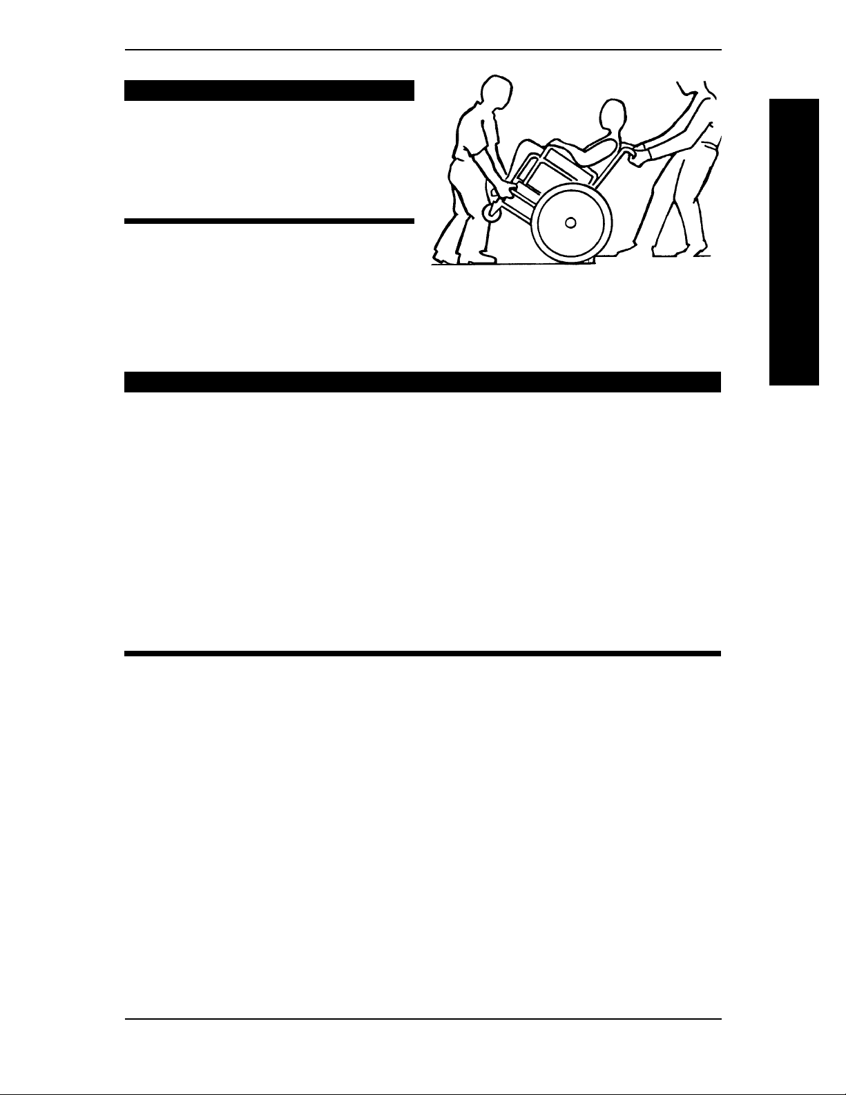
Extreme caution is advised when it is necessary to move an occupied wheelchair up or down the stairs. Invacare recommends that, if possible, the user be
removed from the wheelchair prior to moving. Invacare recommends using
two (2) assistants and making thorough preparations. Make sure to use ONLY
secure, non-detachable parts for hand-held supports.
Follow this procedure for moving the wheelchair between floors when an elevator is NOT
available:
1. If necessary, rotate the anti-tippers so the wheels are facing up.
2. After the wheelchair has been tilted back to the balance point, one assistant (in the rear)
backs the wheelchair up against the first step, while securely grasping a non-removable
(non-detachable) part of the wheelchair for leverage.
3. The second assistant, with a firm hold on a non-detachable part of the framework, lifts the
wheelchair up and over the stair and steadies the wheelchair as the first assistant places
one (1) foot on the next stair and repeats STEP 1.
4. The wheelchair should not be lowered until the last stair has been negotiated and the
wheelchair has been rolled away from the stairway.
5. If necessary, rotate the anti-tippers so the wheels are facing down.
Part No. 1080556 Rev. I 17 Solara™
Page 18
PROCEDURE 1 GENERAL GUIDELINES
DO NOT use an escalator to move a wheelchair between floors. Serious bodily
injury may occur.
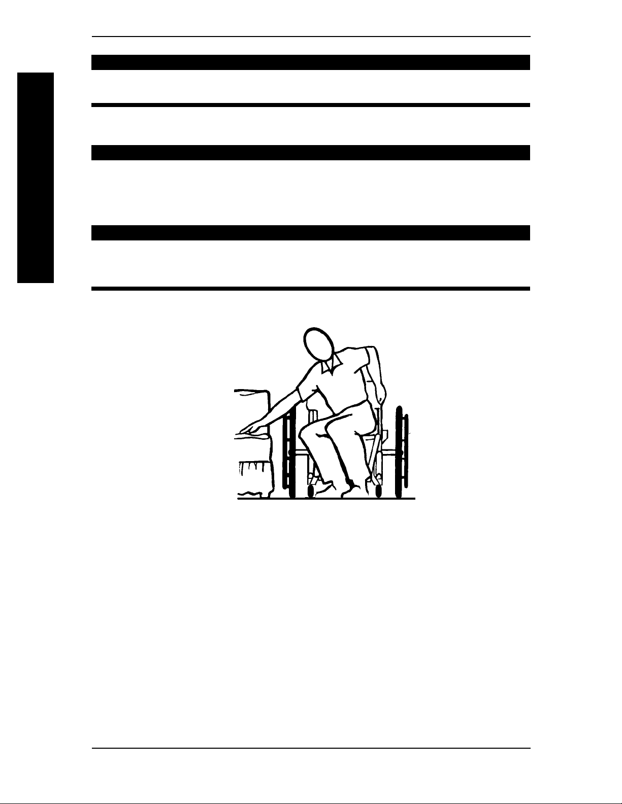
TRANSFERRING TO AND FROM OTHER SEATS
BEFORE attempting to transfer in or out of the wheelchair, every precaution
should be taken to reduce the gap distance. Turn both casters parallel to the
object you are transferring onto. Also be certain the wheel locks are engaged
to help prevent the wheels from moving.
GENERAL GUIDELINES
When transferring, position yourself as far back as possible in the seat. This will
help prevent broken screws, damaged upholstery and the possibility of the
wheelchair tipping forward.
NOTE: This activity may be performed independently provided you have adequate mobility and upper
body strength.
ESCALATORS? SORRY!
GENERAL GUIDELINES
WARNING
CAUTION
Position the wheelchair as close as possible along side the seat to which you are transferring, with
the front casters parallel to it. Remove or flip up the armrest. Engage wheel locks. Shift body
weight into seat with transfer.
During independent transfer, little or no seat platform will be beneath you. Use a transfer
board if at all possible.
Solara™ 18 Part No. 1080556 Rev. I
Page 19

This Procedure Includes the Following:
Safety Inspection Checklist
Troubleshooting
Maintenance/Transporting
SAFETY INSPECTION CHECKLIST
NOTE: Every six (6) months take your wheelchair to a qualified technician for a thorough inspection
and servicing. Regular cleaning will reveal loose or worn parts and enhance the smooth operation of
your wheelchair. To operate properly and safely, your wheelchair must be cared for just like any other
vehicle. Routine maintenance will extend the life and efficiency of your wheelchair.
Initial adjustments should be made to suit personal body structure and preference. Thereafter follow these
maintenance procedures:
ITEM
SAFETY INSPECTION
GENERAL
Wheelchair rolls straight (no excessive drag or pull to one side). X X
CLOTHING GUARDS
Inspect for bent or protruding metal. X X
Ensure all fasteners are secure. X X
ARMS - PROCEDURE 5
Secure but easy to release. X X
ARMREST - PROCEDURE 5
Inspect for rips in upholstery. X X
Base sits flush against arm tube. X X
FOAM HAND GRIPS
Ensure hand rips are not loose. X X
TRIGGER RELEASE LEVER AND CABLE - PROCEDURE 7
Cables completely release and handles return when released. X X
REAR WHEELS - PROCEDURE 8
Sealed bearings and axle nut tension correct. X X X
No excessive side movement/binding when lifted from ground
and spun. X X
HANDRIMS
Inspect for signs of rough edges or peeling finish. X X
FRONT CASTERS - PROCEDURE 8
Inspect axle for proper tension by spinning caster;
caster should come to a gradual stop. X X
Adjust bearing system if wheel wobbles noticeably or binds to stop. X X
CAUTION: As with any vehicle, the wheels and tires
should be checked periodically for cracks and wear,
and should be replaced.
TIRES - PROCEDURE 8
Inspect for flat spots and wear. X X
If pneumatic tires, check for proper inflation. X X
CAUTION: As with any vehicle, the wheels and tires
should be checked periodically for cracks and wear,
and should be replaced.
WHEEL LOCKS - PROCEDURE 9
Wheel locks do not interfere with tires when rolling. X X
Wheel locks easy to engage. X X
Pivot points free of wear or looseness. X X
CLEANING
Clean and wax all parts. X
Clean upholstery and armrests. X
Inspect axles are free from dirt, lint, etc. X
Inspect tilt slides and roller bearings are free from dirt, lint, etc. X
Initially
PROCEDURE 2SAFETY INSPECTION
Weekly Monthly
SAFETY INSPECTION
Periodically
Part No. 1080556 Rev. I 19 Solara™
Page 20

SAFETY INSPECTIONPROCEDURE 2
TROUBLESHOOTING
Chair Chair Sluggish Squeaks
Veers Veers Turn or Caster and Looseness
Right Left Performance Flutter Rattles in Chair SOLUTIONS
SAFETY INSPECTION
XX X
XX X Check that both
SAFETY INSPECTION
MAINTENANCE
MAINTENANCE SAFETY PRECAUTIONS
After ANY adjustments, repair or service and BEFORE use, make sure all attaching hardware is tightened securely - otherwise injury or damage may result.
DO NOT over tighten hardware attaching to the frame. This could cause
damage to the frame tubing.
SUGGESTED MAINTENANCE PROCEDURES
1. Keep quick-release axles free of dirt and lint to ensure positive locking and proper operation. Refer to ADJUSTING THE QUICK-RELEASE AXLE in PROCEDURE 8 of this manual.
Check tires for correct
and equal pressure.
XXXXCheck for loose nuts
and bolts.
casters
contact the
ground at the same time.
WARNING
CAUTION
WARNING
DO NOT use WD-40®, 3-in-1 oil®, or other penetrating lubricants on quickrelease axles. Otherwise, binding and/or damage to the wheelchair may occur.
2. Clean quick-release axles once (1) a week with a Teflon® lubricant.
WARNING
DO NOT use the wheelchair unless it has the proper tire pressure (p.s.i.). DO
NOT overinflate the tires. Failure to follow these suggestions may cause the
tire to explode and cause bodily harm.
3. If tires are pneumatic, recommended tire pressures will be listed on the side wall of the tires.
4. Periodically adjust wheel locks in correlation to tire wear. Refer to
JUSTMENT in PROCEDURE 9 of this manual.
5. Make sure that ALL bolts are tight before operating wheelchair.
WHEEL LOCK AD-
CAUTION
As with any vehicle, the wheels and tires should be checked periodically for
cracks and wear, and should be replaced.
6. The wheels and tires should be checked periodically for cracks and wear, and should be replaced.
7. Keep tilt slides and roller bearings free of dirt and lint to ensure proper operation of the
tilt mechanism.
Solara™ 20 Part No. 1080556 Rev. I
Page 21

TRANSPORTING PROCEDURE 3
This Procedure Includes the Following:
Transporting the Invacare Solara
TRANSPORTING THE INVACARE SOLARA
1. Remove the seating system. Refer to the seating system Owner's Manual for installation
and removal of the seating system.
2. Remove the footrests (PROCEDURE 4).
3. Remove the rear wheels (PROCEDURE 8).
4. Remove the armrests (PROCEDURE 5).
TRANSPORTING
5. Remove the stroller handle (if applicable) (PROCEDURE 6).
6. Pull back release cord and fold the back towards the front of the wheelchair (PROCEDURE 6).
TRANSPORTING
Part No. 1080556 Rev. I 21 Solara™
Page 22
This Procedure Includes the Following:
Installing/Removing
Adjusting Swingaway Footrest Height
Adjusting Adjustable Angle Flip-up Footplates
Composite/Articulating Footplate Heel Loop Replacement
Installing/Removing Elevating Legrest/Calfpad Assembly
Adjusting the Elevating Legrest/Calfpad Assembly
Swingaway Footrest
WARNING
FRONT RIGGINGSPROCEDURE 4
FRONT RIGGINGS
FRONT RIGGINGS
After ANY adjustments, repair or service and BEFORE use, make sure all
attaching hardware is tightened securely - otherwise injury or damage may
occur.
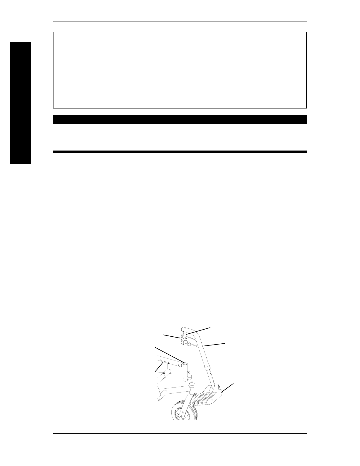
INSTALLING/REMOVING SWINGAWAY FOOTREST
(FIGURE 1)
INSTALLING
1. Turn the footrest to the side (open footplate is perpendicular to the wheelchair).
2. Insert the footrest assembly mounting pin into the mounting tube of the wheelchair frame.
3. Rotate the footrest towards the inside of the wheelchair until it locks into place.
NOTE: The footplate will be on the inside of the wheelchair when locked in place.
4. Repeat STEPS 1-3 for the other footrest assembly.
5. If necessary, adjust the footrest height. Refer to
HEIGHT in this procedure of the manual.
REMOVING
1. Push the footrest release lever inward while rotating the footrest outward.
ADJUSTING SWINGAWAY FOOTREST
2. Lift the footrest assembly out of the mounting pin of the wheelchair frame.
3. Repeat STEPS 1-2 for opposite side, if necessary.
Footrest Release
Lever
Mounting
Tube
Wheelchair
Frame
NOTE: Only 60° Front Rigging
shown for clarity. Others will attach
the same way.
Mounting Pin
Footrest
Assembly
Footplate
FIGURE 1 - INSTALLING/REMOVING SWINGAWAY FOOTREST
Solara™ 22 Part No. 1080556 Rev. I
Page 23
ADJUSTING SWINGAWAY FOOTREST HEIGHT
PROCEDURE 4FRONT RIGGINGS
HEIGHT ADJUSTMENT RANGES:
60° 13-17-inches
70° 13-17-inches
90° 5-8-inches
90° 5-11-inches (with 3-inch extension)
NOTE: If using ANY type of extension with the
ADJUSTABLE FLIP-UP FOOTPLATE, refer to
ADJUSTABLE ANGLE FLIP-UP FOOTPLATE PERPENDICULAR AND/OR INVERSION/EVERSION
ADJUSTMENT in this procedure of the manual.
FRONT RIGGINGS
60°, 70° and 70° Taper (FIGURE 2)
1. Remove the footrest from the wheelchair.
Refer to INSTALLING/REMOVING
SWINGAWAY FOOTREST in this procedure of the manual.
2. Remove the hex screw and coved spacer and slide the footrest up or down on its
mounting tube until the desired footrest height is achieved.
3. Reassemble the hex screw and coved spacer through the footrest upper support and
mounting tube as shown in FIGURE 2.
4. Securely tighten the hex screw and coved spacer.
Hex Screw
Coved
Spacer
Footrest
Footrest Upper
Support
Mounting
Tube
FIGURE 2 - ADJUSTING
SWINGAWAY FOOTREST
HEIGHT - 60°, 70° AND 70° TAPER
FRONT RIGGINGS
5. Install the footrest assembly onto the wheelchair. Refer to
SWINGAWAY FOOTREST in this procedure of the manual.
6. Repeat STEPS 1-5 for the opposite side of the wheelchair, if necessary.
INSTALLING/REMOVING
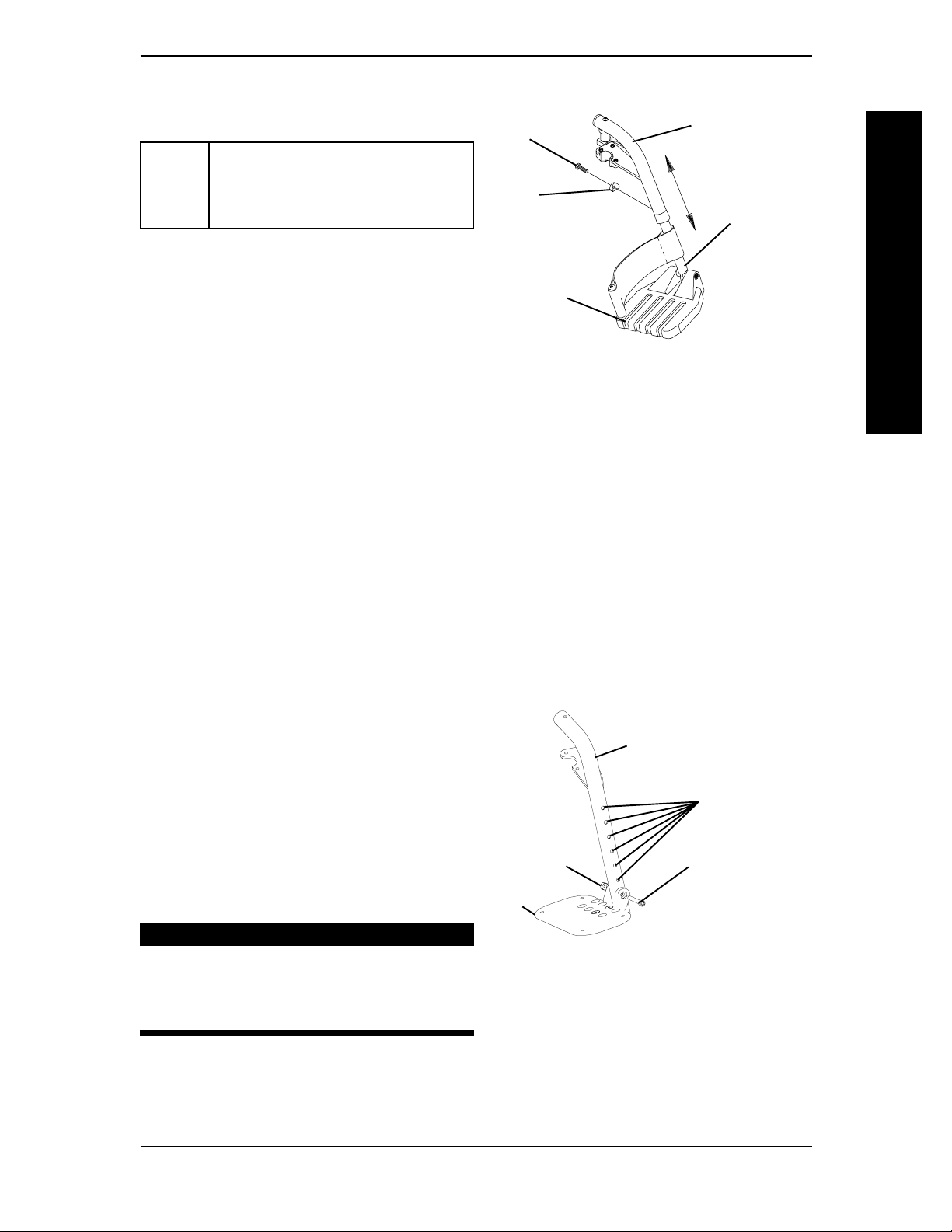
70° MFX AND 90° FOOTRESTS (FIGURE 3)
1. Remove any accessories that are attached
to the footrests.
2. Remove the socket bolt, coved washer
and locknut that secure the footplate to
the footrest support.
3. Reposition the footplate to the desired
height.
4. Reinstall the socket bolt through the
mounting holes of the footplate and
footrest support.
Locknut
Footplate
Footrest Support
WARNING
DO NOT overtighten socket bolt
and locknut. Footrest MUST be able
to rotate upward from the horizontal to the vertical position.
5. Secure the footplate to the footrest
support with the coved washer and
locknut.
FIGURE 3 - INSTALLING/REMOVING/
ADJUSTING THE FOOTREST(S) -
70° MFX AND 90° FOOTRESTS
Height
Adjustment
Holes
Socket Bolt
Part No. 1080556 Rev. I 23 Solara™
Page 24
INSTALLING ADJUSTABLE ANGLE FLIP-UP FOOTPLATE
HINGE (FIGURE 4)
1. Position the adjustable angle flip-up footplate hinge on the footrest support tube at the
desired height.
2. Position the hardware on the footrest support as shown in FIGURE 4.
3. Flip the footplate hinge to the UP position.
NOTE: The footplate hinge will fall to the DOWN position.
4. Tighten the socket screw and locknut that secure the footplate hinge to the footrest
support until the footplate hinge remains in the UP position.
5. Check the up and down motion of the footplate hinge to make sure the user of the
FRONT RIGGINGS
wheelchair can operate the footplates easily.
NOTE: If the footplate's motion is too tight, loosen the socket screw and locknut approximately
1/4-turn.
NOTE: If the footplate's motion is too loose, tighten the socket screw and locknut approximately
1/4-turn.
FRONT RIGGINGSPROCEDURE 4
FRONT RIGGINGS
Locknut
Footplate
Hinge
Footrest
Support
Tube
Socket
Screw
FIGURE 4 - INSTALLING ADJUSTABLE ANGLE
FLIP-UP FOOTPLATE HINGE
Solara™ 24 Part No. 1080556 Rev. I
Page 25

PROCEDURE 4FRONT RIGGINGS
COMPOSITE/ARTICULATING FOOTPLATE HEEL LOOP
REPLACEMENT (FIGURE 5)
DISASSEMBLY
COMPOSITE FOOTPLATE
Swingaway Footrest Assembly
Composite.
1. Remove the hex screw and coved spacer
that secure the lower footrest assembly
to the swing away footrest assembly.
2. Remove the lower footrest assembly.
3. Remove the phillips screw and locknut
that secure the heel loop to the footrest.
FRONT RIGGINGS
4. Slide heel loop off of the footrest.
Articulating.
1. Remove the phillips screws, washers and
spacers that secure the heel loop to the
articulating footplate.
REASSEMBLY
1. Replace heel loop.
2. Reverse the disassembly procedures.
NOTE: When securing the heel loop to the footrest assembly, tighten phillips screw until the spacer is secure.
INSTALLING/REMOVING ELEVATING LEGREST/CALFPAD
ASSEMBLY (FIGURE 6)
Hex Screw and Coved Spacer
Phillips Screw
Lower Footrest
Spacer
Heel
Loop
Locknut
Assembly
Spacer
ARTICULATING
FOOTPLATE
FIGURE 5 - COMPOSITE/
ARTICULATING FOOTPLATE
HEEL LOOP REPLACEMENT
FRONT RIGGINGS
Phillips
Screws
Washer
Heel
Loop
INSTALLING
1. Insert the footplate assembly into the
calfpad assembly and secure it with bolt and
nut.
2. Place legrest/calfpad assembly on the
outside of the wheelchair and insert
legrest mounting pin into the legrest
mounting tube on the wheelchair frame.
3. Rotate legrest/calfpad assembly toward the
inside of the wheelchair until it locks in
place.
NOTE: The calfpad of the legrest will be on the
inside of the wheelchair when locked in place.
4. Repeat STEPS 1-3 for the other legrest
assembly.
5. Adjust the footplate to the correct height by loosening the bolt and nut and sliding the
inner tube up or down until desired height is achieved. Securely tighten bolt and nut.
Legrest
Mounting
Tube
Wheelchair
Frame
Footplate Assembly
Legrest Mounting Pin
Release
Handle
Calfpad
Assembly
Bolt and
Nut
FIGURE 6 - INSTALLING/
REMOVING ELEVATING LEGREST/
CALFPAD ASSEMBLY
REMOVING
1. Push the legrest release handle inward while rotating the footrest outward.
2. Lift the legrest assembly out of the legrest mounting tube.
Part No. 1080556 Rev. I 25 Solara™
Page 26

ADJUSTING THE ELEVATING LEGREST/CALFPAD
ASSEMBLY (FIGURE 7)
ADJUSTING THE LEGREST
1. Raise legs until the desired height is obtained by lifting up on the footplate assembly.
2. To reposition legrest to normal position, support leg with one (1) hand and push release
lever forward with other hand.
ADJUSTING THE CALFPAD
1. Turn the calfpad towards the outside of the wheelchair.
2. Slide the calfpad up or down until the desired position is obtained.
FRONT RIGGINGS
3. To secure the calfpad, turn the calfpad towards the inside of the wheelchair.
FRONT RIGGINGSPROCEDURE 4
FRONT RIGGINGS
Release Lever
Adjusts Height
Calfpad Rotated for
Height Adjustment
Calfpad
FIGURE 7 - ADJUSTING THE ELEVATING LEGREST/CALFPAD ASSEMBLY
Solara™ 26 Part No. 1080556 Rev. I
Page 27

This Procedure Includes the Following:
Installing/Removing/Adjusting Dual Point Armrest
Using/Installing/Adjusting Locking Cantilever Arms
Using/Installing/Adjusting Non-Locking Cantilever Arms
Arm Pad Replacement for Cantilever Arms
PROCEDURE 5ARMS
ARMS
Installing/Removing T-Arms
Adjusting the T-Arms
Adjusting Transfer Assists and/or Side Guards - Arms
WARNING
After ANY adjustments, repair or service and BEFORE use, make sure all attaching hardware is tightened securely - otherwise injury or damage may occur.
INSTALLING/REMOVING/ADJUSTING DUAL POINT
ARMREST (FIXED AND ADJUSTABLE HEIGHT) (FIGURE 1)
WARNING
Make sure the locking mechanism is secured BEFORE using the wheelchair.
INSTALLING ARMREST
1. Unlock armrest assembly by flipping the arm assembly release lever located on the side rail
to the UP (HORIZONTAL) position as shown in DETAIL "A" .
NOTE: Armrest locks MUST be in the unlocked position when placing arm into the arm sockets.
ARMS
2. Install armrest assembly into the arm sockets.
3. When installed, lock the armrest assembly by pressing the release lever into the DOWN
(VERTICAL) position as shown in DETAIL "A".
4. Repeat STEPS 1-3 for the opposite side of the wheelchair.
5. If necessary, adjust the armrest height. Refer to
of the manual.
ADJUSTING ARMREST in this procedure
REMOVING ARMREST
1. Unlock armrest assembly by flipping the arm assembly release lever located on the side rail
to the UP (HORIZONTAL) position as shown in DETAIL "A".
2. Pull up on the armrest assembly to remove the armrest from the arm socket.
3. Repeat STEPS 1-2 for opposite side of wheelchair, if necessary.
Part No. 1080556 Rev. I 27 Solara™
Page 28

ARMS
PROCEDURE 5 ARMS
ADJUSTING ARMREST
1. Unlock the armrest assembly by flipping the armrest release lever on the top front of the
arm to the UP (HORIZONTAL) position as shown in DETAIL "A".
2. Adjust armrest assembly to desired height.
3. Lock the armrest assembly by pressing the release lever into the DOWN (VERTICAL)
position as shown in DETAIL "A".
4. Pull up on the armrest assembly to ensure the armrest is locked in place.
5. Repeat STEPS 1-4 for opposite side of wheelchair, if necessary.
Armrest
Assembly
ARMS
Adjusts Armrest
Height
Armrest Release Lever
DETAIL "A"DETAIL "A"
DETAIL "A"
DETAIL "A"DETAIL "A"
Locked - Down
(Vertical)
Unlocked - Up
(Horizontal)
Arm Socket
FIGURE 1 - INSTALLING/REMOVING/ADJUSTING DUAL POINT
ARMREST
Solara™ 28 Part No. 1080556 Rev. I
Page 29

USING/INSTALLING/ADJUSTING LOCKING
CANTILEVER ARMS
USING LOCKING CANTILEVER ARMS (FIGURE 2)
1. Pull the actuator of the locking mechanism
towards the front of the wheelchair.
PROCEDURE 5ARMS
2. While holding the actuator of the locking
mechanism, pull up on the cantilever arm.
NOTE: If necessary, the locking mechanism in the
cantilever arm can be repositioned so the
cantilever arm will open down instead of up. For
this adjustment, contact a qualified technician.
3. To lock the cantilever arm, push down
until there is an audible click.
4. Pull up on the cantilever arm to make sure
it is locked in place.
REAR
Cantilever Arm
Actuator
FRONT
FIGURE 2 - USING LOCKING
CANTILEVER ARMS
INSTALLING LOCKING CANTILEVER ARMS (FIGURE 3)
NOTE: When removing the locknuts and washers from the cantilever arm assembly, leave the top hex
bolt, coved washers and spacer (between adjustment plate and cantilever arm) in place.
1. Slide the partially assembled cantilever arm assembly w/mounting hardware through the
back cane. Make sure the adjustment plate is towards the inside of the wheelchair.
ARMS
NOTE: This includes top hex bolt, coved washers and spacer (between adjustment plate and cantilever arm).
2. Slide the bottom hex bolt (w/coved washer) through the adjustment plate and back cane.
3. Securely tighten the cantilever arm to the wheelchair with two (2) locknuts and washers.
4. Adjust the angle of the cantilever arm, if necessary. Refer to
CANTILEVER ARM ANGLE in this section of the manual.
ADJUSTING LOCKING
ADJUSTING LOCKING CANTILEVER ARM HEIGHT (FIGURE 3)
NOTE: When removing the locknuts and washers from the cantilever arm assembly, leave the top hex
bolt, coved washers and spacer (between adjustment plate and cantilever arm) in place.
1. Remove the two (2) locknuts and washers securing the cantilever arm assembly to the back
cane.
2. Remove the cantilever arm assembly with hardware from the back cane.
3. Perform STEPS 1-4 in
arm at the desired height.
Part No. 1080556 Rev. I 29 Solara™
INSTALLING LOCKING CANTILEVER ARM to reposition the
Page 30

PROCEDURE 5 ARMS
Back Cane
ARMS
Adjustment Plate
Coved Washers
Actuator
Spacer
Top Hex Bolt
and Coved Washer
Cantilever Arm
Bottom Hex Bolt
FIGURE 3 - INSTALLING LOCKING CANTILEVER ARMS /
ADJUSTING LOCKING CANTILEVER ARM HEIGHT
Locknuts
Washers
ADJUSTING LOCKING CANTILEVER ARM ANGLE
(FIGURE 4)
NOTE: This adjustment is recommended if the back angle has been changed.
1. Flip the cantilever arm up and out of the way.
2. Remove the locknut that secures the locking pin to the arm adjustment plate.
3. Refer to FIGURE 4 to determine the mounting hole in the arm adjustment plate that will
be used to correspond to the back angle.
4. Securely tighten the locking pin and washer to the adjustment plate with a locknut.
5. Repeat STEPS 1-4 for the opposite side, if necessary.
Solara™ 30 Part No. 1080556 Rev. I
Page 31

PROCEDURE 5 ARMS
ARMS
90°
Back Angle Bracket
Arm Adjustment Plate
110°
Back Angle Bracket
Arm Adjustment Plate
100°
Back Angle Bracket
Arm Adjustment Plate
ARMS
120°
Back Angle Bracket
Arm Adjustment Plate
Arm Adjustment Plate
Locknut
Locking Pin
Washer
FIGURE 4 - ADJUSTING LOCKING CANTILEVER ARM ANGLE
Part No. 1080556 Rev. I 31 Solara™
Page 32

PROCEDURE 5 ARMS
USING/INSTALLING/ADJUSTING NON-LOCKING
CANTILEVER ARMS
WARNING
DO NOT use lap trays with non-locking cantilever arms.
ARMS
USING NON-LOCKING CANTILEVER ARMS (FIGURE 5)
1. Pull the end of the cantilever arm down
to lower the cantilever arm.
Back Cane
REAR
2. Pull the end of the cantilever arm up to
move it out of the way.
Cantilever Arm
FIGURE 5 - USING NON-LOCKING
CANTILEVER ARMS
INSTALLING NON-LOCKING CANTILEVER ARMS (FIGURE 6)
1. Remove the locknut and washer from the lower hex bolt installed on the non-locking
cantilever arm.
2. Slide the hex bolt of the cantilever arm assembly into the desired mounting hole on the
back cane.
3. Secure the cantilever arm to the wheelchair with a washer and locknut as shown in
FIGURE 6.
ARMS
4. Adjust the angle of the cantilever arm, if necessary. Refer to
ING CANTILEVER ARM ANGLE in this section of the manual.
ADJUSTING NON-LOCKING
CANTILEVER ARM HEIGHT
Coved Washers
and Spacer
(FIGURE 6)
1. Remove the locknut and washer from
the lower hex bolt securing the cantilever arm to the back cane.
2. Slide the cantilever arm assembly out of
the back cane.
3. Reposition the cantilever arm assembly
to the desired mounting hole.
4. Secure the cantilever arm to the wheelchair with a washer and locknut as
shown in FIGURE 6.
Lower Hex Bolt
FIGURE 6 - INSTALLING NON-
LOCKING CANTILEVER ARMS/
ADJUSTING NON-LOCKING
ADJUSTING NON-LOCK-
Back Cane
Locknut
Washer
Cantilever Arm
CANTILEVER ARM HEIGHT
Solara™ 32 Part No. 1080556 Rev. I
Page 33

PROCEDURE 5ARMS
ADJUSTING NON-LOCKING CANTILEVER ARM ANGLE (FIGURE 7)
1. Loosen the mounting screw securing the cam to the cantilever arm.
2. Rotate the cam until the desired angle (DETAIL "B" of FIGURE 7) is achieved.
3. Tighten the mounting screw securing the cam to the cantilever arm.
ARMS
DETAIL "A" -
SIDE VIEW OF CAM
Back Cane
0° ARM ANGLE
Back Cane
Cam
Cantilever
Arm
DETAIL "B" - CAM POSITIONS
4° ARM ANGLE
Back Cane
Cam
Cam
ARMS
Back Cane
Cantilever Arm
8° ARM ANGLE
Back Cane
Cam
12° ARM ANGLE
Back Cane
Cam
NOTE: All arm angles are relative to the back cane.
16° ARM ANGLE
Back Cane
Cam
FIGURE 7 - ADJUSTING NON-LOCKING CANTILEVER ARM ANGLE
Part No. 1080556 Rev. I 33 Solara™
Page 34

PROCEDURE 5 ARMS
ARM PAD REPLACEMENT FOR CANTILEVER ARMS
(FIGURE 8)
1. Remove the mounting screws from the armrest pad.
2. Replace with NEW armrest pad.
3. Secure with existing hardware.
ARMS
DESK LENGTH ARM PADS
Armrest Pad
Cantilever
Arm Tube
Mounting Screws
FULL LENGTH ARM PADS
Cantilever
Arm Tube
Mounting Screws
FIGURE 8 - ARM PAD REPLACEMENT FOR CANTILEVER ARMS
INSTALLING/REMOVING T-ARMS (FIGURE 9)
INSTALLING T-ARMS
1. Position the T-arm over the T-arm
socket on the wheelchair frame.
NOTE: Make sure the locking lever is towards the
front of the wheelchair.
2. Slide T-arm into T-arm socket until the
locking lever is in the slot in the T-arm
socket and an audible "click" is heard.
ARMS
Arm Pad
Cantilever
Slide Tube
T-Arm
3. Pull up on T-arm to make sure T-arm is
locked in place.
NOTE: If the T-arm does not slide in the T-arm socket
as desired, adjust the T-arm socket. Refer to
ING THE T-ARMS in this procedure of the manual.
4. Adjust the T-arm for desired height, width
and depth, if necessary. Refer to
THE T-ARMS in this procedure of the
manual.
5. Repeat STEPS 1-4 for opposite side of
wheelchair.
ADJUST-
ADJUSTING
Wheelchair
Frame
T-Arm
Socket
FIGURE 9 - INSTALLING/
REMOVING T- ARMS
Locking Lever
(towards the front
of the wheelchair)
Slot
REMOVING T-ARMS
1. Press in on the locking lever and lift the T-arm straight up and out of the T-arm socket.
NOTE: If the T-arm does not slide up and down in the T-arm socket as desired, adjust the T-arm socket.
Refer to
2. Repeat STEP 2 for opposite side of the wheelchair.
Solara™ 34 Part No. 1080556 Rev. I
ADJUSTING THE T-ARMS in this procedure of the manual.
Page 35

PROCEDURE 5ARMS
ADJUSTING THE T-ARMS
ADJUSTING T-ARM HEIGHT (FIGURE 10)
1. Unlock the T-arm by flipping the T-arm release lever towards the inside of the wheelchair.
NOTE: If necessary, pull out on the T-arm release lever and rotate 180° so it can be flipped towards
the outside of the wheelchair.
ARMS
2. Slide the T-arm to one (1) of:
A. Low Height T-Arms - Nine (9) positions.
B. High Height T-Arms - Seven (7) positions.
NOTE: If the inside T-arm post does not slide up and down in the outside T-arm post as desired,
perform one (1) of the following:
A. Tighten - Tightening the set screws on the outside T-arm post will make it more
difficult to move the inside T-arm post up and down.
B. Loosen - Loosening the set screws on the outside T-arm post will make it easier
to move the inside T-arm post up and down.
3. Lock the T-arm by flipping the T-arm release lever towards the front of the wheelchair.
Inside T-Arm
Post
T-Arm Release Lever
- Locked Position
T-Arm Release Lever
- Unlocked Position
ARMS
Set
Screws
Outside T- Arm Post
FIGURE 10 - ADJUSTING T-ARM HEIGHT
ADJUSTING T-ARM WIDTH (FIGURE 11)
1. Remove the two (2) phillips screws that secure the arm pad to the arm tube.
2. Turn the arm pad around and reposition the arm pad on the arm tube.
3. Re-secure the arm pad to the arm tube with the two (2) phillips screws. Tighten securely.
4. Repeat for the opposite side, if necessary.
Arm Pad
Phillips Screw
Arm Tube
Phillips Screw
FIGURE 11 - ADJUSTING T-ARM WIDTH
Part No. 1080556 Rev. I 35 Solara™
Page 36

ARMS
PROCEDURE 5 ARMS
ADJUSTING T-ARM DEPTH (FIGURE 12)
1. Remove the two (2) phillips screws that
secure the arm pad to the arm tube.
2. Remove the two (2) socket screws that
secure the arm tube to the T-arm post.
3. Reposition the arm tube on the T-arm post:
A. Desk Length Arms - to one (1) of
three (3) positions depending on the
desired arm pad depth.
B. Full Length Arms - to one (1) of five
(5) positions depending on the desired
arm pad depth.
NOTE: Additional positions are obtainable by turning
the arm tube 180°.
4. Re-secure the arm tube to the T-arm post with the two (2) socket screws. Torque to
60-70 in./lbs.
5. Reattach the arm pad to the arm tube with the two (2) phillips screws. Tighten securely.
Arm Pad
Socket
Screws
Phillips
Screw
T-Arm Post
FIGURE 12 - ADJUSTING T-ARM
DEPTH
Arm Tube
NOTE: If
necessary,
turn arm
tube 180°
to obtain
two (2)
positions.
Phillips Screw
ARMS
6. Repeat for the opposite side, if necessary.
ADJUSTING T-ARM SOCKETS (FIGURE 13)
NOTE: Perform this procedure if the T-arm is too loose in the socket or does not easily slide up and
down in the socket.
1. Remove the rear wheels from the wheelchair, if necessary. Refer to
INSTALLING REAR WHEELS in PROCEDURE 7 of this manual.
2. Loosen, but do not remove the four (4)
hex screws and washers that secure
T-arm socket to T-arm clamp.
NOTE: The T-arm socket will disassemble if the four
(4) hex screws and washers are removed.
3. Slide the T-arm into the T-arm socket
until the locking lever is in the slot in the
T-arm socket and an audible "click" is
heard.
4. Squeeze the T-arm socket the T-arm
clamp together until the socket is flush
with the
T-arm.
REMOVING/
T-Arm
T-Arm Clamp
Hex Screws and
Washers
Hex Screws and
Washers
Slot
Locking Lever
T-Arm Socket
FIGURE 13 - ADJUSTING T-ARM
SOCKETS
5. While holding the T-arm socket and the T-arm clamp together, tighten the four (4) hex
screws and washers. Tighten securely.
6. Press in on the locking lever and lift the T-arm straight up and out of the T-arm socket.
7. Repeat STEPS 3-6, if necessary until the T-arm slides in the T-arm socket as desired.
8. If necessary, install rear wheels. Refer to
PROCEDURE 7 of this manual.
Solara™ 36 Part No. 1080556 Rev. I
REMOVING/INSTALLING REAR WHEELS in
Page 37

PROCEDURE 5ARMS
ADJUSTING T-ARM TRANSFER ASSISTS AND/OR SIDE
GUARDS (FIGURE 14)
1. Remove the T-arm from the wheelchair. Refer to INSTALLING/REMOVING T-ARMS in
this procedure of the manual.
2. Remove the two (2) socket screws that secure the side guard to the bottom clamp.
ARMS
NOTE: Adjusting the side guards will directly affect the position of the transfer assist.
3. Perform one (1) of the following:
Small Side Guards - Move the bottom clamp up one (1) of two (2) mounting positions in the side
guard.
Large Side Guards - Move the bottom clamp up one (1) of three (3) mounting positions in the side
guard.
4. Re-secure the side guard to the bottom clamp with the two (2) socket screws.
5. Install the T-arm onto the wheelchair. Refer to INSTALLING/REMOVING T-ARMS in
this procedure of the manual.
Side Guard
T-Arm
Transfer Assist
ARMS
Socket Screws
Bottom Clamp
FIGURE 14 - ADJUSTING T-ARM TRANSFER ASSISTS AND/OR SIDE
GUARDS
Part No. 1080556 Rev. I 37 Solara™
Page 38

This Procedure Includes the Following:
Folding/Unfolding Back Assembly
Installing/Removing the Stroller Handles
Installing/Removing/Adjusting the Adjustable Angle Stroller Handles
BACK/SEATPROCEDURE 6
Installing/Replacing Seat Positioning Straps
Installing/Replacing Chest Positioning Straps
Installing/Replacing The Back Upholstery
Installing the Seat Cushion
BACK/SEAT
After ANY adjustments, repair or service and BEFORE use, make sure all attaching hardware is tightened securely - otherwise injury or damage may result.
FOLDING/UNFOLDING BACK ASSEMBLY (FIGURE 1)
The back MUST be locked securely in place BEFORE using the wheelchair.
NOTE: When folding or unfolding the back, make sure the back release cord does not get caught in the
release latches.
1. Do one (1) of the following:
BACK/SEAT
WARNING
WARNING
A. UNFOLD - Push/pull the back towards rear of wheelchair until it locks in place.
B. FOLD - Pick up on the back release cord and push the back towards the front
of the wheelchair.
Back Release Cord
Release Latch
FIGURE 1 - FOLDING/UNFOLDING BACK ASSEMBLY
Solara™ 38 Part No. 1080556 Rev. I
Page 39

BACK/SEAT
PROCEDURE 6
INSTALLING/REMOVING THE STROLLER HANDLES
(FIGURE 2)
INSTALLING
1. Remove the plug buttons from both back canes, if necessary.
2. Slide the stroller handle into the back canes.
3. Align the mounting holes of the stroller handle and the back canes.
4. Press the button on the quick-release pin and insert the quick-release pin through the
back cane and stroller handle.
BACK/SEAT
BACK/SEAT
5. Release the button on the quick-release pin.
6. Pull on the stroller handle to make sure it is locked securely in place.
REMOVING
1. Push in the button of the quick-release pins.
2. Pull out the quick-release pins that secures the stroller handle to the back canes.
3. Remove the stroller handle from the wheelchair and discard.
4. Install the NEW stroller handle. Refer to
INSTALLING THE STROLLER HANDLES in this
procedure of the manual.
Stroller Handle
Mounting
Holes
Back Cane
Button
Quick-Release Pin
FIGURE 2 - INSTALLING/REMOVING THE STROLLER HANDLES
Part No. 1080556 Rev. I 39 Solara™
Page 40

INSTALLING/REMOVING/ADJUSTING THE ADJUSTABLE
ANGLE STROLLER HANDLES
NOTE: Adjustable angle stroller handles are bolted onto recliners ONLY.
INSTALLING (FIGURE 3)
1. Remove plug buttons from both back canes.
2. Slide the adjustable height stroller handle into the back canes.
3. Align the mounting holes of the adjustable angle stroller handle and the back cane.
4. Secure adjustable angle stroller handle to the back canes with the two (2) quick-release
BACK/SEAT
BACK/SEATPROCEDURE 6
BACK/SEAT
pins or the two (2) bolts and locknuts.
5. If necessary, adjust the height. Refer to
ADJUSTING in this procedure of the manual.
REMOVING (FIGURE 3)
1. Press and hold the buttons on the quick-release pins
2. Remove the adjustable angle stroller handle from the back cane.
3. Install plug buttons.
NOTE: Plug buttons not shown for clarity.
DETAIL "A" -
QUICK-RELEASE
PIN INSTALLED
Quick-Release Pin
(or bolt and locknut -
Recliners ONLY)
Stroller Handle
NOTE: Bolts and locknuts not shown. Bolts and
locknuts install in same location as quick-release
pins.
Back Cane
Quick-Release Pin
(or bolt and locknut
- Recliners ONLY)
Back Cane
Detent
Ball
FIGURE 3 - INSTALLING/REMOVING THE ADJUSTABLE ANGLE
STROLLER HANDLES
Solara™ 40 Part No. 1080556 Rev. I
Page 41

BACK/SEAT
PROCEDURE 6
ADJUSTING (FIGURE 4)
1. Flip both release levers to the unlocked position.
2. Adjust stroller handle to desired angle.
3. Flip both release levers to the locked position.
4. Push down on stroller handle to ensure release levers hold the desired position of the
stroller handle.
5. If release levers do not hold the position, tighten the release lever by performing the
following:
BACK/SEAT
BACK/SEAT
A. Flip release lever to the unlocked position.
B. Rotate thumbscrew CLOCKWISE one (1) revolution.
NOTE: When tightening the release lever, the release lever must be able to close completely into the
locked position. Otherwise, the release levers will not hold the desired angle.
C. Flip release levers to the locked position.
NOTE: If the release levers do not close completely into the locked position, rotate the thumbscrew on each release lever COUNTERCLOCKWISE 1/2 revolution.
D. Repeat STEPS A-C for opposite release lever.
E. Push down on stroller handle to ensure release levers hold the desired position of
the stroller handle.
F. Repeat STEPS A-E until release levers hold the position.
Stroller Handle
Thumbscrew
Release
Lever
LOCKED
POSITION
FIGURE 4 - ADJUSTING THE ADJUSTABLE ANGLE STROLLER HANDLES
Part No. 1080556 Rev. I 41 Solara™
Page 42

INSTALLING/REPLACING SEAT POSITIONING STRAPS
(FIGURE 5)
INSTALLING
1. Remove the hex screw and locknut that secures the back cane to the back plate.
2. Position the seat positioning strap against the back plate.
3. Install the hex screw through the seat positioning strap, coved spacers and back cane.
4. Securely tighten the seat positioning strap to the wheelchair with the locknut.
5. Repeat STEPS 1-4 for opposite side.
BACK/SEAT
REPLACING
1. Remove the hex screw, locknut and seat positioning strap from the back plate of the wheelchair
2. Discard EXISTING seat positioning strap.
BACK/SEATPROCEDURE 6
BACK/SEAT
frame.
3. Install the NEW seat positioning strap to the wheelchair. Refer to
ING STRAPS in this procedure of the manual.
Back Plate
Seat Positioning Strap
Hex Screw
INSTALLING SEAT POSITION-
Back Cane
Locknut
Coved Spacers
FIGURE 5 - INSTALLING/REPLACING SEAT POSITIONING STRAPS
Solara™ 42 Part No. 1080556 Rev. I
Page 43

BACK/SEAT
PROCEDURE 6
INSTALLING/REPLACING CHEST POSITIONING STRAPS
(FIGURE 6)
INSTALLING
Back Cane
1. Position the chest positioning strap to one
NOTE: The standard recommended position for the chest
positioning strap is in the top hole of the back cane, but
may be mounted according to the user's needs.
BACK/SEAT
2. Secure the chest positioning strap to the
3. Repeat STEPS 1-2 for opposite side.
REPLACING
1. Remove the hex screw that secures the chest positioning strap to the back cane.
2. Discard EXISTING chest positioning strap.
3. Repeat STEPS 1-2 for opposite side, if necessary.
4. Install the NEW chest positioning strap. Refer to
INSTALLING/REPLACING THE BACK UPHOLSTERY
(FIGURE 7)
(1) of the holes on the back cane.
back canes with the NEW/EXISTING hex
screw and locknut as shown in FIGURE 9.
STRAPS in this procedure of the manual.
Locknut
BACK/SEAT
Hex Screw
Chest Positioning Strap
FIGURE 6 - INSTALLING/ REPLACING
CHEST POSITIONING STRAP
INSTALLING CHEST POSITIONING
INSTALLING
1. Position the back upholstery on the back
cane as shown in FIGURE 7.
2. Starting with the top two (2) mounting
holes secure the back upholstery to the
back canes with the ten (10) phillips
screws and washers.
Back
Cane
Washer
Phillips
Screw
Back
Upholstery
REPLACING
1. Remove the ten (10) phillips screws and
washers that secure the back upholstery
to the back canes.
2. Remove existing back upholstery from
back canes.
FIGURE 7 - INSTALLING/
REPLACING THE BACK
UPHOLSTERY
3. Install new back upholstery onto the back
canes.
4. Install the ten (10) phillips screws and washers that secure the back upholstery to the back
canes.
Part No. 1080556 Rev. I 43 Solara™
Page 44

BACK/SEATPROCEDURE 6
INSTALLING THE SEAT CUSHION (FIGURE 8)
WARNING
The seat cushion IS NOT designed for use in the treatment of pressure sores or by
individuals at risk of developing pressure sores.
Your therapist and physician should be consulted if you have any questions regarding
weight relief, self-examination of the skin, or individual limitations and needs.
Make sure the hook and loop fastening strips are securely attached between the
seat pan and cushion before using.
BACK/SEAT
The cover is designed to protect the foam against a user’s incontinence and to
provide fire retardency so the cushion must not be used without its cover. If the
cover is torn, it must be replaced.
Machine wash cold. Gentle cycle. Mild detergent. NO fabric softeners or bleach.
Tumble dry low or air dry. Warm or hot water or high dryer heat will reduce
flame retardancy.
Wipe down surfaces with a slightly dampened cloth. DO NOT submerge cushion in
water. If cushion foam becomes contaminated because of incontinence, it should be
replaced beause the foam is absorbent and cannot be cleaned.
1. Perform one (1) of the following:
BACK/SEAT
CAUTION
A. FLUSH MOUNT SEAT PAN - Position the cushion with the flap toward the REAR of the
seat pan.
B. DROP MOUNT SEAT PAN - Position the cushion with the flap toward the FRONT of
the seat pan.
2. Ensure the strips of loop fastener are on the underside of the cushion.
3. Align the front edge of the cushion with the front edge of the seat pan.
NOTE: Ensure the cushion is centered on the seat pan. Otherwise the hook and loop fastening strips will
not engage properly.
WARNING
Make sure the hook and loop fastening straps are securely attached between the
seat pan and cushion before using.
4. Secure the cushion to the seat pan, making sure that the strips of loop fastener on the cushion
are securely attached to the strips of hook fastener on the seat pan.
Cushion
Front Of Cushion Lines Up With
the Front Of the Seat Pan
NOTE: Flush mount seat pan
shown.
WHEELCHAIR
FRONT
Strip of Loop Fastener
(Attached To Underside
of Cushion)
Strip of Hook Fastener
(Attached To Top of Seat Pan)
WHEELCHAIR
REAR
Flap
Seat Pan
FIGURE 8 - INSTALLING THE SEAT CUSHION
Solara™ 44 Part No. 1080556 Rev. I
Page 45

TILT-IN-SPACE
This Procedure Includes the Following:
Engaging Tilt-in-Space
Adjusting Trigger Release Cables
PROCEDURE 7
Positioning Tilt Locking Collars
After ANY adjustments, repair or service and BEFORE use, make sure all attaching hardware is tightened securely - otherwise injury or damage may result.
The back height, seat depth, back angle, seating system, tilt angle, seat height, size/
position of the rear wheels, size/position of the front casters, as well as the user
TILT-IN-SPACE
condition directly relate to the stability of the wheelchair. Any change to one (1)
or any combination of the eleven (11) may cause the wheelchair to decrease in
stability. These adjustments MUST be performed by a qualified technician.
ENGAGING TILT-IN-SPACE (FIGURE 1)
The Invacare Solara wheelchair MUST be operated by an Assistant when in
ANY tilted position.
ALWAYS make sure that the wheelchair is stable BEFORE using the tilt-inspace. Rear wheels may have to be repositioned rearward depending on the
degree of tilt-in-space required. ALWAYS ensure stability BEFORE using
maximum amount of tilt-in-space. TEST wheelchair BEFORE it is occupied by
the end user to ensure safety.
TILT-IN-SPACE
WARNING
WARNING
ALWAYS engage both wheel locks while using the tilt-in-space.
NOTE: To lower the seat parallel with the floor, reverse the following procedure.
1. Place the wheelchair on a level surface.
2. Engage both wheel locks.
3. Inform the occupant of the wheelchair
that the wheelchair is about to be tilted
and remind them to lean back.
4. Make sure the occupant's hands and body
are clear of all pinch points.
5. Stand behind the wheelchair and grasp
both back canes firmly.
6. Pull up on the trigger release levers to
release the tilt mechanism from the tilt
slide.
7. SLOWLY, push down on the back canes
while pulling up on the trigger release
levers in a continuous motion.
8. When the seat reaches the desired angle,
SLOWLY let go of the trigger release levers.
Tilt
Slide
FIGURE 1 - ENGAGING
Trigger Release Lever
Tilt Mechanism
TILT-IN-SPACE
Part No. 1080556 Rev. I 45 Solara™
Page 46

TILT-IN-SPACEPROCEDURE 7
ADJUSTING TRIGGER RELEASE CABLES (FIGURE 2)
NOTE: This procedure applies to tilt-in-space release cables ONLY.
WARNING
DO NOT adjust the trigger release cables while the cables are coiled up. The
adjustment will be too tight when the cable is straightened and the tilt mechanism will not lock and hold its position, possibly causing injury.
1. To adjust the LEFT tilt mechanism:
Squeeze the trigger release lever of the RIGHT cable assembly and try to tilt the wheelchair. The wheelchair should not tilt.
TILT-IN-SPACE
2. If the LEFT side of the wheelchair tilts without squeezing the trigger release lever of the
LEFT cable assembly, perform the following steps:
A. Loosen the cable locking nut that secures the cable adjusting nut in place.
B. Turn cable adjusting nut one (1) of two (2) ways:
NOTE: If the cable is too loose, the tilt mechanism will not work.
DO NOT over tighten the cable
adjusting nut on the cable. Over
tightening the cable adjusting nut on
the cable WILL unlock the tilt mechanism, possibly causing injury.
TILT-IN-SPACE
WARNING
Trigger Release
Lever
• TO TIGHTEN - Turn the cable
adjusting nut CLOCKWISE. DO
NOT overtighten the cable
adjusting nut. Refer to FIGURE 2.
• TO LOOSEN - Turn the cable
adjusting nut COUNTERCLOCKWISE. Refer to FIGURE
2.
C. While holding the cable adjusting nut
in place, tighten the cable locking nut
against the cable adjusting nut.
D. Repeat STEP 1.
E. Repeat STEP 2 until the LEFT side
of the wheelchair DOES NOT tilt.
3. To adjust the RIGHT tilt mechanism:
A. Repeat STEPS 1 and 2 for the LEFT
trigger release lever.
Cable
Assembly
Cable Locking Nut
Cable Adjusting Nut
FIGURE 2 - ADJUSTING
TRIGGER RELEASE CABLES
Solara™ 46 Part No. 1080556 Rev. I
Page 47

TILT-IN-SPACE
POSITIONING TILT LOCKING COLLARS
Anterior (forward) tilt is a feature of this wheelchair designed for the USE OF
A HEALTHCARE PROFESSIONAL or ASSISTANT ONLY. Engagement of the
anterior (forward) tilt must NEVER be performed by the wheelchair user.
When anterior (forward) tilt is needed, it must ALWAYS be engaged by a
HEALTHCARE PROFESSIONAL or ASSISTANT.
The back height, seat depth, back angle, seating system, tilt angle, seat height, size/
position of the rear wheels, size/position of the front casters, as well as the user
condition directly relate to the stability of the wheelchair. Any change to one (1) or
TILT-IN-SPACE
any combination of the eleven (11) may cause the wheelchair to decrease in stability. These adjustments MUST be performed by a qualified technician.
DO NOT operate the wheelchair when the seat frame is in the anterior (forward) tilt position (frame stops in the lower position and approximately 10°
forward tilt). Serious bodily injury may occur to the patient and the assistant(s).
TO HEALTHCARE PROFESSIONALS/ASSISTANTS:
Make sure the occupant of the wheelchair is properly positioned.
PROCEDURE 7
WARNING
TILT-IN-SPACE
Always engage both wheel locks.
After ANY adjustments, repair or service and BEFORE use, make sure all
attaching hardware is tightened securely and locking collars are positioned at
the same position on the tilt slide.
ADJUSTING UPPER TILT LOCKING COLLAR (FIGURE 3)
NOTE: This procedure adjusts the degree of tilt that the wheelchair returns to for normal operation. If the
amount of tilt MUST be limited, refer to ADJUSTING LOWER TILT LOCKING COLLAR in this procedure
of the manual.
1. Loosen the two (2) socket screws that
secure the tilt locking collar to the tilt
slide.
2. Repeat STEP 1 for opposite side of
wheelchair.
NOTE: To determine tilt angle relative to the seat
frame, place a magnetic protractor (available at any
hardware store) on the back and adjust the back
until the magnetic protractor reads desired angle of
tilt.
Socket Screw
Upper Tilt
Locking Collar
Bearing Housing
Tilt Slide
FIGURE 3 - ADJUSTING UPPER
3. Tilt the wheelchair to the desired angle of
tilt.
TILT LOCKING COLLAR
NOTE: The Solara seat frame is at a 5° back angle relative to the ground.
4. Position the two (2) tilt locking collars against the bearing housing.
NOTE: Before tightening, ensure that the two (2) tilt locking collars are at the same position on the tilt slide.
5. Securely tighten the four (4) socket screws of the tilt locking collars.
Part No. 1080556 Rev. I 47 Solara™
Page 48

TILT-IN-SPACEPROCEDURE 7
ADJUSTING LOWER TILT LOCKING COLLAR (FIGURE 4)
NOTE: This procedure limits the amount of tilt the wheelchair may have. If adjusting the angle the wheelchair
returns to, refer to
1. Loosen the two (2) socket screws that secure the tilt locking collar to the tilt slide.
2. Repeat STEP 1 for opposite side of wheelchair.
NOTE: To determine tilt angle relative to the seat frame, place a magnetic protractor (available at any
hardware store) on the back and adjust the back until the magnetic protractor reads desired angle of tilt.
3. Tilt the wheelchair to the desired angle of tilt.
ADJUSTING UPPER TILT LOCKING COLLAR in this procedure of the manual.
TILT-IN-SPACE
TILT-IN-SPACE
4. Position the two (2) tilt locking collars against the bearing housing.
NOTE: Before tightening, ensure that the two (2) tilt locking collars are at the same position on the tilt slide.
5. Securely tighten the four (4) socket screws of the tilt locking collars.
Tilt Slide
Bearing Housing
Socket Screws
Lower Tilt
Locking Collar
FIGURE 4 - ADJUSTING LOWER TILT LOCKING COLLAR
Solara™ 48 Part No. 1080556 Rev. I
Page 49

WHEELS/FORKS
This Procedure Includes the Following:
Installing/Removing Rear Wheels
Adjusting the Quick-Release Axle
PROCEDURE 8
Seat-to-Floor Height Adjustment
Adjusting Forks
After ANY adjustments, repair or service and BEFORE use, make sure all attaching hardware is tightened securely - otherwise injury or damage may result.
WHEELS/FORKS
INSTALLING/REMOVING REAR WHEELS
QUICK-RELEASE (FIGURE 1)
NOTE: To remove rear wheels, reverse this procedure.
1. Push in the detent pin of the quick-release axle and insert the quick-release axle through
the center of the rear wheel.
2. Push in the tip of the quick-release axle again and insert the axle (with wheel) into the axle
mounting plate on the side of the wheelchair frame until the assembly locks in place.
Make sure detent pin and locking pins of the quick-release axles are fully
released BEFORE operating the wheelchair.
The locking pins MUST be protruding past the inside of the axle mounting
plate for a positive lock.
WHEELS/FORKS
WARNING
WARNING
Keep locking pins clean.
3. If the locking pins of the quick-release
axles are not protruding past the inside of
the axle mounting plate or there is too
much movement of the rear wheel
assembly in a back and forth position,
refer to ADJUSTING THE QUICKRELEASE AXLE in this procedure of the
manual.
4. Repeat STEPS 1-3 for other rear wheel
assembly.
5. Adjust the wheel locks. Refer to
LOCK ADJUSTMENT in PROCEDURE 9 of
this manual.
NOTE: Only 12-inch rear wheel is shown. All other
wheels will install/remove in the same manner.
WHEEL
Wheelchair
Frame
Axle Mounting
Plate
Locking
Pins
Detent
Pin
Quick-Release
Axle
Rear Wheel
FIGURE 1 - INSTALLING/
REMOVING REAR WHEELS -
QUICK-RELEASE
Part No. 1080556 Rev. I 49 Solara™
Page 50

PERMANENT AXLE (FIGURE 2)
NOTE: To remove rear wheels, reverse this
procedure.
WHEELS/FORKSPROCEDURE 8
1. Remove the permanent axles from the
packaged container.
2. Install permanent axle through the rear
wheel and axle plate.
3. Securely tighten the wheel to the
wheelchair frame with locknut.
WHEELS/FORKS
NOTE: Only 12-inch rear wheel is shown. All other
wheels will install/remove in the same manner.
4. Repeat STEPS 2-3 for other rear wheel
assembly.
5. Adjust the wheel locks. Refer to
LOCK ADJUSTMENT in PROCEDURE 9
of this manual.
ADJUSTING THE QUICK-RELEASE AXLE (FIGURE 3)
1. Remove rear wheel and quick-release
axle from the wheelchair. Refer to
INSTALLING/REMOVING REAR
WHEELS in this procedure of the
manual.
2. Depress detent pin in the quick-release
axle and slide axle through the wheel hub.
3. Increase or decrease end play in the quick
release axle by adjusting the locknut on
the end of the quick-release axle.
4. Reinstall rear wheel onto the wheelchair.
Refer to
WHEELS in this procedure of the manual.
5. Release detent pin ensuring that the
locking pins are fully released.
WHEEL
INSTALLING/REMOVING REAR
Axle Plate
Rear Wheel
FIGURE 2 - INSTALLING/
REMOVING REAR WHEELS -
PERMANENT AXLE
Axle Mounting
Plate
Locking Pins
Wheel Hub
(Reference)
WHEELS/FORKS
Permanent
Axle
Rear Wheel
(Reference)
Locknut
Detent
Pin
Quick-
Release
Axle
6. Repeat STEPS 3-5 until the quick-release
axle locks properly.
7. Repeat STEPS 1-6 for opposite side, if necessary.
Solara™ 50 Part No. 1080556 Rev. I
FIGURE 3 - ADJUSTING THE
QUICK-RELEASE AXLE
Page 51

WHEELS/FORKS
PROCEDURE 8
SEAT-TO-FLOOR HEIGHT ADJUSTMENT
WARNING
Repositioning the axle plates (seat-to-floor height) MUST be performed by a
qualified technician.
ADJUSTING FORKS (FIGURE 4)
1. Remove the dust cover from the caster headtube.
2. To properly tighten caster journal system and guard against flutter, perform the following
check:
WHEELS/FORKS
WHEELS/FORKS
A. Tip back the wheelchair to floor.
B. Pivot both forks and casters to top of their arc simultaneously.
C. Let casters drop to bottom of arc (wheels should swing once to one-side, then immedi-
ately rest in a straight downward position).
D. Adjust locknuts according to freedom of caster swing.
3. Test wheelchair for maneuverability.
4. Readjust locknuts if necessary, and repeat STEPS 1-3 until correct.
5. Snap dust cover into the caster headtube.
6. Repeat STEPS 1-5 for opposite side, if necessary.
Dust Cover
Locknut
Caster
Headtube
FIGURE 4 - ADJUSTING FORKS
Part No. 1080556 Rev. I 51 Solara™
Page 52

This Procedure Includes the Following:
WHEEL LOCKS/ANTI-TIPPERSPROCEDURE 9
Wheel Lock Adjustment
Using the Wheel Locks
Installing/Adjusting Anti-Tippers
After ANY adjustments, repair or service and BEFORE use, make sure all attaching hardware is tightened securely - otherwise injury or damage may result.
ANTI-TIPPERS
WHEEL LOCKS/
WHEEL LOCK ADJUSTMENT (FIGURE 1)
NOTE: When changing the position of the rear wheels, the wheel locks MUST be repositioned.
NOTE: Before adjusting or replacing the wheel lock assemblies, ensure that the tires are inflated to the
recommended p.s.i on the side wall of the tire.
NOTE: The foot activated wheel locks and the front wheel locks adjust in the same way.
1. Loosen, but do not remove the two (2) socket screws and set screws that secure the
wheel lock assembly to the wheelchair frame.
2. Measure the distance between the WHEEL LOCK SHOE and the REAR WHEEL.
3. Slide the wheel lock along the wheelchair frame until the measurement is between 5/32 and
5/16-inches.
WHEEL LOCKS/ANTI-TIPPERS
WARNING
4. Securely tighten the two (2) socket screws and set screws.
5. Repeat STEPS 1-4 for the opposite wheel lock.
6. Engage the wheel locks and push against the wheelchair to determine if the wheel locks
engage the rear wheels enough to hold the wheelchair.
7. Repeat STEPS 1-6 until the wheel locks engage the rear wheels enough to hold the wheelchair.
FOOT ACTIVATED WHEEL LOCK
(12-INCH WHEELS ONLY)
Socket Screws
Wheelchair
Frame
Set Screws
Rear
Wheel
Wheel Lock
Assembly
Wheel
Lock Shoe
FRONT WHEEL LOCKS
(20-22-INCH WHEELS ONLY)
Wheel Lock
Shoe
Wheel Lock
Assembly
Wheelchair Frame
Rear
Wheel
Socket Screws
Set Screws
FIGURE 1 - WHEEL LOCK ADJUSTMENT
Solara™ 52 Part No. 1080556 Rev. I
Page 53

WHEEL LOCKS/ANTI-TIPPERS
PROCEDURE 9
USING THE WHEEL LOCKS
FOOT ACTIVATED WHEEL LOCKS - 12-INCH WHEELS ONLY
(FIGURE 2)
1. To engage, push DOWN on crossbar lever of wheel lock assembly.
2. To disengage, lift UP on crossbar lever.
Wheel Lock Assembly
Crossbar Lever
WHEEL LOCKS/ANTI-TIPPERS
FIGURE 2 - FOOT ACTIVATED WHEEL LOCKS -
FRONT WHEEL LOCKS - 20 OR 22-INCH WHEELS ONLY (FIGURE 3)
1. Push the wheel lock handle forward to engage the wheel locks.
2. Reverse STEP 1 to disengage the wheel locks.
12-INCH WHEELS ONLY
Rear Wheel
Rear Wheel
WHEEL LOCKS/
ANTI-TIPPERS
Wheel Lock Handle
Wheel Lock Assembly
FIGURE 3 - FRONT WHEEL LOCKS - 20
OR 22 INCH WHEELS ONLY
INSTALLING/ADJUSTING ANTI-TIPPERS (FIGURE 4)
NOTE: A 1-1/2 to 2-1/4-inch clearance between the bottom of the anti-tipper wheels and the floor MUST
be maintained at all times.
INSTALLING
1. Remove the anti-tippers from the accessory carton.
WARNING
Anti-tippers MUST be fully engaged and spring buttons fully protruding out of
adjustment holes.
Part No. 1080556 Rev. I 53 Solara™
Page 54

WHEEL LOCKS/ANTI-TIPPERSPROCEDURE 9
2. Press the release buttons IN and install the anti-tippers with the wheels facing DOWN
until the locking buttons lock in place as shown in FIGURE 3.
NOTE: Except for low seat-to-floor heights, ALL anti-tippers will install with the wheels facing DOWN.
WHEEL LOCKS/ANTI-TIPPERS
3. Adjust the anti-tippers. Refer to
ADJUSTING
1. Depress the release button on the wheeled portion of the anti-tipper and slide it up/down
to achieve 1-1/2 to 2-1/4-inch clearance.
ANTI-TIPPERS
WHEEL LOCKS/
Anti-tippers MUST be fully engaged and release buttons fully protruding out of
same respective adjustment holes BEFORE use. This will avoid a 3-Wheeling
situation.
2. Ensure that the release buttons are fully engaged in the adjustment holes and 1-1/2 to 2-1/
4-inch clearance is maintained.
3. If a 1-1/2 to 2-1/4-inch clearance cannot be obtained, turn the anti-tipper with the wheels
facing UP as shown in FIGURE 3.
4. Repeat STEPS 1-3 for opposite side.
ADJUSTING ANTI-TIPPERS in this procedure of the manual.
WARNING
ANTI-TIPPER FACING DOWN
Wheelchair Frame
Anti-tipper
Locking Button
Release Button
ANTI-TIPPER FACING UP
Wheelchair Frame
Anti-tipper
Locking Button
Release Button
FIGURE 4 - INSTALLING/ADJUSTING ANTI-TIPPERS
Solara™ 54 Part No. 1080556 Rev. I
Page 55

RECLINER BACK OPTION
This Procedure Includes the Following:
PROCEDURE 10
Recliner Operation
Replacing Back/Headrest Upholstery
Adjusting The Recliner Cables
Replacing The Recliner Cable
Replacing The Gas Cylinders
Adjusting The Gas Cylinders
After ANY adjustments, repair or service and BEFORE use, make sure all attaching hardware is tightened securely - otherwise injury or damage may result.
The back height, seat depth, back angle, seating system, tilt angle, seat height, size/
RECLINER BACK OPTION
position of the rear wheels, size/position of the front casters, as well as the user
condition directly relate to the stability of the wheelchair. Any change to one (1) or
any combination of the eleven (11) may cause the wheelchair to decrease in stability. These adjustments MUST be performed by a qualified technician.
DO NOT overtighten hardware attaching to the frame. This could cause damage to the frame tubing.
RECLINER OPERATION (FIGURE 1)
RECLINER BACK OPTION
WARNING
CAUTION
WARNING
Both gas cylinders MUST be operational and adjusted properly BEFORE using
the recliner. DO NOT operate the recliner option if only one (1) of the gas
cylinders is operational or adjusted properly.
ALWAYS make sure that the wheelchair is stable in the FULL RECLINED
(back at 180°) position AND the FULL UPRIGHT (back at 90°) position BEFORE using the recliner option.
Make sure the patient is properly positioned in the wheelchair before reclining
or inclining (reverse recline) to maintain maximum stability and safety.
ALWAYS engage both wheel locks while reclining or inclining (reverse recline)
the wheelchair.
When returning the occupant of the wheelchair to the full upright position,
more body strength will be required for approximately the last twenty (20)
degrees of incline (reverse recline). Make sure to use proper body mechanics
(use your legs) or seek assistance to avoid injury.
Before using the recliner option, make sure the anti-tipper wheel assemblies are
in the lowest adjustment hole (adjustment hole closest to the ground/floor).
Before using ANY recline position of this wheelchair, make sure the rear wheels
are in the MOST REARWARD position to maintain the stability of the wheelchair. DO NOT change the handling/maneuverability of the wheelchair by moving the rear wheels to ANY of the forward positions. Moving the rear wheels to
ANY of the forward positions WILL change the center of gravity of the wheelchair, making the wheelchair less stable.
Part No. 1080556 Rev. I 55 Solara™
Page 56

RECLINER BACK OPTIONPROCEDURE 10
WARNING (CONTINUED)
ALWAYS return the back to the upright position before lifting the wheelchair.
Make sure occupant's hands and body are clear of all pinch points before reclining back. Pinch points exist between spreader bar and gas cylinders. Use caution, otherwise injury may occur.
1. Make sure the wheelchair is on a level surface.
2. Engage the wheel locks.
3. Inform the occupant of the wheelchair that the wheelchair is about to be reclined.
4. Make sure occupant's hands and body are clear of all pinch points.
5. Stand behind the wheelchair and grasp the adjustable angle stroller handle firmly.
6. Pull up on the trigger release levers to release the gas cylinders.
RECLINER BACK OPTION
7. SLOWLY, squeeze the trigger release levers and perform one (1) of the following:
A. RECLINING - Allow the back to recline to the desired angle.
B. RETURNING TO UPRIGHT POSITION - Pull up and push the stroller handle
towards the front of the wheelchair until the back is in the upright position.
8. When the back reaches desired angle, slowly release the handles of the recliner cable
assemblies.
9. Disengage the wheel locks.
RECLINER BACK OPTION
Trigger Release
Lever
Back
FIGURE 1 - RECLINER OPERATION
Solara™ 56 Part No. 1080556 Rev. I
Page 57

RECLINER BACK OPTION
PROCEDURE 10
REPLACING BACK/HEADREST UPHOLSTERY (FIGURE 2)
BACK UPHOLSTERY
1. Remove the ten (10) phillips screws and washers that secure the back upholstery to the
back canes.
2. Remove existing back upholstery from back canes.
3. Install new back upholstery onto the back canes.
4. Install the ten (10) phillips screws and washers that secure the back upholstery to the
back canes.
HEADREST UPHOLSTERY
1. Remove the six (6) phillips screws and washers that secure the headrest upholstery to the
RECLINER BACK OPTION
headrest extensions.
2. Remove the existing headrest upholstery from the headrest extensions.
3. Install the new headrest upholstery onto the headrest extensions.
4. Install the six (6) phillips screws and washers that secure the headrest upholstery to the
headrest extensions.
RECLINER BACK OPTION
Headrest
Upholstery
Headrest Extension
Back Cane
Back Upholstery
Washer
Phillips Screw
FIGURE 2 - REPLACING BACK/HEADREST UPHOLSTERY
ADJUSTING THE RECLINER CABLES
NOTE: Refer to ADJUSTING THE GAS CYLINDERS in this section of the manual.
Part No. 1080556 Rev. I 57 Solara™
Page 58

RECLINER BACK OPTIONPROCEDURE 10
REPLACING THE RECLINER CABLES (FIGURE 3)
NOTE: For ease of assembly, replace one (1) recliner cable at a time.
REMOVING EXISTING RECLINER CABLES
1. Cut the tie wraps that secure the recliner cable to the back cane.
2. Remove the mounting screw and the locknut that secures the recline trigger release lever to the
back cane.
NOTE: Save the mounting screw and locknut for reuse when installing the NEW recliner cables.
3. Remove the recline trigger release lever from the back cane.
4. Loosen the cable locking nut that secures the recliner cable to the recline trigger
release lever (DETAIL "A").
RECLINER BACK OPTION
RECLINER BACK OPTION
5. Unscrew the cable locking collar that secures the recliner cable to the recline trigger release lever
(DETAIL "A").
6. Remove the end of the recliner cable from the slot in the recline trigger release lever (DETAIL "A").
7. Unscrew the fitting end of the recliner cable from the recline trigger release lever (DETAIL "A").
8. Unscrew the cable locking nut that secures the recliner cable to the actuator housing (DETAIL "B").
9. Remove the end of the recliner cable from the actuator.
10. Remove the recliner cable from the wheelchair.
INSTALLING NEW RECLINER CABLES
1. Screw the recliner cable into the recline trigger release lever until the fitting end of the cable is flush
with the inside of the handle (DETAIL “A”).
2. Install the end of the recliner cable into the slot in the recline trigger release lever
(DETAIL “A”).
3. Screw the cable locking collar onto the trigger release lever until the collar bottoms out on the trigger
release lever (DETAIL “A”).
4. While holding the cable locking collar and locking nut, tighten the cable locking nut against the cable
locking collar (DETAIL “A”).
Ensure that the recline trigger release lever operating the RIGHT gas cylinder secures
to the LEFT side of the adjustable angle stroller handle and that the recline trigger
release lever operating the LEFT gas cylinder secures to the RIGHT side of the adjustable angle stroller handle, allowing the cables to form an “X” pattern (DETAIL “C”).
Otherwise, damage to the cables may occur.
CAUTION
5. While standing behind the wheelchair, secure the recline trigger release lever operating the RIGHT gas
cylinder to the LEFT side of the adjustable angle stroller handle with the EXISTING mounting screw
and locknut (DETAIL “C”). Securely tighten.
CAUTION
DO NOT over tighten the new cable into the actuator housing. Damage to the actuator housing can occur.
6. Screw the end of the NEW recliner cable into the actuator housing until the cable is
tightened securely (DETAIL “B”).
Solara™ 58 Part No. 1080556 Rev. I
Page 59

RECLINER BACK OPTION
7. Install the end of the recliner cable onto the actuator (DETAIL “B”).
NOTE: Make sure the recliner cable is positioned in the slot in the actuator.
8. Secure the recline cables to the back canes using NEW tie wraps (DETAIL “C”).
PROCEDURE 10
RECLINER BACK OPTION
9. Repeat
CABLES for the opposite recliner cable, if necessary.
10. Test the operation of the gas cylinders. Refer to
this section of the manual.
RECLINER BACK OPTION
REMOVING EXISTING RECLINER CABLES and INSTALLING NEW RECLINER
Recline
Trigger
Release
Lever
Recliner
Cable
Cable
Locking Nut
DETAIL "A"
Fitting
Cable
Locking
Collar
Mounting
Screw
ADJUSTING THE GAS CYLINDERS in
Trigger
Release
Lever
Operating
RIGHT Gas
Cylinder
DETAIL "C"
Adjustable Angle
Stroller Handle
Trigger
Release
Lever
Operating
LEFT Gas
Cylinder
Locknut
Recliner
Cable
Actuator Housing
Cable
Locking
Nut
DETAIL "B"
Back
Cane
Tie
Wraps
Tie
Wrap
Here
Recline
Cable
“X” Pattern
FIGURE 3 - REPLACING THE RECLINER CABLES
Part No. 1080556 Rev. I 59 Solara™
Page 60

RECLINER BACK OPTIONPROCEDURE 10
REPLACING THE GAS CYLINDERS (FIGURE 4)
WARNING
Both gas cylinders MUST be operational and adjusted properly BEFORE using
the recliner. DO NOT operate the recliner if only one (1) of the gas cylinders
is operational or adjusted properly.
1. Loosen the jam nut on the rod of the EXISTING gas cylinder that secures the gas cylinder
to the actuator housing.
2. Remove the button head cap screw, spacer, nylon washer, washer and locknut that secure the
bottom of the EXISTING gas cylinder to the recliner brackets.
3. Unscrew the EXISTING gas cylinder from the actuator housing and remove the EXISTING
gas cylinder from the wheelchair.
RECLINER BACK OPTION
RECLINER BACK OPTION
NOTE: Save the button head cap screw, spacer, nylon washer, washer and locknut for reuse when
installing the NEW gas cylinder.
4. Finger tighten jam nut on the NEW gas cylinder until it bottoms out on the cylinder rod.
Screw the rod of the gas cylinder into the actuator housing ONLY until the
actuator is centered in the opening of the actuator housing.
ACTUATOR
CENTERED
Actuator Housing Actuator
Screwing the rod of the gas cylinder too far past center of the opening in the
actuator housing will activate the gas cylinders providing NO support for the
back. Possible injury to the user and/or attendant could result.
Opening
WARNING
ACTUATOR
TOO LOW
ACTUATOR
TOO HIGH
Opening
5. Screw the cylinder rod of the NEW gas cylinder into the actuator housing only until the
actuator is centered in the actuator housing. Refer to the above WARNING.
6. Tighten the jam nut on the rod of the NEW gas cylinder that secures the gas cylinder to
the actuator housing.
NOTE: The gas cylinders are controlled by the trigger release levers mounted on the opposite sides of the
gas cylinders. The RIGHT trigger release lever controls the LEFT gas cylinder, and the LEFT trigger release
lever controls the RIGHT gas cylinder.
Solara™ 60 Part No. 1080556 Rev. I
Page 61

RECLINER BACK OPTION
7. Squeeze the trigger release lever that controls the EXISTING gas cylinder (the gas
cylinder that has NOT been removed).
PROCEDURE 10
8. While squeezing the trigger, raise OR lower the recliner back until the mounting holes of
the NEW gas cylinder align with the mounting holes in the bracket of the back cane.
9. Reinstall the EXISTING button head cap screw through the EXISTING recliner brackets,
spacer, gas cylinder, nylon washer, mounting bracket and washer and tighten securely
with the EXISTING locknut.
10. If necessary, repeat STEPS 1-9 for the opposite gas cylinder.
11. Adjust the NEW gas cylinder(s). Refer to
section of the manual.
RECLINER BACK OPTION
Squeeze Trigger Release
Lever To Align Mounting
(STEP 7, 8)(STEP 7, 8)
Holes
(STEP 7, 8)
(STEP 7, 8)(STEP 7, 8)
ADJUSTING THE GAS CYLINDERS in this
Actuator Housing
Jam Nut
(STEPS 1, 4, 6)(STEPS 1, 4, 6)
(STEPS 1, 4, 6)
(STEPS 1, 4, 6)(STEPS 1, 4, 6)
RECLINER BACK OPTION
Cylinder Rod
Gas Cylinder
Button Head Cap Screw
(STEPS 2, 9)(STEPS 2, 9)
(STEPS 2, 9)
(STEPS 2, 9)(STEPS 2, 9)
(STEPS 2, 9)(STEPS 2, 9)
(STEPS 2, 9)
(STEPS 2, 9)(STEPS 2, 9)
(STEPS 2, 9)(STEPS 2, 9)
(STEPS 2, 9)
(STEPS 2, 9)(STEPS 2, 9)
(STEPS 2, 9)(STEPS 2, 9)
(STEPS 2, 9)
(STEPS 2, 9)(STEPS 2, 9)
Spacer
Bracket
(STEPS 2, 9)(STEPS 2, 9)
(STEPS 2, 9)
(STEPS 2, 9)(STEPS 2, 9)
Locknut
Washer
Nylon Washer
FIGURE 4 - REPLACING THE GAS CYLINDERS
Part No. 1080556 Rev. I 61 Solara™
Page 62

ADJUSTING THE GAS CYLINDERS (FIGURE 5)
Both gas cylinders MUST be operational and adjusted properly BEFORE using
the recliner. DO NOT operate the recliner if only one (1) of the gas cylinders is
operational or adjusted properly.
DETERMINING NECESSARY ADJUSTMENTS
NOTE: The gas cylinders are controlled by the trigger release levers mounted on the opposite sides of the
gas cylinders. The RIGHT trigger release lever controls the LEFT gas cylinder, and the LEFT trigger release
lever controls the RIGHT gas cylinder.
Refer to the following chart and DETAIL “B” of FIGURE 5 to determine the necessary adjustments:
RECLINER BACK OPTION
Back releases WITHOUT
squeezing EITHER trigger
WARNING
Action
release lever.
(Actuator too LOW.)
RECLINER BACK OPTIONPROCEDURE 10
RECLINER BACK OPTION
NECESSARY
ADJUSTMENTS
Adjust the LEFT AND
RIGHT gas cylinders
Back DOES NOT release
while squeezing BOTH
trigger release levers.
(Actuator too HIGH.)
Back releases while squeezing
the LEFT trigger release lever
ONLY.
(Actuator too LOW.)
Back releases while squeezing
the RIGHT trigger release
lever ONLY.
(Actuator too LOW.)
Adjust the LEFT AND
RIGHT gas cylinders.
Adjust the LEFT gas
cylinders ONLY.
Adjust the RIGHT gas
cylinders ONLY.
PERFORMING ADJUSTMENTS
WARNING
Both gas cylinders MUST be operational and adjusted properly BEFORE using
the recliner. DO NOT operate the recliner if only one (1) of the gas cylinders is
operational or adjusted properly.
1. To adjust the LEFT gas cylinder:
Loosen the cable locking nut that secures the cable adjusting nut in place.
2. Turn the cable adjusting nut one (1) of two (2) ways:
Solara™ 62 Part No. 1080556 Rev. I
Page 63

RECLINER BACK OPTION
DO NOT over tighten the adjusting nut on the recliner cable. Overtightening the
adjusting nut on the recliner cable WILL actuate the gas cylinder, possibly causing injury.
A. CLOCKWISE - Turning the cable adjusting nut clockwise will tighten the recliner
cable. DO NOT overtighten the cable adjusting nut. Turn the cable adjusting nut
clockwise until actuator looks like DETAIL "B".
B. COUNTERCLOCKWISE - Turning the cable adjusting nut counterclockwise will
loosen the recliner cable.
NOTE: If the recliner cable is too loose, the gas cylinders will not work.
C. While holding the cable adjusting nut in place, tighten the cable locking nut against the
cable adjusting nut.
RECLINER BACK OPTION
D. Repeat STEP 1.
E. Repeat STEP 2 until the LEFT side of the back DOES NOT recline.
3. Squeeze the trigger release lever of the RIGHT recliner cable assembly and try to recline
the back. The back should not recline.
PROCEDURE 10
WARNING
RECLINER BACK OPTION
4. To adjust the RIGHT gas cylinder:
Repeat STEPS 1-3 for the LEFT handle of the recliner cable.
MUST
LOOK
Trigger
Release
Lever
Cable Locking
Nut
LIKE THIS
Actuator
Housing
DETAIL "B"
TOO
LOW
Actuator
TOO
HIGH
Cable Adjusting
Nut
FIGURE 5 - PERFORMING ADJUSTMENTS
Part No. 1080556 Rev. I 63 Solara™
Page 64

PROCEDURE 11
This Procedure Includes the Following:
CONTRACTURE FOOTPLATE OPTION
Installing The Contracture Footplate Assembly
Contracture Assembly Angle Adjustment
Using The Optional Quick-Release Pin
Angle Adjustment of the Contracture Footplate
Contracture Footplate Depth Adjustment
Contracture Footplate Height Adjustment
Replacing The Contracture Footplate heel Loop
CONTRACTURE
FOOTPLATE OPTION
INSTALLING THE CONTRACTURE FOOTPLATE
ASSEMBLY
INSTALLING THE CROSSMEMBER ASSEMBLY (FIGURE 1)
NOTE: Invacare recommends that two (2) people perform this procedure.
NOTE: Take note of position and orientation of the mounting hardware for reassembly.
1. If necessary, remove the seating system from the wheelchair. Refer to the seating systems
Owner’s Manual supplied with the wheelchair.
2. Remove the seat pan. Refer to
Manual, part number 1085787.
3. Remove the back canes. Refer to
Service Manual, part number 1085787.
CONTRACTURE FOOTPLATE
OPTION
REMOVING/INSTALLING THE SEAT PAN in the Service
REMOVING/INSTALLING THE BACK CANES in the
4. Remove the allen screw, spacer and locknut that secure the link bracket to the lower seat
frame as shown in DETAIL “A” of FIGURE 1.
5. Remove the shoulder screw and locknut securing the rear of the seat frame to the bearing
housing as shown in DETAIL “A” of FIGURE 1.
6. Repeat STEPS 4-5 for opposite side of seat frame.
7. Lift up to remove the seat frame from the base frame.
NOTE: When reassembling the seat frame, the front crossbrace will be replaced with the crossmember assembly (insert tube and outer tube) provided in this kit and will be secured with the EXISTING mounting screws.
NOTE: Right and left sides of the seat frame are determined by sitting in the wheelchair.
8. On the left hand side of the seat frame, remove the two (2) EXISTING mounting screws
and locknuts that secure the front and rear crossmember to the brace supports of the seat
frame as shown in DETAIL “B” of FIGURE 1.
9. Pull the left hand side of the seat frame away from the front and rear crossmembers.
10. Remove the EXISTING mounting screw, and locknut that secures the other end of the
front crossmember to the front right hand side brace support of the seat frame as shown
in DETAIL “B” of FIGURE 1.
11. Remove the front crossmember from the brace support and discard.
12. Insert one end of the insert tube into the front right hand side brace support.
13. Align mounting holes in the end of the insert tube with the brace support and secure with
the EXISTING mounting screw and locknut.
Solara™ 64 Part No. 1080556 Rev. I
Page 65

CONTRACTURE FOOTPLATE OPTION
14. Slide the outer tube over the insert tube as shown in DETAIL “B” of FIGURE 1.
15. Align the brace supports of the left hand side of the seat frame with the front and rear
crossmembers.
16. Insert the front and rear crossmembers into the brace supports of the left hand side of the
seat frame. Reinstall the two (2) EXISTING mounting screws and locknuts.
Seat Frame
(Rear)
OPTION
CONTRACTURE FOOTPLATE
PROCEDURE 11
FOOTPLATE OPTION
CONTRACTURE
DETAIL “A”
Seat Frame
Bearing
Housing
Lower Seat Frame
Locknut
Base
Frame
Mounting Screws
Crossmember
(Rear)
Shoulder Screw
Locknut
DETAIL “B”
Seat Frame
Spacer
Lock Nuts
Allen
Screw
Link
Bracket
Brace Support
Seat Frame
Brace Support
Insert Tube
NOTE: Front crossmember not shown.
Outer Tube
FIGURE 1 - INSTALLING THE CROSSMEMBER ASSEMBLY
Part No. 1080556 Rev. I 65 Solara™
Page 66

PROCEDURE 11
INSTALLING THE CONTRACTURE ASSEMBLY - FORWARD MOUNT
(FIGURE 2)
NOTE: The number of mounting positions on the contracture assembly may vary due to the width of the
wheelchair.
1. Align the mounting holes of the outer tube with the mounting holes of the insert tube of
the crossmember assembly.
2. Align the mounting holes of the contracture footplate assembly with two (2) desired
mounting positions of the crossmember assembly.
3. Secure the contracture assembly to the crossmember assembly with the two (2) mounting
screws, washers and locknuts provided. Securely tighten.
CONTRACTURE
4. If necessary, repeat STEPS 1-4 for the other contracture assembly.
FOOTPLATE OPTION
Lock Nuts
Insert Tube
CONTRACTURE FOOTPLATE OPTION
CONTRACTURE FOOTPLATE
OPTION
Washers
Mounting Holes
Contracture
Assembly
Outer Tube
Mounting Screws
FIGURE 2 - REMOVING/INSTALLING THE CONTRACTURE ASSEMBLY -
FORWARD MOUNT
INSTALLING THE CONTRACTURE ASSEMBLY - REVERSED MOUNT
(FIGURE 3)
1. Remove the contracture footplate. Refer
to CONTRACTURE FOOTPLATE
HEIGHT ADJUSTMENT in this procedure
of the manual.
2. Align the mounting holes of the contracture footplate assembly with two (2)
desired mounting positions of the
crossmember assembly.
3. Secure the contracture assembly to the
crossmember assembly with two (2)
mounting screws, washers and locknuts
provided. Securely tighten.
Lock
Nuts
Insert Tube
Mounting Hole
FIGURE 3 - REMOVING/
CONTRACTURE ASSEMBLY -
Washers
Outer Tube
Mounting
Screws
Contracture Assembly
INSTALLING THE
REVERSED MOUNT
4. Reinstall the contracture footplate. Refer
CONTRACTURE FOOTPLATE HEIGHT ADJUSTMENT in this procedure of the
to
manual.
5. If necessary, repeat STEPS 1-4 for the other contracture assembly.
Solara™ 66 Part No. 1080556 Rev. I
Page 67

CONTRACTURE FOOTPLATE OPTION
PROCEDURE 11
CONTRACTURE ASSEMBLY ANGLE ADJUSTMENT
(FIGURE 4)
1. Perform one (1) of the following:
A. BILATERAL CONTRACTURE - Remove the mounting screw and locknut used
to lock the angle adjustment of the contracture assembly.
B. CONTRACTURE PLATFORM - Remove the two (2) hex screws and locknuts
that lock the angle adjustment of the contracture assembly.
2. Lift the contracture support UP/DOWN to achieve the desired angle.
OPTION
CONTRACTURE FOOTPLATE
3. Perform one (1) of the following:
A. BILATERAL CONTRACTURE - Align the mounting hole in the contracture
support with one (1) of seven (7) mounting holes on the angle adjustment bracket.
B. CONTRACTURE PLATFORM - Align the upper support mounting hole with
one (1) of four (4) mounting holes in the angle adjustment plate.
4. Reinstall the mounting screw(s) and locknut(s) to lock the angle adjustment of the
contracture assembly. Securely tighten.
BILATERAL CONTRACTURE
Mounting
Locknut
Contracture Support
Screw
Angle
Adjustment
Bracket
Mounting
Holes
CONTRACTURE PLATFORM
Angle
Adjustment Plate
Locknuts
HOLE #
4
3
2
1
ANGLE
FOOTPLATE OPTION
CONTRACTURE
Hex
Screw
Upper
Support
FIGURE 4- CONTRACTURE ASSEMBLY ANGLE ADJUSTMENT
USING THE OPTIONAL QUICK-RELEASE PIN (FIGURE 5)
NOTE: This procedure applies to the bilateral contracture footplate only.
NOTE: The quick-release pin replaces the mounting screw that is used to lock the angle adjustment of
the contracture support.
WARNING
If not installed at time of shipment, the
quick-release pin MUST be installed by
a qualified technician only, using a 1/8inch pop rivet.
1. Press the button on the quick-release pin
and insert through the contracture support and the angle adjustment bracket.
2. If necessary adjust the angle of the
contracture assembly. Refer to
CONTRACTURE ASSEMBLY ANGLE
ADJUSTMENT in this procedure of the manual.
Part No. 1080556 Rev. I 67 Solara™
Pop
Rivet
Button
Quick-Release Pin
FIGURE 5 - USING THE OPTIONAL
QUICK-RELEASE PIN
Angle Adjustment
Bracket
Contracture
Support
Page 68

PROCEDURE 11
CONTRACTURE FOOTPLATE OPTION
ANGLE ADJUSTMENT OF THE CONTRACTURE
FOOTPLATE (FIGURE 6)
1. Loosen, but DO NOT, remove the two
(2) flat screws, washers and locknuts that
secure contracture footplate to the
footplate hinge.
2. Tilt the contracture footplate UP/
DOWN to achieve desired angle.
Contracture
Assembly
Footplate
Hinge
Flat Screws
CONTRACTURE FOOTPLATE
Contracture
Footplate
OPTION
3. Retighten the two (2) flat screws,
washers and locknuts that secures
CONTRACTURE
FOOTPLATE OPTION
the contracture foot plate to the
footplate hinge.
4. If necessary, repeat STEPS 1-3 on
remaining contracture footplate.
CONTRACTURE FOOTPLATE DEPTH ADJUSTMENT
(FIGURE 7)
NOTE: Observe the angle of the contracture
footplate for reinstallation.
1. Perform one (1) of the following:
A. BILATERAL CONTRACTURE -
Remove the two (2) flat screws,
washers and locknuts that secure the
contracture footplate to the footplate
hinge.
NOTE: Mounting
hardware removed
for clarity only.
NOTE: Bilateral contracture footplate shown
for clarity.
Washers
Lock Nuts
FIGURE 6 - ANGLE ADJUSTMENT
OF THE CONTRACTURE
FOOTPLATE
BILATERAL CONTRACTURE
Flat Screws
Mounting Hole
Contracture
Footplate
B. CONTRACTURE PLATFORM -
Remove the four (4) flat screws that
secure the contracture platform to
the half clamps.
2. Move the contracture footplate to one (1)
of four (4) mounting hole.
3. Perform one (1) of the following:
A. BILATERAL CONTRACTURE -
Reinstall the two (2) flat screws,
washers and locknuts that secure the
contracture footplate to the footplate
hinge.
B. CONTRACTURE PLATFORM -
Reinstall the four (4) flat screws that
secure the contracture platform to
the half clamps. Tighten securely.
Footplate Hinge
CONTRACTURE PLATFORM
Flat Screws
FIGURE 7 - CONTRACTURE
FOOTPLATE DEPTH
Washers
Lock Nuts
Contracture
Platform
ADJUSTMENT
Solara™ 68 Part No. 1080556 Rev. I
Page 69

CONTRACTURE FOOTPLATE OPTION
PROCEDURE 11
CONTRACTURE FOOTPLATE HEIGHT ADJUSTMENT
(FIGURE 8)
BILATERAL CONTRACTURE
1. Remove the mounting screw, two (2) coved washers, washer and locknut that secure the
footplate bracket to the contracture support.
2. Move the footplate bracket UP/DOWN to achieve desired height.
3. Align the mounting hole in the footplate bracket with one (1) of seven (7) mounting holes
on the contracture support.
OPTION
CONTRACTURE FOOTPLATE
4. Secure the footplate bracket to the contracture support with the mounting screw, two (2)
coved washers, washer and locknut. Securely tighten.
5. If necessary, repeat STEPS 1-4 on remaining contracture footplate.
CONTRACTURE PLATFORM
1. Loosen, but do not remove the two (2) hex screws and locknuts that secure the contracture platform to the upper support.
2. Slide the contracture platform to the desired height.
3. Tighten the two (2) hex screws and locknuts that secure the contracture platform to the
upper support.
BILATERAL CONTRACTURE
Contracture Support
Mounting
Holes
FOOTPLATE OPTION
CONTRACTURE
CONTRACTURE PLATFORM
Upper Support
Locknuts
Hex Screws
Contracture
Platform
Lock Nut
Washers
Mounting Screws
Coved
Washers
Footplate
Bracket
FIGURE 8 - CONTRACTURE FOOTPLATE HEIGHT ADJUSTMENT
Part No. 1080556 Rev. I 69 Solara™
Page 70

PROCEDURE 11
CONTRACTURE FOOTPLATE OPTION
REPLACING THE CONTRACTURE FOOTPLATE HEEL LOOP
(FIGURE 9)
NOTE: This procedure applies to the bilateral contracture footplate only.
1. Tilt the contracture footplate forward to gain access to the mounting screws that secure the heel
loop to the underside of the contracture footplate. Refer to
CONTRACTURE FOOTPLATE in this procedure of the manual.
2. Remove the four (4) mounting screws and washers that secure the EXISTING heel loop to
the contracture footplate.
3. Reverse STEPS 1-2 to install the NEW heel loop.
ANGLE ADJUSTMENT OF THE
CONTRACTURE FOOTPLATE
OPTION
CONTRACTURE
FOOTPLATE OPTION
FIGURE 9 - REPLACING THE CONTRACTURE FOOTPLATE HEEL LOOP
Mounting Screws
Washers
Washers
Contracture Footplate
Heel Loop
Solara™ 70 Part No. 1080556 Rev. I
Page 71

TRANSPORT READY OPTION
This Procedure Includes the Following:
PROCEDURE 12
Compliance Information
Securing the Wheelchair to the Vehicle
Securing the Occupant
NOTE: The information in this section is for wheelchairs ordered with the transport ready option ONLY.
Contact Invacare Corporation (800-333-6900) with any questions about using
this wheelchair for seating in a motor vehicle.
When feasible, wheelchair occupants should transfer into the vehicle seat and
use the OEM (Original Equipment Manufacturer) vehicle-installed restraint
system.
TRANSPORT READY OPTION
This wheelchair has been dynamically tested in a forward-facing mode with
the specified crash test dummy restrained by BOTH pelvic and shoulder
belt(s), and that BOTH pelvic and upper torso belt(s) should be used to reduce the possibility of head and chest impacts with vehicle components.
Use ONLY Wheelchair Tie-down and Occupant Restraint Systems (WTORS)
which meet the requirements of the SAE (Society of Automotive Engineers)
J2249 Recommended Practice during travel in a motor vehicle.
This wheelchair has been tested for seating in a motor vehicle with the factory
installed seating system ONLY.
TRANSPORT READY OPTION
WARNING
This wheelchair MUST be in a forward facing position during travel in a motor
vehicle.
This wheelchair is equipped, and has been dynamically tested to rely on WHEELCHAIR-ANCHORED pelvic belts. If desired, VEHICLE-ANCHORED pelvic belts
may be used.
IT IS STRONGLY RECOMMENDED THAT BOTH PELVIC AND UPPER-TORSO
BELT(S) BE USED.
To reduce the potential of injury to vehicle occupants, wheelchair-mounted accessories, including but not limited to IV poles, trays, respiratory equipment, backpacks,
and other personal items should be removed and secured separately.
Postural supports, positioning devices, and/or strap(s) should NOT be relied on for
occupant restraint. These items may be used IN ADDITION TO the wheelchairanchored or vehicle-anchored belts.
Ensure quick-release pins are engaged through bearing housings and tilt slides.
DO NOT alter or substitute wheelchair frame parts, components, or seating systems.
A sudden stop and/or collision may structurally damage your wheelchair. Wheelchairs involved in such incidents should be replaced.
Part No. 1080556 Rev. I 71 Solara™
Page 72

PROCEDURE 12
COMPLIANCE INFORMATION
TRANSPORT READY OPTION
This wheelchair conforms with the requirements of the ANSI/RESNA WC/Vol.1 - Section
19.5.3 (Frontal Impact Test).
NOTE: ANSI = American National Standards Institute
RESNA= Rehabilitation Engineering and Assistive Technology Society of North America
SPECIFICATIONS
Only wheelchairs which fit in the following size ranges should be occupied in a motor vehicle:
• 12-inches to 22-inches wide
• 15-inches to 22-inches deep
SECURING THE WHEELCHAIR TO THE VEHICLE
TRANSPORT READY OPTION
POSITIONING THE WHEELCHAIR IN THE VEHICLE
This wheelchair must be in a forward facing position during travel in a motor vehicle.
Ensure quick-release pins are engaged through bearing housings and tilt slides.
The recommended clear zones for wheelchair seated occupants restrained by BOTH
pelvic and upper torso belt(s) and ONLY by a pelvic belt are shown in the diagrams
on the next page.
TRANSPORT READY OPTION
WARNING
WARNINGS (CONTINUED)
Frontal Clear Zones (FCZ) need to be
LARGER when upper torso belt(s) are
NOT used.
The rear clear zone of 16-inches is
measured from the rearmost point
on an occupant’s head. The frontal
clear zone is measured from the
frontmost point on an occupant’s
head.
HHT is the estimated seated height from
the wheelchair ground plane to the top
of the wheelchair-seated occupant’s
head.
HHTs range from about 47-inches for a
small adult female, to about 61-inches for
a tall adult male.
FCZ = 26-inches with pelvic and uppertorso belt(s), and 37-inches with ONLY a
pelvic belt.
The frontal clear zone may not be
achievable for wheelchair-seated drivers.
8in.
8in.
16in.
SIDE VIEW
(Frontal Clear Zone)
TOP VIEW
16in.
FCZ
HHT
FCZ
(Frontal Clear
Zone)
Solara™ 72 Part No. 1080556 Rev. I
Page 73

TRANSPORT READY OPTION
SECUREMENT POINTS (FIGURE 1)
PROCEDURE 12
FRONT
Tie-Down
Brackets
Tie-Down
Bracket
Quick-Release Pin
REAR
Tie-Down
Bracket
FIGURE 1 - SECUREMENT POINTS
SECURING THE WHEELCHAIR
WARNING
Ensure quick-release pins are engaged through bearing housings and tilt slides.
This wheelchair is to be used only with Wheelchair Tie-down and Occupant Restraint
Systems (WTORS) that have been installed in accordance with the manufacturer's instructions and SAE J2249.
NOTE: A copy of SAE J2249 Wheelchair Tie-down and Occupant Restraint Systems (WTORS) for use in
Motor Vehicles can be obtained from: SAE International, 400 Commonwealth Drive, Warrendale, PA
15096-0001, (877) 606-7232 or (724) 776-4970.
TRANSPORT READY OPTION
NOTES
Attach WTORS to the tie-down brackets in accordance with the manufacturer's instructions
and SAE J2249.
SECURING THE OCCUPANT
WHEELCHAIR-ANCHORED BELTS (FIGURE 2)
WARNING
The pelvic belt that is provided by Invacare has been tested for use in a motor
vehicle on this wheelchair ONLY. DO NOT replace the pelvic belt with a
different style pelvic belt.
The wheelchair has been provided with a pelvic belt which meets the requirements of ANSI/
RESNA WC/19.
The pelvic belt provided by Invacare has been designed to accommodate use on either side
of the vehicle. If necessary, follow the instructions below to reverse the orientation of the
pelvic belt to accommodate the vehicle-anchored upper torso belt.
1. Install the pelvic belt pin (DETAIL "A" of FIGURE 2) into slot in the pelvic belt bracket.
NOTE: Note the position of the male end of the belt when installing the pelvic belt onto the pelvic belt
brackets. The male end of the pelvic belt (DETAIL "A" of FIGURE 2) has a pin which is used to secure
the vehicle-anchored upper torso belt.
2. Repeat STEP 1 for the opposite pelvic belt bracket.
3. Install the vehicle-anchored upper torso belt onto the pin on the male end of the pelvic
belt.
Part No. 1080556 Rev. I 73 Solara™
Page 74

PROCEDURE 12
Pin
TRANSPORT READY OPTION
TRANSPORT READY OPTION
DETAIL "A" - PELVIC BELT
Pelvic Belt
Pin
Male
End
Tie-Down Bracket
Pin
(Used to
secure the
vehicle-
anchored
upper torso
belt.)
Pelvic Belt Bracket
Slot
FIGURE 2- WHEELCHAIR-ANCHORED BELTS
Solara™ 74 Part No. 1080556 Rev. I
Page 75

TRANSPORT READY OPTION
PROCEDURE 12
VEHICLE-ANCHORED BELTS (FIGURE 3)
This wheelchair has an overall rating of “C” with regard to accommodating the use and fit of
vehicle-anchored belts. This rating is scored as follows:
RATING DESCRIPTION
A Excellent
B Good
C Fair
D Poor
The test for Lateral Stability Displacement for Point (P) is shown in FIGURE 3. The average
test result for point (P) is 0.85-inches (21.5 mm).
Point (P)
NOTE: Rear view of wheelchair
and human surrogate secured
on test platform and tilted to 45
Test
Platform
45°
degrees.
TRANSPORT READY OPTION
Rear View
FIGURE 3 - VEHICLE-ANCHORED BELTS
SEATING SYSTEM
WARNING
This wheelchair has been tested for seating in a motor vehicle with the factory
installed seating system ONLY.
POSITIONING BELTS (FIGURE 4)
WARNING
The angle of the pelvic belt should be within the preferred zone of 45 to 75
degrees to the horizontal OR within the optional zone of 30 to 45 degrees to
the horizontal.
Steeper side-view pelvic belt angles are
especially important if the pelvic belt is
intended to be used for postural support in
addition to occupant restraint in a frontal
crash. Steeper angles will reduce the tendency for a vertical gap to develop between
the user and the belt due to compliance of
seat cushions and belt movement, thereby
reducing the tendency for the user to slip
under the belt and for the belt to ride up on
the soft abdomen during normal use.
Preferred Zone
Optional Zone
SIDE VIEW
30°
45°
75°
Steeper belt angles also reduce the tendency
for upper-torso belts to pull the pelvic belt onto the abdomen during frontal
impact loading.
Part No. 1080556 Rev. I 75 Solara™
Page 76

PROCEDURE 12
1. The pelvic belt should be worn low across the front of the pelvis.
TRANSPORT READY OPTION
2. Position the upper torso belt(s) over the shoulders.
3. The belt(s) should not be held away from the body by wheelchair components or parts,
including but not limited to wheelchair armrests or wheels. Refer to FIGURE 4 for proper and
improper positioning of the belts.
4. Ensure the belt(s) are not be twisted.
5. Adjust belts as firmly as possible, being mindful of user comfort.
DO POSITION BELTS INSIDE OF
TRANSPORT READY OPTION
TRANSPORT READY OPTION
ARMRESTS, WHEELS, ETC.
DON'T POSITION BELTS OUTSIDE
OF ARMRESTS, WHEELS, ETC.
FIGURE 4 - POSITIONING BELTS
Solara™ 76 Part No. 1080556 Rev. I
Page 77

NOTES
NOTES
NOTES
NOTES
Part No. 1080556 Rev. I 77 Solara™
Page 78

NOTES
NOTES
NOTES
Solara™ 78 Part No. 1080556 Rev. I
Page 79

WARRANTY
LIMITED WARRANTY
PLEASE NOTE: THE WARRANTY BELOW HAS BEEN DRAFTED TO COMPLY WITH
FEDERAL LAW APPLICABLE TO PRODUCTS MANUFACTURED AFTER JULY 4, 1975.
This warranty is extended only to the original purchaser/user of our products.
This warranty gives you specific legal rights and you may also have other legal rights which
vary from state to state.
Invacare warrants its product, except for the seat cushion (which is not warranted), to be
free from defects in materials and workmanship for a period of one (1) year from date of
purchase. The side frames and crossmembers are warranted for the lifetime of the original
purchaser/user. If within such warranty period any such product shall be proven to be
defective, such product shall be repaired or replaced, at Invacare’s option. This warranty
does not include any labor or shipping charges incurred in replacement part installation or
repair of any such product. Invacare’s sole obligation and your exclusive remedy under this
warranty shall be limited to such repair and/or replacement.
For warranty service, please contact the dealer from whom you purchased your Invacare
product. In the event you do not receive satisfactory warranty service, please write directly
to Invacare at the address on the back cover, provide dealer’s name, address, date of
purchase, indicate nature of the defect and, if the product is serialized, indicate the serial
number. Do not return products to our factory without our prior consent.
WARRANTY
LIMITATIONS AND EXCLUSIONS: THE FOREGOING WARRANTY SHALL NOT
APPLY TO SERIAL NUMBERED PRODUCTS IF THE SERIAL NUMBER HAS BEEN
REMOVED OR DEFACED, PRODUCTS SUBJECTED TO NEGLIGENCE, ACCIDENT,
IMPROPER OPERATION, MAINTENANCE OR STORAGE, PRODUCTS MODIFIED
WITHOUT INVACARE’S EXPRESS WRITTEN CONSENT INCLUDING, BUT NOT
LIMITED TO, MODIFICATION THROUGH THE USE OF UNAUTHORIZED PARTS OR
ATTACHMENTS; PRODUCTS DAMAGED BY REASON OF REPAIRS MADE TO ANY
COMPONENT WITHOUT THE SPECIFIC CONSENT OF INVACARE, OR TO A
PRODUCT DAMAGED BY CIRCUMSTANCES BEYOND INVACARE’S CONTROL, AND
SUCH EVALUATION WILL BE SOLELY DETERMINED BY INVACARE. THE
WARRANTY SHALL NOT APPLY TO PROBLEMS ARISING FROM NORMAL WEAR
OR FAILURE TO ADHERE TO THESE INSTRUCTIONS.
THE FOREGOING EXPRESS WARRANTY IS EXCLUSIVE AND IN LIEU OF ANY OTHER
WARRANTIES WHATSOEVER, WHETHER EXPRESS OR IMPLIED, INCLUDING THE
IMPLIED WARRANTIES OF MERCHANTABILITY AND FITNESS FOR A PARTICULAR
PURPOSE, AND THE SOLE REMEDY FOR VIOLATIONS OF ANY WARRANTY WHATSOEVER, SHALL BE LIMITED TO REPAIR OR REPLACEMENT OF THE DEFECTIVE
PRODUCT PURSUANT TO THE TERMS CONTAINED HEREIN. THE APPLICATION OF
ANY IMPLIED WARRANTY WHATSOEVER SHALL NOT EXTEND BEYOND THE
DURATION OF THE EXPRESS WARRANTY PROVIDED HEREIN. THE MANUFACTURER SHALL NOT BE LIABLE FOR ANY CONSEQUENTIAL OR INCIDENTAL DAMAGES WHATSOEVER.
THIS WARRANTY SHALL BE EXTENDED TO COMPLY WITH STATE/PROVINCIAL
LAWS AND REQUIREMENTS.
Part No. 1080556 Rev. I 79 Solara™
Page 80

Invacare Corporation www.invacare.com
USA Canada
One Invacare Way 570 Matheson Blvd E Unit 8 Invacare is a registered trademark of
Elyria, Ohio USA Mississauga, Ontario Invacare Corporation.
44036-2125 L4Z 4G4, Canada Solara and Yes, you can. are
800-333-6900 800-668-5324 trademarks of Invacare Corporation.
3-in-1 oil is a registered trademark of
American Home Products
Corporation.
WD-40 is a registered trademark of
the WD-40 Company
Teflon is a registered trademark of
E.I. Du Pont De Nemours and
Company.
© 2004 Invacare Corporation
Part No. 1080556 Rev I - 03/04
 Loading...