

Page 1

SR
User’s
61T
Tethered Scanner
Guide
Page 2

Intermec Technologies Corporation
Worldwide Headquarters
6001 36th Ave.W.
Everett, WA 98203
U.S.A.
www.intermec.com
The information contained herein is provided solely for the purpose of allowing customers to
operate and service Intermec-manufactured equipment and is not to be released, reproduced, or
used for any other purpose without written permission of Intermec Technologies Corporation.
Information and specifications contained in this document are subject to change without prior
notice and do not represent a commitment on the part of Intermec Technologies Corporation.
© 2009-2010 by Intermec Technologies Corporation. All rights reserved.
The word Intermec, the Intermec logo, Norand, ArciTech, Beverage Routebook, CrossBar,
dcBrowser, Duratherm, EasyADC, EasyCoder, EasySet, Fingerprint, i-gistics, INCA (under license),
Intellitag, Intellitag Gen2, JANUS, LabelShop, MobileLAN, Picolink, Ready-to-Work, RoutePower,
Sabre, ScanPlus, ShopScan, Smart Mobile Computing, SmartSystems, TE 2000, Trakker Antares,
and Vista Powered are either trademarks or registered trademarks of Intermec Technologies
Corporation.
There are U.S. and foreign patents as well as U.S. and foreign patents pending.
ii SR61T Tethered Scanner User’s Guide
Page 3

Document Change Record
This page records changes to this document. The document was
originally released as Revision 001.
Version
Number
002 3/2009 Revised to support hardware and software for
003 8/2010 Revised to support all new SR61T models
Date Description of Change
release 2. Updates included new cables and data
transmission settings.
(SR61T1D-xxx, SR61TL-xxx, SR61T2D-xxx,
SR61THP-xxx, and SR61TXR-xxx). Version 002 of
this document remains valid for legacy models
(SR61TVxxxx, SR61TAxxxx, SR61TLxxxx and
SR61TExxxx).
SR61T Tethered Scanner User’s Guide iii
Page 4

iv SR61T Tethered Scanner User’s Guide
Page 5

Contents
Document Change Record. . . . . . . . . . . . . . . . . . . . . . . . . . . . . . . . . . . . . . . . iii
Before You Begin. . . . . . . . . . . . . . . . . . . . . . . . . . . . . . . . . . . . . . . . . . . . . . . . . . . . . . . . . . . . . . . . viii
Safety Information . . . . . . . . . . . . . . . . . . . . . . . . . . . . . . . . . . . . . . . . . . . . . . . . . . . . . . viii
Global Services and Support . . . . . . . . . . . . . . . . . . . . . . . . . . . . . . . . . . . . . . . . . . . . . . ix
Warranty Information. . . . . . . . . . . . . . . . . . . . . . . . . . . . . . . . . . . . . . . . . . . . ix
Web Support . . . . . . . . . . . . . . . . . . . . . . . . . . . . . . . . . . . . . . . . . . . . . . . . . . . . ix
Telephone Support . . . . . . . . . . . . . . . . . . . . . . . . . . . . . . . . . . . . . . . . . . . . . . ix
Service Location Support . . . . . . . . . . . . . . . . . . . . . . . . . . . . . . . . . . . . . . . . . ix
Who Should Read This Manual . . . . . . . . . . . . . . . . . . . . . . . . . . . . . . . . . . . . . . . . . . . . x
Related Documents . . . . . . . . . . . . . . . . . . . . . . . . . . . . . . . . . . . . . . . . . . . . . . . . . . . . . . . x
Patent Information . . . . . . . . . . . . . . . . . . . . . . . . . . . . . . . . . . . . . . . . . . . . . . . . . . . . . . xi
Introducing the SR61T . . . . . . . . . . . . . . . . . . . . . . . . . . . . . . . . . . . . . . . . . . . . . . . . . . 1
1
What is the SR61T Tethered Scanner . . . . . . . . . . . . . . . . . . . . . . . . . . . . . . . . . . . . . . . . . . . . . . .2
Supported Interfaces . . . . . . . . . . . . . . . . . . . . . . . . . . . . . . . . . . . . . . . . . . . . . . . . . . . . . . . . . . . . . . 3
Powering the SR61T. . . . . . . . . . . . . . . . . . . . . . . . . . . . . . . . . . . . . . . . . . . . . . . . . . . . . . . . . . . . . . . 3
Contents
Connecting the Interface Cable. . . . . . . . . . . . . . . . . . . . . . . . . . . . . . . . . . . . . . . . . . . . . . . . . . . . . 4
Removing the Interface Cable . . . . . . . . . . . . . . . . . . . . . . . . . . . . . . . . . . . . . . . . . . . . . . . . . . . . . . 4
Accessories . . . . . . . . . . . . . . . . . . . . . . . . . . . . . . . . . . . . . . . . . . . . . . . . . . . . . . . . . . . . . . . . . . . . . . . 5
Required Accessories . . . . . . . . . . . . . . . . . . . . . . . . . . . . . . . . . . . . . . . . . . . . . . . . . . . . . .5
Optional Accessories . . . . . . . . . . . . . . . . . . . . . . . . . . . . . . . . . . . . . . . . . . . . . . . . . . . . . .6
Desktop Stand. . . . . . . . . . . . . . . . . . . . . . . . . . . . . . . . . . . . . . . . . . . . . . . . . . . . 6
Hands-Free Stand. . . . . . . . . . . . . . . . . . . . . . . . . . . . . . . . . . . . . . . . . . . . . . . . . 6
Wall or Vehicle Mount Holder . . . . . . . . . . . . . . . . . . . . . . . . . . . . . . . . . . . . . 7
Scanning With the SR61T . . . . . . . . . . . . . . . . . . . . . . . . . . . . . . . . . . . . . . . . . . . . . . 9
2
Understanding the SR61T Behavior . . . . . . . . . . . . . . . . . . . . . . . . . . . . . . . . . . . . . . . . . . . . . . . 10
Understanding the Status Light . . . . . . . . . . . . . . . . . . . . . . . . . . . . . . . . . . . . . . . . . . .10
Understanding the Beeps . . . . . . . . . . . . . . . . . . . . . . . . . . . . . . . . . . . . . . . . . . . . . . . . .11
Stacked Code Crackle . . . . . . . . . . . . . . . . . . . . . . . . . . . . . . . . . . . . . . . . . . . . . . . . . . . . 11
Using Vibrate Alert. . . . . . . . . . . . . . . . . . . . . . . . . . . . . . . . . . . . . . . . . . . . . . . . . . . . . . .12
Scanning Bar Codes . . . . . . . . . . . . . . . . . . . . . . . . . . . . . . . . . . . . . . . . . . . . . . . . . . . . . . . . . . . . . . 13
SR61T Tethered Scanner User’s Guide v
Page 6

Contents
Hands-Free Scanning. . . . . . . . . . . . . . . . . . . . . . . . . . . . . . . . . . . . . . . . . . . . . . . . . . . . . 16
SR61T Interfaces . . . . . . . . . . . . . . . . . . . . . . . . . . . . . . . . . . . . . . . . . . . . . . . . . . . . . . . 17
3
USB Interface. . . . . . . . . . . . . . . . . . . . . . . . . . . . . . . . . . . . . . . . . . . . . . . . . . . . . . . . . . . . . . . . . . . . 18
Connecting a USB Cable. . . . . . . . . . . . . . . . . . . . . . . . . . . . . . . . . . . . . . . . . . . . . . . . . . 18
Setting up the USB Interface . . . . . . . . . . . . . . . . . . . . . . . . . . . . . . . . . . . . . . . . . . . . . .19
International Keyboard. . . . . . . . . . . . . . . . . . . . . . . . . . . . . . . . . . . . . . . . . . . 19
USB Cable Mode. . . . . . . . . . . . . . . . . . . . . . . . . . . . . . . . . . . . . . . . . . . . . . . . . 21
RS-232 Interface . . . . . . . . . . . . . . . . . . . . . . . . . . . . . . . . . . . . . . . . . . . . . . . . . . . . . . . . . . . . . . . . .24
Connecting an RS-232 Cable. . . . . . . . . . . . . . . . . . . . . . . . . . . . . . . . . . . . . . . . . . . . . .24
Setting up the RS-232 Interface . . . . . . . . . . . . . . . . . . . . . . . . . . . . . . . . . . . . . . . . . . .25
Baud Rate . . . . . . . . . . . . . . . . . . . . . . . . . . . . . . . . . . . . . . . . . . . . . . . . . . . . . . . 25
Data Bits . . . . . . . . . . . . . . . . . . . . . . . . . . . . . . . . . . . . . . . . . . . . . . . . . . . . . . . .26
Parity . . . . . . . . . . . . . . . . . . . . . . . . . . . . . . . . . . . . . . . . . . . . . . . . . . . . . . . . . . . 26
Stop Bits . . . . . . . . . . . . . . . . . . . . . . . . . . . . . . . . . . . . . . . . . . . . . . . . . . . . . . . .26
Keyboard Wedge/Y-Cable Interface . . . . . . . . . . . . . . . . . . . . . . . . . . . . . . . . . . . . . . . . . . . . . . . .27
Connecting a Keyboard Wedge or Y-Cable. . . . . . . . . . . . . . . . . . . . . . . . . . . . . . . . . .27
Wand Emulation Interface. . . . . . . . . . . . . . . . . . . . . . . . . . . . . . . . . . . . . . . . . . . . . . . . . . . . . . . . 29
Connecting a Wand Emulation Cable. . . . . . . . . . . . . . . . . . . . . . . . . . . . . . . . . . . . . . 29
Setting up the Wand Emulation Interface . . . . . . . . . . . . . . . . . . . . . . . . . . . . . . . . . . 29
Logical Signal State During Transmission . . . . . . . . . . . . . . . . . . . . . . . . .29
Configuring the SR61T . . . . . . . . . . . . . . . . . . . . . . . . . . . . . . . . . . . . . . . . . . . . . . . . 31
4
Basic Setup with Configuration Bar Codes . . . . . . . . . . . . . . . . . . . . . . . . . . . . . . . . . . . . . . . . . 32
Resetting Your Scanner. . . . . . . . . . . . . . . . . . . . . . . . . . . . . . . . . . . . . . . . . . . . . . . . . . .32
Configuring Predefined Imager Modes . . . . . . . . . . . . . . . . . . . . . . . . . . . . . . . . . . . . 32
Configuring the Postamble . . . . . . . . . . . . . . . . . . . . . . . . . . . . . . . . . . . . . . . . . . . . . . .32
Configuring Your Scanner with EasySet. . . . . . . . . . . . . . . . . . . . . . . . . . . . . . . . . . . . . . . . . . . .33
Online Setup with EasySet . . . . . . . . . . . . . . . . . . . . . . . . . . . . . . . . . . . . . . . . . . . . . . . . 33
Offline Setup with EasySet . . . . . . . . . . . . . . . . . . . . . . . . . . . . . . . . . . . . . . . . . . . . . . . 35
Troubleshooting and Maintaining the SR61T . . . . . . . . . . . . . . . . . . . . . . . 37
5
Troubleshooting the SR61T. . . . . . . . . . . . . . . . . . . . . . . . . . . . . . . . . . . . . . . . . . . . . . . . . . . . . . . 38
Calling Product Support . . . . . . . . . . . . . . . . . . . . . . . . . . . . . . . . . . . . . . . . . . . . . . . . . 38
Problems and Possible Solutions . . . . . . . . . . . . . . . . . . . . . . . . . . . . . . . . . . . . . . . . . . 39
Maintaining the SR61T. . . . . . . . . . . . . . . . . . . . . . . . . . . . . . . . . . . . . . . . . . . . . . . . . . . . . . . . . . . 41
vi SR61T Tethered Scanner User’s Guide
Page 7

Upgrading the SR61T . . . . . . . . . . . . . . . . . . . . . . . . . . . . . . . . . . . . . . . . . . . . . . . . . . . . 41
Scanner Recovery . . . . . . . . . . . . . . . . . . . . . . . . . . . . . . . . . . . . . . . . . . . . . . . . . . . . . . . .45
Cleaning the SR61T . . . . . . . . . . . . . . . . . . . . . . . . . . . . . . . . . . . . . . . . . . . . . . . . . . . . . . 46
Specifications and Reading Distances . . . . . . . . . . . . . . . . . . . . . . . . . . . . . . 47
A
Specifications. . . . . . . . . . . . . . . . . . . . . . . . . . . . . . . . . . . . . . . . . . . . . . . . . . . . . . . . . . . . . . . . . . . .48
Reading Distances . . . . . . . . . . . . . . . . . . . . . . . . . . . . . . . . . . . . . . . . . . . . . . . . . . . . . . . . . . . . . . . 51
SR61T1D . . . . . . . . . . . . . . . . . . . . . . . . . . . . . . . . . . . . . . . . . . . . . . . . . . . . . . . . . . . . . . . 51
SR61TL . . . . . . . . . . . . . . . . . . . . . . . . . . . . . . . . . . . . . . . . . . . . . . . . . . . . . . . . . . . . . . . . . 52
SR61T2D . . . . . . . . . . . . . . . . . . . . . . . . . . . . . . . . . . . . . . . . . . . . . . . . . . . . . . . . . . . . . . . 53
SR61THP . . . . . . . . . . . . . . . . . . . . . . . . . . . . . . . . . . . . . . . . . . . . . . . . . . . . . . . . . . . . . . . 54
SR61TXR . . . . . . . . . . . . . . . . . . . . . . . . . . . . . . . . . . . . . . . . . . . . . . . . . . . . . . . . . . . . . . .55
Contents
SR61T Tethered Scanner User’s Guide vii
Page 8

Contents
Before You Begin
This section provides you with safety information, technical support
information, and sources for additional product information.
Safety Information
Your safety is extremely important. Read and follow all warnings and
cautions in this document before handling and operating Intermec
equipment. You can be seriously injured, and equipment and data can
be damaged if you do not follow the safety warnings and cautions.
This section explains how to identify and understand warnings,
cautions, and notes that are in this document.
A warning alerts you of an operating procedure, practice,
condition, or statement that must be strictly observed to avoid
death or serious injury to the persons working on the equipment.
A caution alerts you to an operating procedure, practice,
condition, or statement that must be strictly observed to prevent
equipment damage or destruction, or corruption or loss of data.
Note: Notes either provide extra information about a topic or contain
special instructions for handling a particular condition or set of
circumstances.
viii SR61T Tethered Scanner User’s Guide
Page 9

Global Services and Support
Warranty Information
To understand the warranty for your Intermec product, visit the
Intermec web site at www.intermec.com and click Support >
Returns and Repairs > Warranty.
Disclaimer of warranties: The sample code included in this document
is presented for reference only. The code does not necessarily
represent complete, tested programs. The code is provided “as is with
all faults.” All warranties are expressly disclaimed, including the
implied warranties of merchantability and fitness for a particular
purpose.
Web Support
Visit the Intermec web site at www.intermec.com to download our
current manuals (in PDF). To order printed versions of the Intermec
manuals, contact your local Intermec representative or distributor.
Visit the Intermec technical knowledge base (Knowledge Central) at
www.intermec.com and click Support > Knowledge Central to
review technical information or to request technical support for your
Intermec product.
Before You Begin
Telephone Support
In the U.S.A. and Canada, call 1-800-755-5505.
Outside the U.S.A. and Canada, contact your local Intermec
representative. To search for your local representative, from the
Intermec web site, click About Us > Contact Us.
Service Location Support
For the most current listing of service locations, go to
www.intermec.com and click Support >Returns and Repairs >
Repair Locations.
For technical support in South Korea, use the after service locations
listed below:
SR61T Tethered Scanner User’s Guide ix
Page 10

Before You Begin
AWOO Systems
102-1304 SK Ventium
522 Dangjung-dong
Gunpo-si, Gyeonggi-do Korea, South 435-776
Contact: Mr. Sinbum Kang
Telephone: +82-31-436-1191
Email: mjyun@awoo.co.kr
IN Information System PTD LTD
6th Floor
Daegu Venture Center Bldg 95
Shinchun 3 Dong
Donggu, Daegu City, Korea
E-mail: jmyou@idif.co.kr or korlim@gw.idif.co.kr
Who Should Read This Manual
This guide is for the person who is responsible for installing,
configuring, and maintaining the SR61T.
This guide provides you with information about the features of the
SR61T, and how to install, configure, operate, maintain, and
troubleshoot it.
Related Documents
The Intermec web site at www.intermec.com contains our documents
(as PDF files) that you can download for free.
To downlo a d documents
1 Visit the Intermec web site at www.intermec.com.
2 Click the Products tab.
3 Using the Products menu, navigate to your product page. For
example, to find the CN3 computer product page, click
Computers > Handheld Computers > CN3.
4 Click the Manuals tab.
If your product does not have its own product page, click Support >
Manuals. Use the Product Category field, the Product Family field,
and the Product field to help you locate the documentation for your
product.
x SR61T Tethered Scanner User’s Guide
Page 11

Patent Information
Product is covered by one or more of the following patents:
4,882,476; 4,894,523; 4,953,113; 4,970,379; 4,988,852; 5,019,699;
5,021,642; 5,038,024; 5,081,343; 5,095,197; 5,144,119; 5,144,121;
5,182,441; 5,187,355; 5,187,356; 5,216,233; 5,216,550; 5,218,191;
5,233,172; 5,241,488; 5,243,602; 5,258,606; 5,288,985; 5,308,966;
5,342,210; 5,359,185; 5,389,770; 5,397,885; 5,414,251; 5,416,463;
5,442,167; 5,464,972; 5,468,947; 5,468,950; 5,477,044; 5,486,689;
5,500,516; 5,502,297; 5,504,367; 5,514,858; 5,534,684; 5,536,924;
5,539,191; 5,541,419; 5,548,108; 5,550,362; 5,550,364; 5,565,669;
5,572,007; 5,576,529; 5,594,230; 5,598,007; 5,608,578; 5,616,909;
5,619,027; 5,640,001; 5,659,431; 5,672,860; 5,684,290; 5,719,678;
5,729,003; 5,742,041; 5,761,219; 5,764,798; 5,777,308; 5,777,309;
5,777,310; 5,786,583; 5,798,509; 5,798,513; 5,804,805; 5,811,776;
5,811,777; 5,818,027; 5,821,523; 5,834,749; 5,837,987; 5,841,121;
5,842,070; 5,854,478; 5,862,267; 5,869,840; 5,873,070; 5,877,486;
5,878,395; 5,886,338; 5,895,906; 5,902,987; 5,902,988; 5,912,452;
5,923,022; 5,936,224; 5,949,056; 5,969,321; 5,969,326; 5,979,768;
5,987,192; 5,992,750; 6,003,775; 6,012,640; 6,016,960; 6,018,597;
6,024,289; 6,034,379; 6,036,093; 6,039,252; 6,064,763; 6,095,422;
6,097,839; 6,102,289; 6,102,295; 6,119,941; 6,128,414; 6,138,915;
6,149,061; 6,149,063; 6,152,370; 6,155,490; 6,158,661; 6,164,542;
6,164,545; 6,173,893; 6,195,053; 6,234,393; 6,234,395; 6,249,008;
6,328,214; 6,330,975; 6,345,765; 6,356,949; 6,367,699; 6,375,075;
6,375,076; 6,435,411; 6,484,944; 6,641,046; 6,669,087; 6,681,994;
6,688,523; 6,732,930; 6,879,428; 6,889,903; 6,974,085.
Before You Begin
There may be other U.S. and foreign patents pending.
SR61T Tethered Scanner User’s Guide xi
Page 12

Before You Begin
xii SR61T Tethered Scanner User’s Guide
Page 13

1
Introducing the SR61T
This chapter provides an overview of the SR61T Tethered
Scanner. This chapter covers these topics:
• What is the SR61T Tethered Scanner
• Supported Interfaces
• Powering the SR61T
• Connecting the Interface Cable
• Removing the Interface Cable
• Accessories
1
Page 14

Chapter 1 — Introducing the SR61T
Status light
Scanner window
Trigger
What is the SR61T Tethered Scanner
The SR61T Tethered Scanner is a small, rugged handheld scanner.
The SR61T is lightweight, ergonomically designed, and it interfaces
seamlessly with Intermec computers and other host computers.
2 SR61T Tethered Scanner User’s Guide
SR61T Tethered Scanner
The SR61T comes with one of these scan engine options:
• 1D linear imager—SR61T1D-xxx
• 2D area imager—SR61T2D-xxx
• Laser scanner—SR61TL-xxx
• Extra range area imager—SR61TXR-xxx
• High performance 2D area imager—SR61THP-xxx
Page 15
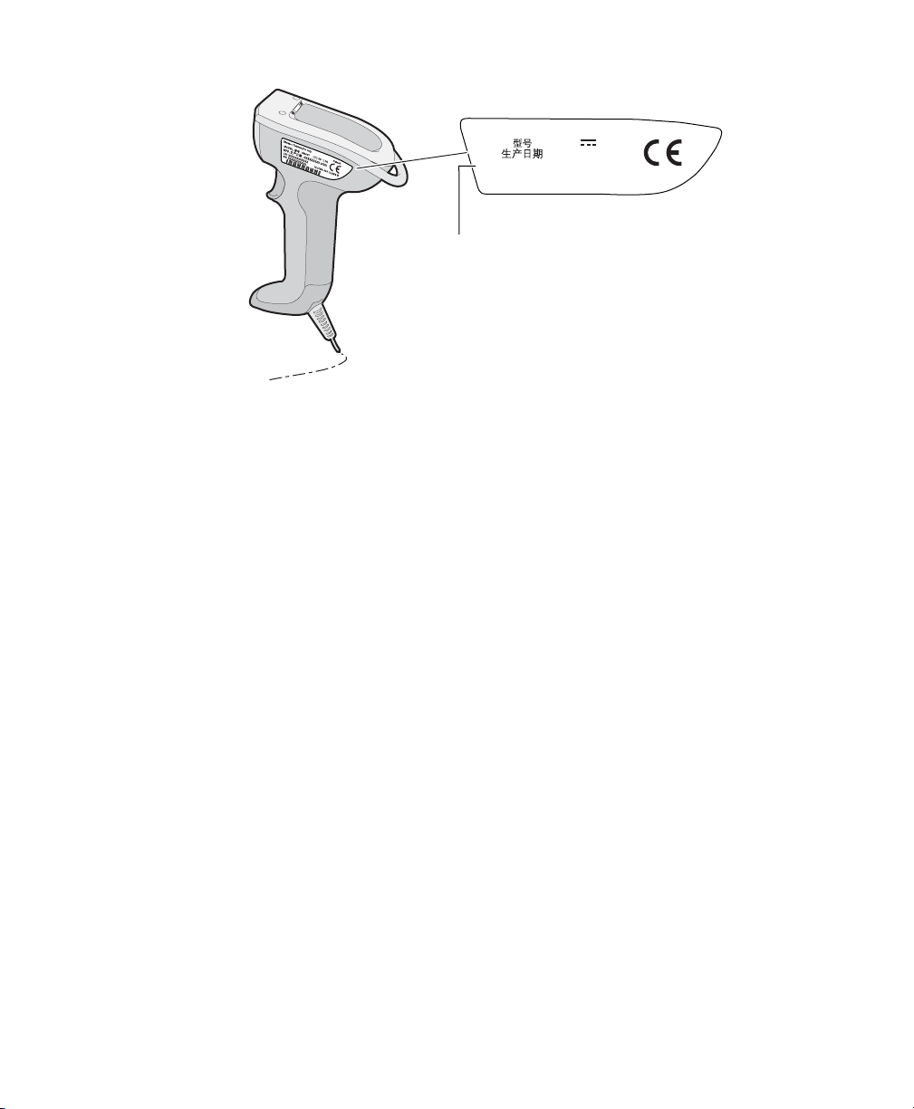
SR61T Scan Engine Option: The scan engine option of your SR61T can be found
SR61T2D-XXX
IC:ICES-003 CLASS B
SN: XXXXXXXXXXX
CN: SR61T2D-XXX
Intermec Technologies Corp.
XXXXXXXX
MODEL, : SR61T
Patent
MFD, :
XXXXXXXXX 20XX
5V 1,7A
in the first part of the configuration number. In this illustration, the scan
engine option is SR61T2D for 2D linear imager.
Supported Interfaces
The SR61T supports the following interfaces:
• USB—keyboard HID and virtual COM
Chapter 1 — Introducing the SR61T
• Standard RS-232
• Keyboard wedge/Y-Cable
• Wand emulation
Powering the SR61T
The SR61T is powered through the accessory cable that connects it to
the host computer. Depending on your connection, power for the
SR61T comes from either the host computer or an external power
supply connected to the interface cable.
SR61T Tethered Scanner User’s Guide 3
Page 16

Chapter 1 — Introducing the SR61T
Connecting the Interface Cable
The cable you use depends on the interface and host device. However
all cables are connected to the scanner in the same way.
1 Insert cable. Press firmly until inserted all the way.
2 Tighten the screw on the cable to secure it.
Removing the Interface Cable
To remove the cable follow these steps:
1 Loosen the screw on the cable.
2 Pull out the cable.
4 SR61T Tethered Scanner User’s Guide
Page 17

Accessories
There are several different accessories available. Here you will find a
list of required and optional accessories.
Required Accessories
You will need one or more of the following cables for your SR61T.
SR61T Cable List
Cable Part Number
USB cable 236-240-xxx
USB cable with power jack 236-241-xxx
RS-232 cable (6.5 feet) 236-184-xxx
RS-232 cable (12 feet) 236-197-xxx
RS-232 cable (6.5 feet) with power jack 236-185-xxx
RS-232 cable (12 feet) with power jack 236-198-xxx
Keyboard wedge cable 236-186-xxx
Keyboard wedge cable with power jack 236-187-xxx
Keyboard wedge Y-Cable 236-214-xxx
Wand cable (10 pin industry standard) 236-189-xxx
Wand cable (10 pin) 236-188-xxx
Wand cable (9 pin) 236-190-xxx
Download cable 236-239-xxx
Universal Intermec power supply 5V 851-089-205
Chapter 1 — Introducing the SR61T
Note: A power cord is also needed to plug in the power supply. The
power cord needed depends on your country and is sold seperately.
SR61T Tethered Scanner User’s Guide 5
Page 18

Chapter 1 — Introducing the SR61T
Optional Accessories
The following accessories are optional.
Desktop Stand
SR61T Desktop Stand (P/N 203-878-xxx): The desktop stand provides you with
a convenient way to store the SR61T when you are not using it.
Hands-Free Stand
SR61T Hands-Free Stand (P/N 203-877-xxx): The hands-free stand provides
you with a convenient way to store the SR61T when you are not using it or scan
items without having to hold your scanner.
6 SR61T Tethered Scanner User’s Guide
Page 19

Chapter 1 — Introducing the SR61T
Wall or Vehicle Mount Holder
SR61T Wall or Vehicle Mount Holder (P/N 203-876-xxx): The wall or vehicle
mount holder provides you with a convenient way to store the SR61T when you
are not using it. You can either attach the holder to a wall with screws or attach
the holder to a vehicle with tie-wraps.
SR61T Tethered Scanner User’s Guide 7
Page 20

Chapter 1 — Introducing the SR61T
8 SR61T Tethered Scanner User’s Guide
Page 21

2
Scanning With the SR61T
This chapter explains how to scan bar codes and includes
the following sections:
• Understanding the SR61T Behavior
• Scanning Bar Codes
9
Page 22

Chapter 2 — Scanning With the SR61T
Understanding the SR61T Behavior
The SR61T uses lights, beeps and vibrations to indicate if a bar code
has been successfully decoded. The status light and beeps described in
this section are new and do not correspond to the legacy SR61T
models (SR61TV, SR61TA, SR61TL or SR61TE).
Note: If you prefer to use the legacy beep and LED mode you can
activate the legacy mode using EasySet. For information on using
EasySet see Chapter 4, “Configuring the SR61T” on page 31.
Understanding the Status Light
The status light on the SR61T flashes red or green depending on the
status of the scanner.
Default Status Light Description
Light State What it Means
Series of green
flashes (USB
interface only)
Green light on for 2
seconds
Green light flashes 2
times
Red light on for 2
seconds
Power-up
At power-up the status light flashes to indicate the
activated USB interface:
—1 flash = Keyboard HID
—3 flashes = Virtual COM
The status light only flashes at power up for a USB
interface.
The scanner successfully decoded a bar code and sent
the data to the host device.
A configuration bar code was successfully read.
Transmission error
OR
Configuration bar code was not accepted
10 SR61T Tethered Scanner User’s Guide
Page 23

Understanding the Beeps
The SR61T beeps to give you audio feedback when performing some
functions. For example, you hear a beep each time you scan a valid bar
code.
Default SR61T Beep Descriptions
Beep Sequence What it Means
Two beeps Power-up
Single beep The scanner successfully scanned a bar code.
Two fast beeps
Six very fast beeps Transmission error
Stacked Code Crackle
When using SR61TL (laser scanner) by default the scanner makes a
crackle noise when reading stacked codes (such as PDF417). For more
information see EasySet.
Chapter 2 — Scanning With the SR61T
Configuration bar code successfully scanned
OR
Configuration bar code was not accepted
Note: You can modify many of the default settings for the light, beeps
and crackle using EasySet version 5.6.4.0 or higher. EasySet is
available on the Intermec website at www.intermec.com/EasySet.
SR61T Tethered Scanner User’s Guide 11
Page 24

Chapter 2 — Scanning With the SR61T
Using Vibrate Alert
You can configure the SR61T to vibrate when it successfully decodes a
bar code. This feature can be useful in these situations:
• You are in a noisy environment, such as a busy warehouse, where it
can be difficult to hear the beep.
• You are working in a quiet environment, such as a library, where
you do not want to make a lot of noise.
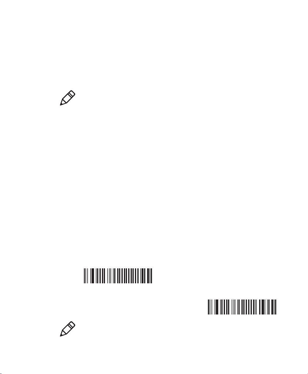
To turn on vibrate alert
• Scan this bar code:
Turn On Vibrate Alert
To turn off vibrate alert
• Scan this bar code:
Turn Off Vibrate Alert
12 SR61T Tethered Scanner User’s Guide
Page 25

Scanning Bar Codes
For the SR61TL, SR61TXR, SR61THP and SR61T2D do not look
directly into the window area or at a reflection of the laser beam
or laser aiming beam while scanning. Long-term exposure to the
laser beam can damage your vision.
The SR61T contains either a 1D linear imager (SR61T1D), 2D area
imager (SR61T2D or SR61THP), laser scan engine (SR61TL), or nearfar range area imager (SR61TXR) to scan bar code data. The type of
scan engine you are using and the type of bar code you are decoding
determines the way you scan the bar code.
When you unpack the SR61T, these bar code symbologies are enabled:
• Code 39
• Code 128 / GS1-128
• EAN/UPC
• PDF417 (SR61TL, SR61T2D, SR61THP and SR61TXR only)
Chapter 2 — Scanning With the SR61T
• DataMatrix (SR61T2D, SR61THP and SR61TXR only)
If you are using bar code labels that are encoded in a different
symbology, you need to enable the symbology on your SR61T. Use
EasySet version 5.6.4.0 or later to enable and disable symbologies for
your scanner. EasySet is available on the Intermec web site at
www.intermec.com/EasySet.
SR61T Tethered Scanner User’s Guide 13
Page 26

Chapter 2 — Scanning With the SR61T
ABCD
ABCD
To scan a bar code label with a laser scanner or 1D linear imager
1 Point the SR61T at the bar code label and hold the SR61T at a
slight angle 15 to 25 cm (6 to 10 in) from the label.
2 Pull the trigger, and direct the red beam so that it falls across all
bars in the bar code label.
Use this test bar code:
Code 39 Test Bar Code
*123456*
*123456*
Tip: Depending on your screen resolution, you can scan bar codes
displayed on your computer screen except when scanning with the
SR61TL (laser imager). Print out and scan bar codes with the
SR61TL (laser imager).
When the SR61T successfully reads a bar code label, the SR61T
beeps one time, the status light briefly turns green, and the
scanner beam turns off. If Vibrate Alert is enabled, the SR61T
briefly vibrates.
14 SR61T Tethered Scanner User’s Guide
3 Release the trigger.
ABCD
Status light
Scanning Bar Codes: The aiming and scanner beams that you see depend
on which SR61T model you are using.
Page 27
Chapter 2 — Scanning With the SR61T
24°
15°
30°
20°
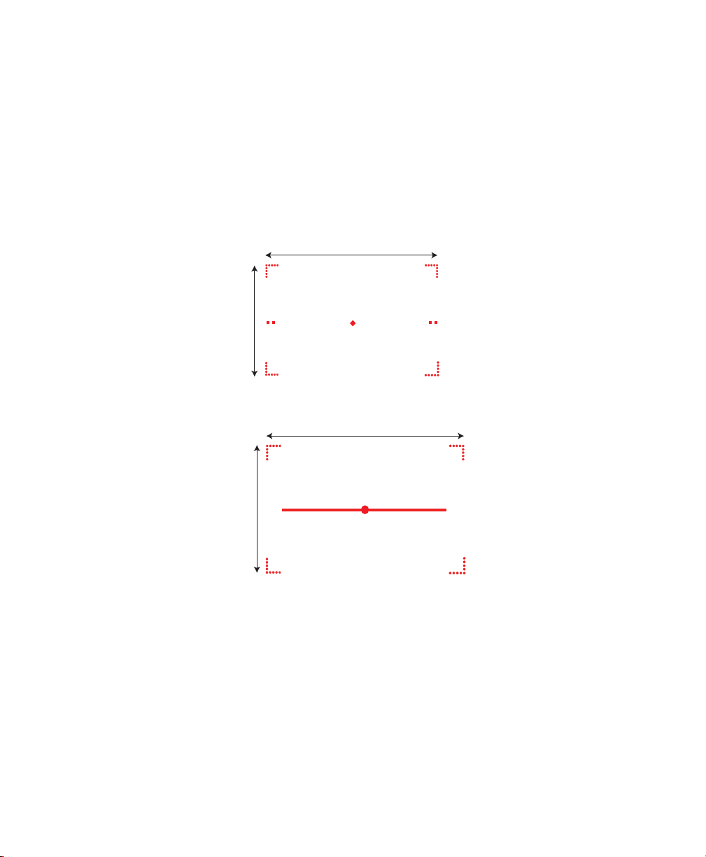
To scan omni-directionally with the 2D, 2D high performance or nearfar range area imager
1 Point the scanner window at the bar code label and hold the
SR61T steady a few inches from the label.
2 Pull the trigger.
• If you are scanning with one of the 2D imagers, use the laser
framing to position the imager over the bar code or area to
capture.
SR61T2D Laser Framing
SR61THP Laser Framing
• If you are scanning with a near-far range area imager at a near
distance (< 30 cm / 11.8 in) , position the red aiming beam just
to the right of the center of the bar code label.
SR61T Tethered Scanner User’s Guide 15
Page 28

Chapter 2 — Scanning With the SR61T
bar code
center axis
SR61TXR Aiming Beam
Note: When scanning from a far distant (> 30 cm / 11.8 in)
position the red aiming beam closer to the center of the bar
code.
3 When the SR61T successfully reads a bar code label, the SR61T
beeps one time, the status light briefly turns green, and the
scanner lighting turns off. If Vibrate Alert is enabled, the SR61T
briefly vibrates.
4 Release the trigger.
Hands-Free Scanning
The SR61T is a hand-held scanner however using the Hands-Free
Stand (P/N 203-877-xxx) you can also set up your scanner for
scanning items without having to hold your scanner in your hand (see
“Hands-Free Stand” on page 6. For hands-free scanning you will
need to use EasySet to change the default trigger mode. See EasySet
version 5.6.4.0 or higher for more information.
16 SR61T Tethered Scanner User’s Guide
Page 29

3
SR61T Interfaces
This chapter explains the different interfaces available with
the SR61T:
• USB Interface
• RS-232 Interface
• Keyboard Wedge/Y-Cable Interface
• Wand Emulation Interface
17
Page 30

Chapter 3 — SR61T Interfaces
Standard USB cable
USB cable with power jack
USB Interface
The SR61T can be connected to a USB host using one of the USB
cables. The SR61T is USB 2.0 and operates at full speed. Power is
provided either by the host or by the external power supply connected
to the USB cable. See the “Required Accessories” on page 5 for a list
of part numbers for the different cables.
Connecting a USB Cable
To connect with a USB cable
1 Turn off your host device.
2 Connect the USB cable to your SR61T and to the host.
3 Connect the power supply to the cable and an AC power outlet if
you are using the externally powered USB cable.
18 SR61T Tethered Scanner User’s Guide
Page 31

4 Turn on your host device.
Note: If you are using a non-powered USB cable, you may get a
message that the host does not provide enough power. For
example when you connect the USB cable to a keyboard hub or
if there are other USB devices connected. In this case use a
different hub or disconnect other USB devices. Otherwise use a
powered USB cable.
5 If necessary, use the configuration bar codes in the next section to
configure your SR61T for an International keyboard. The default
keyboard is North America.
Setting up the USB Interface
This section provides configuration bar codes for a basic USB
interface setup. All bar codes marked with (*) indicate the default
value. For more configuration options see Chapter 4, "Configuring
the SR61T” on page 31.
International Keyboard
By default the SR61T uses the keyboard HID USB cable mode. Use
these configuration bar codes to select the keyboard for your country.
For additional keyboards see EasySet.
Chapter 3 — SR61T Interfaces
North American Windows (*)
French Windows
French Canadian Windows 95/98
French Canadian Windows XP/2000
SR61T Tethered Scanner User’s Guide 19
Page 32

Chapter 3 — SR61T Interfaces
German Windows
Italian Windows
UK English Windows
Spanish Windows
Swedish Windows
Japanese Windows
Brazilian Portuguese Windows
Czech Republic Windows
Slovakian Windows
Hungarian 101-Key
20 SR61T Tethered Scanner User’s Guide
Page 33

Chapter 3 — SR61T Interfaces
USB Cable Mode
By default the USB cable mode is set to keyboard HID. However you
can also set up your scanner to use the virtual COM USB cable mode.
USB Keyboard HID (*)
USB Virtual COM
For a first time setup when using the virtual COM USB cable mode
you will need to download and install the driver (IntermecVCOM.inf).
You can download the driver from Knowledge Central on the
Intermec website.
To download the USB virtual COM driver:
1 Go to http://intermec.custhelp.com.
2 Click on the Find Answers tab.
3 Type “12516” in the Search by Keyword field and click on the
Search button or press Enter on your keyboard.
4 Open the Technical Bulletin and download the
IntermecVCOM.ZIP file to your PC. Extract the file to your PC.
When you connect your scanner in virtual COM USB cable mode for
the first time you will be prompted to install the driver.
SR61T Tethered Scanner User’s Guide 21
Page 34

Chapter 3 — SR61T Interfaces
To install the USB driver (IntermecVCOM.inf file)
1 Windows informs you that it has found new hardware. Select No,
not at this time then click Next.
2 On the next screen, select Install from a list or specific location
(Advanced). Click Next.
22 SR61T Tethered Scanner User’s Guide
Page 35

Chapter 3 — SR61T Interfaces
3 Use the Browse button to find the IntermecVCOM.inf file. Click
Next.
4 Windows informs you that this software has not passed Windows
testing. Click Continue Anyway.
5 Click Finish and the install is complete.
To test that the install is successful, press the trigger. If the scanner
turns on (lighting on) the install is successful.
SR61T Tethered Scanner User’s Guide 23
Page 36

Chapter 3 — SR61T Interfaces
RS-232 Interface
The SR61T can be connected to a host using one of the RS-232 cables.
Power is provided either by the host or by the external power supply
connected to the RS-232 cable. See the “Required Accessories” on
page 5 for a list of part numbers for the different cables.
Connecting an RS-232 Cable
To connect with an RS-232 cable
1 Turn off your host device.
2 Connect the RS-232 cable to your SR61T and the host.
Standard RS-232 cable
RS-232 cable with power jack
3 Connect the power supply to the cable and an AC power outlet if
you are using the externally powered RS-232 cable.
24 SR61T Tethered Scanner User’s Guide
Page 37

4 Turn on the host device.
5 If necessary, use the configuration bar codes in the next section to
configure your SR61T serial parameters to match the PC.
The default serial parameters for the SR61T are:
Serial Parameter Default Setting
Baud rate 57600
Data bits 8
Parity None
Stop bits 1
Setting up the RS-232 Interface
This section provides configuration bar codes for a basic setup. All bar
codes marked with (*) indicate the default value. For more
configuration options see Chapter 4, "Configuring the SR61T” on
page 31.
Baud Rate
38400
Chapter 3 — SR61T Interfaces
57600 (*)
115200
128000
230400
SR61T Tethered Scanner User’s Guide 25
Page 38

Chapter 3 — SR61T Interfaces
460800
Data Bits
7
Parity
None (*)
256000
8 (*)
Even
Odd
Stop Bits
1 (*)
26 SR61T Tethered Scanner User’s Guide
2
Page 39

Keyboard Wedge/Y-Cable Interface
Keyboard wedge cable
Keyboard wedge with power jack
The SR61T can be connected to a host using a keyboard wedge or Ycable. Power is provided either by the host or by the external power
supply connected to the cable. See the “Required Accessories” on
page 5 for a list of part numbers for the different cables
Connecting a Keyboard Wedge or Y-Cable
To connect with a keyboard wedge cable
1 Turn off your host device.
2 Connect the keyboard wedge cable to your SR61T and the host.
Chapter 3 — SR61T Interfaces
3 Connect the power supply to the cable and an AC power outlet if
you are using the externally powered keyboard wedge cable.
SR61T Tethered Scanner User’s Guide 27
Page 40

Chapter 3 — SR61T Interfaces
Y-cable with optional power supply
4 Turn on your host device.
5 If necessary, configure your SR61T for an International keyboard
(see “International Keyboard” on page 19). The default
keyboard is North America.
To connect with a Y-cable
1 Turn off your host device.
2 Connect the Y-cable to your SR61T.
3 Connect one end of the Y-cable to your host device and the other
end to a PS2 keyboard. If your host device does not provide
enough power, connect the power supply to the Y-cable and an AC
power outlet.
4 Turn on your host device.
5 If necessary, configure your SR61T for an International keyboard
(see “International Keyboard” on page 19). The default
keyboard is North America.
28 SR61T Tethered Scanner User’s Guide
Page 41
Wand Emulation Interface
The SR61T can be connected to a host using a wand emulation cable.
See the “Required Accessories” on page 5 for a list of part numbers
for the different cables. The type of cable depends on the host device
or intermec computer your are using. No power supply is necessary.
Note: You can connect the following Intermec computers using a
wand emulation cable: 2420, 2425, 2435, 2455, 2475, 2480, 2481,
2485, 2486.
Connecting a Wand Emulation Cable
To create a wand emulation connection
1 Turn off your host device or Intermec computer.
2 Connect the wand emulation cable to your SR61T and the host or
Intermec computer.
3 If necessary, use the configuration bar codes in the next section to
configure your SR61T for wand emulation interface.
Chapter 3 — SR61T Interfaces
Setting up the Wand Emulation Interface
This section provides configuration bar codes for a basic setup. All bar
codes marked with (*) indicate the default value. For more
configuration options see Chapter 4, "Configuring the SR61T” on
page 31.
Logical Signal State During Transmission
Bar = 0, Space = 1 (*)
Bar = 1, Space = 0
Note: When using a wand emulation connection the postamble and
preamble are not available.
SR61T Tethered Scanner User’s Guide 29
0
Page 42

Chapter 3 — SR61T Interfaces
30 SR61T Tethered Scanner User’s Guide
Page 43

4
Configuring the SR61T
This chapter provides some basic configuration bar codes
and information on how to configure the SR61T using the
EasySet configuration application. This chapter includes:
• Basic Setup with Configuration Bar Codes
• Configuring Your Scanner with EasySet
31
Page 44

Chapter 4 — Configuring the SR61T
Basic Setup with Configuration Bar Codes
This chapter provides you with configuration bar codes for a basic
setup. For more configuration options, use EasySet (see
“Configuring Your Scanner with EasySet” on page 33).
Resetting Your Scanner
To reset your scanner, read the reset factory defaults configuration
bar code.
Reset factory defaults
Configuring Predefined Imager Modes
When using an SR61T2D, SR61THP or SR61TXR, you can configure
predefined imager modes according to the types of bar codes you
want to read. Use the following configuration bar codes to enable one
of the predefined imager modes.
1D bar codes only
Standard 1D and 2D bar codes
Configuring the Postamble
The default postamble is <CR> <LF>. For certain applications or
when using USB Keyboard HID you may need to change this setting.
Use the following configuration bar codes to change the default
postamble in your scanner.
Carriage Return + Line Feed (*)
32 SR61T Tethered Scanner User’s Guide
Page 45

Chapter 4 — Configuring the SR61T
Carriage Return
Configuring Your Scanner with EasySet
EasySet is an Intermec configuration application that provides you
with two ways to configure your scanner.
• Online setup—send configuration commands from EasySet
directly to the product.
• Offline setup—send configuration commands to a bar code setup
sheet, print the setup sheet and use a connected scanner to scan
the bar codes.
None
Enter
EasySet is available on the Intermec website at www.intermec.com/
EasySet. Simply download and install.
Online Setup with EasySet
Online setup with EasySet is only available if you are using an RS-232
cable or a USB cable.
To configure your scanner online by sending commands from EasySet
1 Connect the scanner to a host PC using an RS-232 or USB cable
and set connection parameters if necessary.
2 Start EasySet. The first time you start EasySet, the Select product
dialog box appears.
If the Select product dialog box does not appear, choose Product >
Select or click on the product icon in the upper left corner.
3 Select your product.
SR61T Tethered Scanner User’s Guide 33
Page 46

Chapter 4 — Configuring the SR61T
4 Select Communication > Select Communication Interface. The
Communication Interface dialog box appears.
5 Select the communication interface that you are using for your
scanner and click OK.
6 For RS-232 or USB Virtual Com interface: The Connection
Parameters dialog box appears. Select the COM port then click
Apply.
Note: You can find the COM port by opening the Windows
Device Manager (Open the Windows Control Panel and click
on System. Click on the Hardware tab and then click on the
Device Manager button.). The Intermec Virtual COM port is
listed under Ports (COM & LPT).
For USB Keyboard HID interface: The Online setup diaglog box
appears. Select your device and click OK.
7 EasySet connects to your scanner and retrieves the current
configuration. These configurations are indicated with a blue
check mark or blue text. Open the folders to find the
configuration commands needed. Double click each command to
send it to the scanner.
Note: The scanner does not beep when you send configuration
commands online from EasySet.
34 SR61T Tethered Scanner User’s Guide
Page 47

Offline Setup with EasySet
To configure your scanner offline by scanning bar codes
1 Start EasySet. The first time you start EasySet, the Select product
dialog box appears.
If the Select product dialog box does not appear, choose Product >
Select or click on the product icon in the upper left corner.
2 Select your product.
3 Open the folders to find the configuration commands needed.
Double-click each command to send each command to the setup
sheet.
4 Click on the Word icon to export the setup sheet to Microsoft
Word. Print out the setup sheet and scan the commands.
Chapter 4 — Configuring the SR61T
SR61T Tethered Scanner User’s Guide 35
Page 48

Chapter 4 — Configuring the SR61T
36 SR61T Tethered Scanner User’s Guide
Page 49

5
Troubleshooting and
Maintaining the SR61T
Use this chapter to solve problems you may have while
using the SR61T. This chapter contains these topics:
• Troubleshooting the SR61T
• Maintaining the SR61T
37
Page 50

Chapter 5 — Troubleshooting and Maintaining the SR61T
Troubleshooting the SR61T
If you have problems using the SR61T, use this chapter to find a
possible solution.
Calling Product Support
To talk to an Intermec Product Support representative:
• In the U.S.A. and Canada, call 1-800-755-5505
• Outside the U.S.A. and Canada, contact your local Intermec
representative. For help, go to www.intermec.com > About Us >
Contact Us.
Before you call Intermec Product Support, make sure you have the
following information:
• SR61T firmware version
• SR61T decode version
• SR61T sub-system version
To get the firmware version, decode version, and sub-system version
1 Run an application that can accept bar code information from the
SR61T:
• If you are using a USB Keyboard HID or keyboard wedge
interface, use Microsoft® Notepad.
• If you are using an RS-232 or USB Virtual Com interface, use
the EasySet ISCP Terminal window. For help, see the EasySet
software.
2 Scan one of these bar codes:
Get firmware version
Get decode version
38 SR61T Tethered Scanner User’s Guide
Page 51

Chapter 5 — Troubleshooting and Maintaining the SR61T
Get sub-system version
Problems and Possible Solutions
Use this section to find possible solutions to problems you may have.
Problems and Possible Solutions
Problem Possible Solution
You pull the trigger, but
nothing happens.
You pull the trigger, the
red scanning beam
turns on, but you
cannot successfully scan
a bar code.
The SR61T receives power from either a host or an
external power supply through an accessory cable.
Make sure:
• You are using the appropriate cable. For more
information, see “Required Accessories” on
page 5.
• The cable is connected to the appropriate port
on the host computer.
• The universal power supply (if necessary) is
properly plugged in.
Try these possible solutions:
• Make sure that the SR61T is configured for the
symbology you are scanning.
• Make sure that the SR61T is at the appropriate
scanning distance from the bar code. Move the
SR61T closer and farther away to find the
appropriate distance.
• Make sure that the SR61T is configured for the
type (1D, 2D, etc.) of bar code you are scanning.
• The bar code you are trying to scan may be
poorly printed or too small. Scan a known good
bar code to make sure that the SR61T is
working properly.
For more information, see “Scanning Bar Codes”
on page 13.
SR61T Tethered Scanner User’s Guide 39
Page 52

Chapter 5 — Troubleshooting and Maintaining the SR61T
Problems and Possible Solutions (continued)
Problem Possible Solution
You scan a bar code and
the status light turns
on, but the SR61T does
not beep.
The beep duration, volume, frequency, and
number may be configured so the SR61T does not
beep. To reset the SR61T, scan this bar code:
Reset factory defaults
You scan a
configuration bar code
and the SR61T beeps six
very fast beeps.
You scan a bar code, the
SR61T beeps once, and
the status light blinks
green once, but the data
is not transmitted to the
host computer.
You cannot scan the
Firmware upgrade bar
code on your computer
screen.
The SR61T does not recognize or support the
configuration bar code you scanned.
Try these possible solutions:
• Make sure that your data collection application
is set up to receive data from the SR61T.
• If you are using an RS-232 cable, make sure that
the serial parameters on the SR61T match the
serial parameters of the host computer. The
default serial parameters for the SR61T are:
57600 baud, 8 data bits, no parity, and 1 stop
bit.
Print out this bar code and scan it:
Firmware upgrade
40 SR61T Tethered Scanner User’s Guide
Page 53

Chapter 5 — Troubleshooting and Maintaining the SR61T
Maintaining the SR61T
To keep your SR61T in good working order, you may need to upgrade
the SR61T firmware and clean the scanner window.
Upgrading the SR61T
You may need to upgrade the SR61T firmware if there is an update
that incorporates changes to a feature or adds functionality to the
scanner. When you upgrade your scanner the current settings are
erased and replaced with the default settings. The process of
upgrading the SR61T takes about 10 minutes to complete.
To upgrade the SR61T you need:
• An RS-232, USB, or download cable. For more information on
cables, see “Required Accessories” on page 5.
• Minimum PC operating system requirements are Microsoft®
Windows® XP with SP2 or Microsoft Windows 2000 with SP4 or
higher versions.
• EasySet version 5.6.4.0 or later with WinFlash version 3.1.1.1 or
later.
• The firmware update file (.bin).
Note: Before you start the upgrade process, make sure that you are not
using the selected COM port for any other application or you receive
an error and cannot use the COM port.
To upgrade the SR61T firmware
1 Download the latest SR61T firmware update package from the
Intermec web site at www.intermec.com.
a Go to Support > Downloads.
b From the Product Category drop-down list, choose Bar Code
Scanners.
c From the Product Family drop-down list, choose Tethered.
d From the Product drop-down list, choose SR61T Hand Held
Scanner and click Submit.
SR61T Tethered Scanner User’s Guide 41
Page 54

Chapter 5 — Troubleshooting and Maintaining the SR61T
e Click the link to download the firmware upgrade package and
save it to your PC.
f Unzip the .zip file.
2 Connect your SR61T to a host PC with the appropriate cable
.
Note: If using a USB cable, you must use the USB Virtual Com
USB cable mode. See “USB Cable Mode” on page 21.
3 Scan the Reset Factory Defaults bar code:
Reset factory defaults
4 Start EasySet version 5.6.4.0 or later.
5 From the Tools menu, select Upgrade product firmware to start
WinFlash version 3.1.1.1 or later.
6 If WinFlash is not already installed you will be asked to install it.
Click Yes and following the installation instructions. After
installing Winflash, start WinFlash from the Tools menu, select
Upgrade product firmware.
42 SR61T Tethered Scanner User’s Guide
Page 55

Chapter 5 — Troubleshooting and Maintaining the SR61T
7 Select the cable and click Next.
8 Use Browse to browse to the location of the firmware upgrade file
(.bin), select the file, and click Open. Click Next.
SR61T Tethered Scanner User’s Guide 43
Page 56

Chapter 5 — Troubleshooting and Maintaining the SR61T
9 For USB cables only, scan the Firmware upgrade bar code that
appears on the screen then click OK. For other cables, go directly
to the next step.
Note: If your scanner cannot scan the bar code on your computer
screen see “Problems and Possible Solutions” on page 39 to
find the firmware upgrade bar code. Print the page out and scan
the bar code.
10 Select the Com port and parameters (if necessary) and deselect the
Display help check box. Click Next.
Note: You can find the COM port by opening the Windows Device
Manager (Open the Windows Control Panel and click on System.
Click on the Hardware tab and then click on the Device Manager
button.). The Intermec Virtual COM port is listed under Ports
(COM & LPT).
11 Click Start download.
For RS-232 cables only, scan the Firmware upgrade bar code that
appears on the screen and click OK.
44 SR61T Tethered Scanner User’s Guide
Page 57

Chapter 5 — Troubleshooting and Maintaining the SR61T
Note: If your scanner cannot scan the bar code on your computer
screen see “Problems and Possible Solutions” on page 39 to
find the firmware upgrade bar code. Print the page out and scan
the bar code.
When the firmware download is complete, the “Operation
successful” message appears.
12 Click Finish. You have successfully upgraded your scanner
firmware.
Note: If the firmware download is not successful, you must restart the
firmware download procedure.
Scanner Recovery
If something happens to your scanner and it does not turn on despite
using the correct cables and power supply, the only way to recover the
scanner is to reinstall the firmware. This is only possible when using
the download cable (see “Required Accessories” on page 5). Follow
the instructions for upgrading the firmware in this chapter.
SR61T Tethered Scanner User’s Guide 45
Page 58

Chapter 5 — Troubleshooting and Maintaining the SR61T
Cleaning the SR61T
Clean the scanner window as often as needed for the environment in
which you are using the SR61T. To clean the scanner window, you can
use soapy water, a solution of ammonia and water, or isopropyl
alcohol.
Opening the SR61T voids the warranty and may cause damage to
the internal components.
To clean the scanner window
1 Dip a clean towel or rag in soapy water, ammonia and water
solution, or isopropyl alcohol and wring out the excess. Wipe the
scanner window. Do not allow any abrasive material to touch the
window.
2 Wipe dry with a lint-free cloth.
46 SR61T Tethered Scanner User’s Guide
Page 59

A
Specifications and Reading
Distances
This appendix contains the technical specifications and
reading distances for each scanner model.
47
Page 60

Appendix — Specifications and Reading Distances
Specifications
Use this section to find technical information about the SR61T
Physical Dimensions
Length 19.4 cm (7.6 in)
Height 13.1 cm (5.2 in)
Width 7.2 cm (2.8)
Weight 320 g (11.2 oz)
Electrical Specifications
Electrical rating x 5V, 1.7A
Typical Power Consumption
(5V power supply, ambiant lighting, continuous scanning)
SR61T1D RS-232 = 126 mA
USB = 124 mA
SR61TL RS-232 = 80 mA
USB = 89 mA
SR61T2D RS-232 = 246 mA
USB = 242 mA
SR61THP RS-232 = 307 mA
USB = 298 mA
SR61TXR RS-232 = 321 mA
USB = 317 mA
Interfaces
RS-232, USB, Keyboard Wedge, Wand Emulation
48 SR61T Tethered Scanner User’s Guide
Page 61

Appendix — Specifications and Reading Distances
Temperature and Environmental Specifications
Operating -20°C to 50°C (-4°F to 122°F) @ 3.3V
Storage -40°C to 70°C (-40°F to 158°F)
Relative humidity 5 to 95% non-condensing
Shock 2000G, half sinus, 0.7 ms, 6 directions
Vibrations 8G, from 10Hz to 500Hz, 2hr/axis, 3 axes
Environmental rating IP54
Ambient light 0 to 100 000 lux
Scanning Performance
SR61T1D Scan angle: 40°
Minimum X dimension: 4 mils (0.1 mm)
SR61TL Scan angle: 38°
Min. X dimension: 4 mils
SR61T2D Scan angles: 26° horizontal, 16.8° vertical
Framing angles: 24° horizontal, 15° vertical
Min. X dimension 1D: 6 mils
Min. X dimension 2D: 7 mils
SR61THP Scan angles: 34.4° horizontal, 22.2° vertical
Framing angles: 30° horizontal, 20° vertical
Min. X dimension 1D: 4 mils
Min. X dimension 2D: 6.6 mils
SR61TXR Scan angles: 14° horizontal, 8.7° vertical, 16.4°
diagonal
Min. X dimension 1D: 3 mils
Min. X dimension 2D: 6.8 mils
Bar Code Symbologies for 2D Models (SR61T2D, SR61THP and SR61TXR)
Australian Post Infomail
Aztec Intelligent mail
BPO Interleaved 2 of 5
SR61T Tethered Scanner User’s Guide 49
Page 62

Appendix — Specifications and Reading Distances
Bar Code Symbologies for 2D Models (SR61T2D, SR61THP and SR61TXR)
Canada Post Japan Post
Codabar Matrix 2 of 5
Codablock A Maxicode
Codablock F Micro PDF417
Code 11 MSI
Code 39 Muticode
Code 93/93i PDF417
Code 128 / GS1-128 Planet
DataMatrix Plessey
Dutch Post Postnet
EAN/UPC QR Code
GS1 Composite Standard 2 of 5
GS1 DataBar Expanded Sweden Post
GS1 DataBar Limited Telepen
GS1 DataBar Omni-Directional TLC 39
GS1 DataBar Stacked PDF417
Bar Code Symbologies for 1D Models (SR61T1D and SR61TL)
Codabar GS1 DataBar Omni-Directional*
Codablock A* GS1 DataBar Stacked*
Codablock F* Interleaved 2 of 5
Code 11 Matrix 2 of 5
Code 39 Micro PDF417*
Code 93/93i MSI
Code 128 / GS1-128 PDF417*
EAN/UPC Plessey
GS1 Composite* Standard 2 of 5
GS1 DataBar Expanded* Telepen
GS1 DataBar Limited* TLC 39
* = These symbologies are only available with SR61TL (laser scanner).
50 SR61T Tethered Scanner User’s Guide
Page 63

8"
4"
6"
2"
0"
2"
4"
in
04540353025201510550
0" 18"16"14"12"10"8"6"4"2" 20"
6"
8"
10"
10"
cm
10
5
0
5
10
15
20
20
15
25
25
EAN/UPC
0.125 mm/5 mils
0.25 mm/10 mils
0.5 mm/20 mils
1 mm/40 mils
Appendix — Specifications and Reading Distances
Reading Distances
The reading distances for each scanner are typical distances measured
in an office environment (200 lux).
SR61T1D
Symbology Density Minimum Distance Maximum Distance
Code 39 0.1 mm (3.8 mils)
0.125 mm (5 mils)
0.25 mm (10 mils)
0.5 mm (20 mils)
EAN/UPC 0.33 mm (13 mils) 5.2 cm (2.05 in) 28.5 cm (11.22 in)
SR61T Tethered Scanner User’s Guide 51
1 mm (40 mils)
10 cm (3.94 in)
9 cm (3.54 in)
5.5 cm (2.17 in)
4 cm (1.57 in)
7.5 cm (2.95 in)
14 cm (5.51 in)
17.5 cm (6.89 in)
26 cm (10.24 in)
35 cm (13.78 in)
49 cm (19.29 in)
Page 64

Appendix — Specifications and Reading Distances
in
080604020 100
cm
20
10
0
40
30
50
0" 32"24"16"8" 40"
0.125 mm / 5 mils
EAN/UPC
0.5 mm / 20 mils
64"48" 56"
120 140 160
60
70
80
20
10
40
30
50
60
70
80
0
32"
24"
16"
8"
40"
64"
48"
56"
32"
24"
16"
8"
40"
64"
48"
56"
1.3 mm / 51 mils
SR61TL
Symbology Density Minimum Distance Maximum Distance
Code 39 0.125 mm (5 mils)
0.5 mm (20 mils)
1.3 mm (51 mils)
10 cm (3.94 in)
6 cm (2.36 in)
41* cm (16.14 in)
EAN/UPC 0.33 mm (13 mils) 4.5 cm (1.77 in) 49 cm (19.29 in)
*Depends on symbology length and scan angle.
52 SR61T Tethered Scanner User’s Guide
19.5 cm (7.68 in)
85 cm (33.46 in)
150 cm (59.1 in)
Page 65

SR61T2D
Appendix — Specifications and Reading Distances
0" 36"32"28"24"20"16"12"8"4"
in
10"
8"
6"
4"
2"
0"
2"
4"
6"
8"
10"
0908070605040302010
PDF417 10 mils
Data Matrix 10 mils
0.15mm/6 mils
0.25 mm / 10 mils
EAN/UPC
0.5 mm / 20 mils
25
20
15
10
5
0
5
10
15
20
25
cm
Symbology Density Minimum Distance Maximum Distance
Code 39 0.15 mm (6 mils)
0.2 mm (8 mils)
0.25 mm (10 mils)
0.5 mm (20 mils)
1 mm (40 mils)
15.5 cm (6.10 in)
11.5 cm (4.53 in)
9 cm (3.54 in)
8 cm (3.15 in)
13 cm 5.12 in)
22 cm (8.66 in)
31 cm (12.20 in)
41 cm (16.14 in)
76 cm (29.92 in)
120 cm (47.24 in)
EAN/UPC 0.33 mm (13 mils) 9 cm (3.54 in) 48 cm (18.9 in)
PDF417 0.17 mm (6.6 mils)
0.25 mm (10 mils)
0.38 (15 mils)
14.5 cm (5.71 in)
9 cm (3.54 in)
10 cm (3.94 in)
22 cm (8.66 in)
36 cm (14.17 in)
52 cm (20.47 in)
DataMatrix .025 mm (10 mils) 13 cm (5.12 in) 29 cm (11.42 in)
SR61T Tethered Scanner User’s Guide 53
Page 66

Appendix — Specifications and Reading Distances
SR61THP
0" 36"32"28"24"20"16"12"8"4"
in
10"
8"
6"
4"
2"
0"
2"
4"
6"
8"
10"
PDF417 10 mils
Data Matrix 10 mils
0908070605040302010
25
20
15
10
5
0
5
0.125mm/5 mils
10
EAN/UPC
15
0.5 mm / 20 mils
20
1 mm / 40 mils
25
cm
Symbology Density Minimum Distance Maximum Distance
Code 39 0.125 mm (5 mils)
0.5 mm (20 mils)
1mm (40 mils)
8 cm (3.15 in)
7 cm (2.76 in)
9.5 cm (3.74 in)
14 cm (5.51 in)
46 cm (18.11 in)
70 cm (27.56 in)
EAN/UPC 0.33 mm (13 mils) 6 cm (2.36 in) 32 cm (12.6 in)
PDF417 0.25 mm (10 mils)
0.38 (15 mils)
5.5 cm (2.17 in)
6.5 cm (2.56 in)
26 cm (10.24 in)
36 cm (14.17 in)
DataMatrix .025 mm (10 mils) 6 cm (2.36 in) 21 cm (8.27 in)
54 SR61T Tethered Scanner User’s Guide
Page 67

SR61TXR
32"
in
0 100
cm
160
80
0
80
160
240
240
0" 40"
80"
0.25 mm
10 mils
0.5 mm/20 mils
1 mm/40 mils
200 300 600400 700500
120" 160" 200"
64"
0"
32"
64"
800 900
240" 280" 320" 360"
96"
96"
EAN/UPC
2.5 mm/100 mils
Appendix — Specifications and Reading Distances
Symbology Density Minimum Distance Maximum Distance
Code 39 0.25 mm (10 mils)
0.5 mm (20 mils)
1 mm (40 mils)
1.3 mm (51 mils)
2.5 mm (100 mils)
16 cm (6.3 in)
16 cm (6.3 in)
* cm
* cm
* cm
110 cm (3.6 ft)
200 cm (6.6 ft)
450 cm (15 ft)
600 cm (20 ft)
870 cm (28.5 ft)
EAN 100% 0.33 mm 20 cm (7.87 in) 140 cm (4.6 ft)
DataMatrix 0.25 mm (10 mils)
1.4 mm (55 mils)
2.5 mm (100 mils)
*Depends on symbology length and scan angle.
16 cm
* cm
* cm
80 cm (2.6 ft)
400 cm (13.1 ft)
800 cm (26.2 ft)
SR61T Tethered Scanner User’s Guide 55
Page 68

Appendix — Specifications and Reading Distances
56 SR61T Tethered Scanner User’s Guide
Page 69

Page 70

Worldwide Headquarters
6001 36th Avenue West
Everett, Washington 98203
U.S.A.
tel 425.348.2600
fax 425.355.9551
www.intermec.com
© 2010 Intermec Technologies
Corporation. All rights reserved.
SR61T Tethered Scanner User’s Guide
*934-024-003*
P/N 934-024-003
 Loading...