

Page 1

Programmer’s
Reference Manual
SR60 Scanner
Page 2

Intermec Technologies Corporation
Corporate Headquarters
6001 36th Ave.W.
Everett, WA 98203
U.S.A.
www.intermec.com
The information contained herein is proprietary and is provided solely for the purpose of
allowing customers to operate and service Intermec-manufactured equipment and is not to be
released, reproduced, or used for any other purpose without written permission of Intermec.
Information and specifications contained in this document are subject to change without prior
noticed and do not represent a commitment on the part of Intermec Technologies Corporation.
© 2006 by Intermec Technologies Corporation. All rights reserved.
The word Intermec, the Intermec logo, Norand, ArciTech, Beverage Routebook, CrossBar,
dcBrowser, Duratherm, EasyADC, EasyCoder, EasySet, Fingerprint, i-gistics, INCA (under
license), Intellitag, Intellitag Gen2, JANUS, LabelShop, MobileLAN, Picolink, Ready-to-Work,
RoutePower, Sabre, ScanPlus, ShopScan, Smart Mobile Computing, SmartSystems, TE 2000,
Trakker Antares, and Vista Powered are either trademarks or registered trademarks of Intermec
Technologies Corporation.
Throughout this manual, trademarked names may be used. Rather than put a trademark (™ or ®)
symbol in every occurrence of a trademarked name, we state that we are using the names only in
an editorial fashion, and to the benefit of the trademark owner, with no intention of
infringement.
There are U.S. and foreign patents pending.
ii SR60 Scanner Programmer’s Reference Manual
Page 3

Contents
Before You Begin. . . . . . . . . . . . . . . . . . . . . . . . . . . . . . . . . . . . . . . . . . . . . . . . . . . . ix
About Cautions and Notes . . . . . . . . . . . . . . . . . . . . . . . . . . . . . . . . . . . . . ix
Global Services and Support. . . . . . . . . . . . . . . . . . . . . . . . . . . . . . . . . . . . ix
Warranty Information . . . . . . . . . . . . . . . . . . . . . . . . . . . . . . . . . ix
Web Support . . . . . . . . . . . . . . . . . . . . . . . . . . . . . . . . . . . . . . . . ix
Telephone Support . . . . . . . . . . . . . . . . . . . . . . . . . . . . . . . . . . . . x
Who Should Read This Manual . . . . . . . . . . . . . . . . . . . . . . . . . . . . . . . . . xi
Related Documents . . . . . . . . . . . . . . . . . . . . . . . . . . . . . . . . . . . . . . . . . . xi
Introduction to Programming the SR60 Scanner. . . . . . . . . . 1
1
Customizing Your Scanner’s Operation . . . . . . . . . . . . . . . . . . . . . . . . . . . . . . . . . . . . 2
How to Program the SR60 Scanner. . . . . . . . . . . . . . . . . . . . . . . . . . . . . . . . . . . . . . . 2
What Is Programming Mode?. . . . . . . . . . . . . . . . . . . . . . . . . . . . . . . . . . . . 3
What is a Programming Session? . . . . . . . . . . . . . . . . . . . . . . . . . . . . . . . . .3
Three Sample Programming Sequences . . . . . . . . . . . . . . . . . . . . . . . . . . . .4
Roadmap for Programming the Scanner. . . . . . . . . . . . . . . . . . . . . . . . . . . . 6
About the Scanner LEDs and Beeper . . . . . . . . . . . . . . . . . . . . . . . . . . . . . . . . . . . . . 6
Scanner LEDs. . . . . . . . . . . . . . . . . . . . . . . . . . . . . . . . . . . . . . . . . . . . . . . . 7
Scanner Beeper . . . . . . . . . . . . . . . . . . . . . . . . . . . . . . . . . . . . . . . . . . . . . . .7
Contents
Integrating the Scanner With Your Host System . . . . . . . . . . . . . . . . . . . . . . . . . . . . . 7
Changing the Interface Cable . . . . . . . . . . . . . . . . . . . . . . . . . . . . . . . . . . . . . . . . . . . 8
Verifying that Your Scanner Supports the Interface. . . . . . . . . . . . . . . . . . . . 8
Removing and Replacing the Scanner Interface Cable . . . . . . . . . . . . . . . . . 8
Reconfiguring the Interface Settings . . . . . . . . . . . . . . . . . . . . . . . . . . . . . . .9
Restoring Factory Default Settings . . . . . . . . . . . . . . . . . . . . . . . . . . . . . . . . . . . . . . 10
Trouble Scanning the Bar Codes in This Manual . . . . . . . . . . . . . . . . . . . . . . . . . . .11
Configuring Interface Settings . . . . . . . . . . . . . . . . . . . . . . . . . . . . . . 13
2
Wand Emulation Interface . . . . . . . . . . . . . . . . . . . . . . . . . . . . . . . . . . . . . . . . . . . . 14
Wand Emulation Settings . . . . . . . . . . . . . . . . . . . . . . . . . . . . . . . . . . . . . . . . . . . . . 14
Wand Emulation Pre/Post-Noise Settings . . . . . . . . . . . . . . . . . . . . . . . . . . 17
SR60 Scanner Programmer’s Reference Manual iii
Page 4

Contents
RS-232 Interface/WN-RS-232 (SNI) Interface . . . . . . . . . . . . . . . . . . . . . . . . . . . . 19
RS-232 Communication Parameters . . . . . . . . . . . . . . . . . . . . . . . . . . . . . . . . . . . . 19
Baud Rate . . . . . . . . . . . . . . . . . . . . . . . . . . . . . . . . . . . . . . . . . . . . . . . . . 20
Data Format Settings. . . . . . . . . . . . . . . . . . . . . . . . . . . . . . . . . . . . . . . . . 21
Handshaking. . . . . . . . . . . . . . . . . . . . . . . . . . . . . . . . . . . . . . . . . . . . . . . 23
Hardware Handshaking . . . . . . . . . . . . . . . . . . . . . . . . . . . . . . . 23
Software Handshaking . . . . . . . . . . . . . . . . . . . . . . . . . . . . . . . . 25
RS-232 ACK/NAK Options. . . . . . . . . . . . . . . . . . . . . . . . . . . . 27
RS-232 Intercharacter Delay. . . . . . . . . . . . . . . . . . . . . . . . . . . . 28
Keyboard Wedge Interface . . . . . . . . . . . . . . . . . . . . . . . . . . . . . . . . . . . . . . . . . . . . 30
PC Keyboard Interface Selection . . . . . . . . . . . . . . . . . . . . . . . . . . . . . . . . 31
Connect to a Laptop or PC and Send Control/Function Characters . . . . . 33
Caps Lock . . . . . . . . . . . . . . . . . . . . . . . . . . . . . . . . . . . . . . . . . . . . . . . . . 35
Country Mode . . . . . . . . . . . . . . . . . . . . . . . . . . . . . . . . . . . . . . . . . . . . . 36
Intercharacter Delay . . . . . . . . . . . . . . . . . . . . . . . . . . . . . . . . . . . . . . . . . 39
Quiet Interval . . . . . . . . . . . . . . . . . . . . . . . . . . . . . . . . . . . . . . . . . . . . . . 41
USB Interface . . . . . . . . . . . . . . . . . . . . . . . . . . . . . . . . . . . . . . . . . . . . . . . . . . . . . 42
Configuring Label Transmit Settings . . . . . . . . . . . . . . . . . . . . . . 47
3
When to Configure Label Transmit Settings . . . . . . . . . . . . . . . . . . . . . . . . . . . . . . 48
How to Use the Prefix, Suffix, and Label ID . . . . . . . . . . . . . . . . . . . . . . . . . . . . . . 48
Setting Global Prefix(es) . . . . . . . . . . . . . . . . . . . . . . . . . . . . . . . . . . . . . . . . . . . . . 49
Setting Global Suffix(es) . . . . . . . . . . . . . . . . . . . . . . . . . . . . . . . . . . . . . . . . . . . . . 50
Setting a Single-Character Prefix or Suffix . . . . . . . . . . . . . . . . . . . . . . . . . . . . . . . . 52
Disabling a Global Prefix or Suffix. . . . . . . . . . . . . . . . . . . . . . . . . . . . . . . . . . . . . . 53
Setting a Label ID . . . . . . . . . . . . . . . . . . . . . . . . . . . . . . . . . . . . . . . . . . . . . . . . . . 55
About Symbology-Specific Label Identifiers. . . . . . . . . . . . . . . . . . . . . . . . 55
Setting the Label ID Location . . . . . . . . . . . . . . . . . . . . . . . . . . . . . . . . . . 56
Setting a Symbology-Specific Label ID . . . . . . . . . . . . . . . . . . . . . . . . . . . 57
Selecting the Symbology . . . . . . . . . . . . . . . . . . . . . . . . . . . . . . . . . . . . . . 58
Setting a Single-Character Label ID. . . . . . . . . . . . . . . . . . . . . . . . . . . . . . 62
Disabling a Symbology-Specific Label ID . . . . . . . . . . . . . . . . . . . . . . . . . 63
iv SR60 Scanner Programmer’s Reference Manual
Page 5

Enabling and Configuring Symbologies . . . . . . . . . . . . . . . . . . .65
4
All Symbologies Supported by All Interfaces . . . . . . . . . . . . . . . . . . . . . . . . . . . . . . . 66
Enabling Symbologies. . . . . . . . . . . . . . . . . . . . . . . . . . . . . . . . . . . . . . . . . . . . . . . . 66
Code 39/PharmaCode 39 Options . . . . . . . . . . . . . . . . . . . . . . . . . . . . . . . . . . . . . . 71
About Code 39 Options. . . . . . . . . . . . . . . . . . . . . . . . . . . . . . . . . . . . . . . 71
Check Digit . . . . . . . . . . . . . . . . . . . . . . . . . . . . . . . . . . . . . . . . . 71
Start/Stop Characters . . . . . . . . . . . . . . . . . . . . . . . . . . . . . . . . . . 71
Code 39 Full ASCII. . . . . . . . . . . . . . . . . . . . . . . . . . . . . . . . . . . 71
Minimum Label Length. . . . . . . . . . . . . . . . . . . . . . . . . . . . . . . . 71
Read Verification . . . . . . . . . . . . . . . . . . . . . . . . . . . . . . . . . . . . . 71
Configuring the Code 39 Options . . . . . . . . . . . . . . . . . . . . . . . . . . . . . . . 72
Minimum Label Length. . . . . . . . . . . . . . . . . . . . . . . . . . . . . . . . 73
Read Verification . . . . . . . . . . . . . . . . . . . . . . . . . . . . . . . . . . . . . 76
About PharmaCode 39 Options . . . . . . . . . . . . . . . . . . . . . . . . . . . . . . . . .77
Transmit Check Digit . . . . . . . . . . . . . . . . . . . . . . . . . . . . . . . . . 77
Start/Stop Characters . . . . . . . . . . . . . . . . . . . . . . . . . . . . . . . . . . 77
Configuring the PharmaCode 39 Options . . . . . . . . . . . . . . . . . . . . . . . . . 77
Code 128 and UCC/EAN 128 Options . . . . . . . . . . . . . . . . . . . . . . . . . . . . . . . . . . 78
About Code 128 and UCC/EAN 128 Options. . . . . . . . . . . . . . . . . . . . . . 78
Setting Minimum Label Length. . . . . . . . . . . . . . . . . . . . . . . . . .78
Read Verification . . . . . . . . . . . . . . . . . . . . . . . . . . . . . . . . . . . . . 79
Configuring the Code 128/and UCC/EAN 128 Options. . . . . . . . . . . . . . 79
Minimum Label Length. . . . . . . . . . . . . . . . . . . . . . . . . . . . . . . . 79
Read Verification . . . . . . . . . . . . . . . . . . . . . . . . . . . . . . . . . . . . . 81
Contents
Interleaved 2 of 5 Options . . . . . . . . . . . . . . . . . . . . . . . . . . . . . . . . . . . . . . . . . . . . 82
About Interleaved 2 of 5 Options . . . . . . . . . . . . . . . . . . . . . . . . . . . . . . . .82
Check Digit . . . . . . . . . . . . . . . . . . . . . . . . . . . . . . . . . . . . . . . . . 83
Label Length Format . . . . . . . . . . . . . . . . . . . . . . . . . . . . . . . . . . 83
Read Verification . . . . . . . . . . . . . . . . . . . . . . . . . . . . . . . . . . . . . 84
Configuring the Interleaved 2 of 5 Options . . . . . . . . . . . . . . . . . . . . . . . . 84
Label Length Format . . . . . . . . . . . . . . . . . . . . . . . . . . . . . . . . . . 85
Variable Length Format . . . . . . . . . . . . . . . . . . . . . . . . . . . . . . . . 85
Fixed Length Format . . . . . . . . . . . . . . . . . . . . . . . . . . . . . . . . . .86
Read Verification . . . . . . . . . . . . . . . . . . . . . . . . . . . . . . . . . . . . . 90
Codabar Options . . . . . . . . . . . . . . . . . . . . . . . . . . . . . . . . . . . . . . . . . . . . . . . . . . .91
About Codabar Options. . . . . . . . . . . . . . . . . . . . . . . . . . . . . . . . . . . . . . . 91
Check Digit . . . . . . . . . . . . . . . . . . . . . . . . . . . . . . . . . . . . . . . . . 91
Gap Check. . . . . . . . . . . . . . . . . . . . . . . . . . . . . . . . . . . . . . . . . . 91
SR60 Scanner Programmer’s Reference Manual v
Page 6

Contents
Label Length Format . . . . . . . . . . . . . . . . . . . . . . . . . . . . . . . . . 91
Start/Stop Characters . . . . . . . . . . . . . . . . . . . . . . . . . . . . . . . . . 92
Start/Stop Match . . . . . . . . . . . . . . . . . . . . . . . . . . . . . . . . . . . . 92
Start/Stop Format . . . . . . . . . . . . . . . . . . . . . . . . . . . . . . . . . . . . 93
Read Verification . . . . . . . . . . . . . . . . . . . . . . . . . . . . . . . . . . . . 93
Configuring the Codabar Options. . . . . . . . . . . . . . . . . . . . . . . . . . . . . . . 93
Label Length Format . . . . . . . . . . . . . . . . . . . . . . . . . . . . . . . . . 94
Variable Length Format . . . . . . . . . . . . . . . . . . . . . . . . . . . . . . . 94
Fixed Length Format . . . . . . . . . . . . . . . . . . . . . . . . . . . . . . . . . 95
Read Verification . . . . . . . . . . . . . . . . . . . . . . . . . . . . . . . . . . . 100
UPC/EAN Options . . . . . . . . . . . . . . . . . . . . . . . . . . . . . . . . . . . . . . . . . . . . . . . . 101
About UPC/EAN Options . . . . . . . . . . . . . . . . . . . . . . . . . . . . . . . . . . . 101
Data Format Settings . . . . . . . . . . . . . . . . . . . . . . . . . . . . . . . . 101
UPC/EAN Expansion. . . . . . . . . . . . . . . . . . . . . . . . . . . . . . . . 101
UPC/EAN Add-ons . . . . . . . . . . . . . . . . . . . . . . . . . . . . . . . . . 101
Price/Weight Check Digit. . . . . . . . . . . . . . . . . . . . . . . . . . . . . 102
Read Verification . . . . . . . . . . . . . . . . . . . . . . . . . . . . . . . . . . . 102
Configuring the UPC/EAN Options. . . . . . . . . . . . . . . . . . . . . . . . . . . . 102
UPC Data Format Settings . . . . . . . . . . . . . . . . . . . . . . . . . . . . 102
EAN Data Format Settings . . . . . . . . . . . . . . . . . . . . . . . . . . . . 104
UPC/EAN Expansion. . . . . . . . . . . . . . . . . . . . . . . . . . . . . . . . 105
UPC/EAN Add-ons . . . . . . . . . . . . . . . . . . . . . . . . . . . . . . . . . 107
Custom Add-ons. . . . . . . . . . . . . . . . . . . . . . . . . . . . . . . . . . . . 109
Price/Weight Check Digit. . . . . . . . . . . . . . . . . . . . . . . . . . . . . 109
Read Verification . . . . . . . . . . . . . . . . . . . . . . . . . . . . . . . . . . . 110
Code 93 Options. . . . . . . . . . . . . . . . . . . . . . . . . . . . . . . . . . . . . . . . . . . . . . . . . . 112
About Code 93 Options . . . . . . . . . . . . . . . . . . . . . . . . . . . . . . . . . . . . . 112
Minimum Label Length . . . . . . . . . . . . . . . . . . . . . . . . . . . . . . 112
Read Verification . . . . . . . . . . . . . . . . . . . . . . . . . . . . . . . . . . . 112
Configuring the Code 93 Options. . . . . . . . . . . . . . . . . . . . . . . . . . . . . . 113
Minimum Label Length . . . . . . . . . . . . . . . . . . . . . . . . . . . . . . 113
Read Verification . . . . . . . . . . . . . . . . . . . . . . . . . . . . . . . . . . . 115
Standard 2 of 5/IATA Options. . . . . . . . . . . . . . . . . . . . . . . . . . . . . . . . . . . . . . . . 116
About Standard 2 of 5/IATA Options . . . . . . . . . . . . . . . . . . . . . . . . . . . 116
Check Digit . . . . . . . . . . . . . . . . . . . . . . . . . . . . . . . . . . . . . . . 117
Label Length Format . . . . . . . . . . . . . . . . . . . . . . . . . . . . . . . . 117
Read Verification . . . . . . . . . . . . . . . . . . . . . . . . . . . . . . . . . . . 118
Configuring the Standard 2 of 5/IATA Options . . . . . . . . . . . . . . . . . . . 118
Label Length Format . . . . . . . . . . . . . . . . . . . . . . . . . . . . . . . . 119
Variable Length Format . . . . . . . . . . . . . . . . . . . . . . . . . . . . . . 119
Fixed Length Format . . . . . . . . . . . . . . . . . . . . . . . . . . . . . . . . 120
Read Verification . . . . . . . . . . . . . . . . . . . . . . . . . . . . . . . . . . . 123
vi SR60 Scanner Programmer’s Reference Manual
Page 7

IATA Options . . . . . . . . . . . . . . . . . . . . . . . . . . . . . . . . . . . . . . . . . . . . . . . . . . . . . 124
MSI/Plessey Options. . . . . . . . . . . . . . . . . . . . . . . . . . . . . . . . . . . . . . . . . . . . . . . .125
About MSI/Plessey Options . . . . . . . . . . . . . . . . . . . . . . . . . . . . . . . . . . . 125
Check Digit . . . . . . . . . . . . . . . . . . . . . . . . . . . . . . . . . . . . . . . . 125
Label Length Format . . . . . . . . . . . . . . . . . . . . . . . . . . . . . . . . . 125
Read Verification . . . . . . . . . . . . . . . . . . . . . . . . . . . . . . . . . . . . 126
Configuring the MSI /Plessey Options. . . . . . . . . . . . . . . . . . . . . . . . . . .126
Label Length Format . . . . . . . . . . . . . . . . . . . . . . . . . . . . . . . . . 127
Variable Length Format . . . . . . . . . . . . . . . . . . . . . . . . . . . . . . . 127
Fixed Length Format . . . . . . . . . . . . . . . . . . . . . . . . . . . . . . . . .128
Read Verification . . . . . . . . . . . . . . . . . . . . . . . . . . . . . . . . . . . . 132
Configuring General Features . . . . . . . . . . . . . . . . . . . . . . . . . . . . . . 133
5
Configuring the Green LED Idle State . . . . . . . . . . . . . . . . . . . . . . . . . . . . . . . . . . 134
Configuring the Beeper Settings . . . . . . . . . . . . . . . . . . . . . . . . . . . . . . . . . . . . . . .134
Configuring the Marker Beam . . . . . . . . . . . . . . . . . . . . . . . . . . . . . . . . . . . . . . . . 138
Configuring the Low Power Mode . . . . . . . . . . . . . . . . . . . . . . . . . . . . . . . . . . . . . 140
Contents
Configuring the Low Power Shutdown Delay . . . . . . . . . . . . . . . . . . . . . . . . . . . . . 141
Configuring the Half-Angle . . . . . . . . . . . . . . . . . . . . . . . . . . . . . . . . . . . . . . . . . . 142
Factory Default Configuration . . . . . . . . . . . . . . . . . . . . . . . . . . . . . 145
A
Factory Default Configuration . . . . . . . . . . . . . . . . . . . . . . . . . . . . . . . . . . . . . . . . 146
Reference Information . . . . . . . . . . . . . . . . . . . . . . . . . . . . . . . . . . . . . .151
B
Sample Bar Codes. . . . . . . . . . . . . . . . . . . . . . . . . . . . . . . . . . . . . . . . . . . . . . . . . . 152
Keypad Bar Codes. . . . . . . . . . . . . . . . . . . . . . . . . . . . . . . . . . . . . . . . . . . . . . . . . . 154
RS-232 Host Commands . . . . . . . . . . . . . . . . . . . . . . . . . . . . . . . . . . . . . . . . . . . . 157
ASCII Character Set . . . . . . . . . . . . . . . . . . . . . . . . . . . . . . . . . . . . . . . . . . . . . . . . 158
Contacting Intermec Product Support . . . . . . . . . . . . . . . . . . . . . . . . . . . . . . . . . .159
SR60 Scanner Programmer’s Reference Manual vii
Page 8

Contents
viii SR60 Scanner Programmer’s Reference Manual
Page 9
Before You Begin
This section provides you with safety information, technical
support information, and sources for additional product
information.
About Cautions and Notes
Read and follow all cautions in this document before handling
and operating Intermec equipment. Equipment and data can be
damaged if you do not follow the cautions.
This section explains how to identify and understand cautions
and notes that are in this document.
A caution alerts you to an operating procedure, practice,
condition, or statement that must be strictly observed to
prevent equipment damage or destruction, or corruption or
loss of data.
Note: Notes either provide extra information about a topic or
contain special instructions for handling a particular condition or
set of circumstances.
Before You Begin
Global Services and Support
Warranty Information
To understand the warranty for your Intermec product, visit the
Intermec web site at www.intermec.com and click Service &
Support > Warranty.
Disclaimer of warranties: The sample code included in this
document is presented for reference only. The code does not
necessarily represent complete, tested programs. The code is
provided “as is with all faults.” All warranties are expressly
disclaimed, including the implied warranties of merchantability
and fitness for a particular purpose.
Web Support
Visit the Intermec web site at www.intermec.com to download
our current manuals (in PDF). To order printed versions of the
Intermec manuals, contact your local Intermec representative or
distributor.
SR60 Scanner Programmer’s Reference Manual ix
Page 10

Before You Begin
Visit the Intermec technical knowledge base (Knowledge
Central) at
intermec.custhelp.com to review technical
information or to request technical support for your Intermec
product.
Telephone Support
These services are available from Intermec Technologies
Corporation.
In the U.S.A. and
Canada call 1-800755-5505 and
Services Description
Order Intermec
products
Order Intermec
media
Order spare
parts
Te c h n i ca l
Support
Service • Get a return authorization
Service contracts • Ask about an existing
• Place an order.
• Ask about an existing
order.
Order printer labels and
ribbons.
Order spare parts. 1 or 2 and then
Talk to technical support
about your Intermec
product.
number for authorized
service center repair.
• Request an on-site repair
technician.
contract.
•Renew a contract.
• Inquire about repair
billing or other service
invoicing questions.
choose this option
1 and then choose 2
1 and then choose 1
choose 4
2 and then choose 2
2 and then choose 1
1 or 2 and then
choose 3
Outside the U.S.A. and Canada, contact your local Intermec
representative. To search for your local representative, from the
Intermec web site, click Contact.
x SR60 Scanner Programmer’s Reference Manual
Page 11

Who Should Read This Manual
This programmer’s reference manual is for the person who is
responsible for installing, programming, configuring, and
maintaining the SR60 scanner.
This document explains how to program and configure the SR60
scanner.
Before you work with the SR60, you should be familiar with the
host system to which you will connect the SR60.
Related Documents
The Intermec web site at www.intermec.com contains our
documents (as PDF files) that you can download for free.
To d ownloa d docume nts
1 Visit the Intermec web site at www.intermec.com.
2 Click Service & Support > Manuals.
3 In the Select a Product field, choose the product whose
documentation you want to download.
To order printed versions of the Intermec manuals, contact your
local Intermec representative or distributor.
Before You Begin
SR60 Scanner Programmer’s Reference Manual xi
Page 12

Before You Begin
xii SR60 Scanner Programmer’s Reference Manual
Page 13

1
Introduction to
Programming the SR60
Scanner
This chapter explains how and why you program your SR60
scanner. You will find these sections in this chapter:
• Customizing Your Scanner’s Operation
• How to Program the SR60 Scanner
• About the Scanner LEDs and Beeper
• Integrating the Scanner With Your Host System
• Changing the Interface Cable
• Restoring Factory Default Settings
• Trouble Scanning the Bar Codes in This Manual
SR60 Scanner Programmer’s Reference Manual 1
Page 14

Chapter 1 — Introduction to Programming the SR60 Scanner
Customizing Your Scanner’s Operation
You can customize your SR60 scanner’s operation using the
programming bar codes in this manual.
• You can select and configure the settings that allow
communication with your host terminal, such as setting the
RS-232 baud rate and parity for the RS-232 interface. For
help, see Chapter 2, “Configuring Interface Settings.”
• You can configure the optional prefix, suffix, and label ID to
be sent with bar code data if your scanner is configured for the
RS-232 or Keyboard Wedge interface. For help, see Chapter
3, “Configuring Label Transmit Settings.”
• You can select and configure bar code symbologies. You can
give the scanner the capability to autodiscriminate as few as
one, and as many as all available symbologies. For optimal
scanner performance, enable only those symbologies required.
You may also program the scanner with the standard options
available for the symbologies, such as check digit, minimum
label length, and fixed and variable length bar codes. For help,
see Chapter 4, “Enabling and Configuring Symbologies.”
• You can configure general features. For example, you may
adjust the beeper volume. For help, see Chapter 5,
“Configuring General Features.”
How to Program the SR60 Scanner
There are two ways for you to program the scanner:
• You can scan programming bar codes to modify the scanner’s
programmable features and options. This manual provides the
bar codes and instructions necessary to configure the features
and options. To ensure full compatibility and proper
function, use only the programming bar codes in this manual.
• You can send commands directly from the host. A limited set
of host commands are available. For help, see “RS-232 Host
Commands” on page 157.
When you program the scanner, the scanner stores the changes
until reprogrammed or returned to factory defaults.
2 SR60 Scanner Programmer’s Reference Manual
Page 15

Chapter 1 — Introduction to Programming the SR60 Scanner
What Is Programming Mode?
The scanner must be placed in Programming mode in order to
accept programming commands. You place the scanner in
Programming mode by scanning the SET bar code, which
appears first in each set of programming bar codes in this manual.
While in the Programming mode, the scanner recognizes only the
special programming bar codes contained in this manual.
To understand how the LEDs and beeper behave while the
scanner is in Programming mode, see
and Beeper” on page 6.
What is a Programming Session?
A typical programming session is conducted as follows:
1 Scan the SET bar code at the beginning of each set of
programming bar codes to place the scanner in Programming
mode. The scanner emits three beeps, indicating it has read
the bar code, and the green LED flashes on and off slowly
while the scanner remains in Programming mode. Normal
scanning functions are disabled.
2 Scan the programming bar codes that are specially encoded to
make changes. With few exceptions, the scanner emits a triple
beep each time you scan a valid bar code. Be aware of these
considerations:
“About the Scanner LEDs
• Some features, such as Minimum Label Length, require
you to select the label length by scanning a series of singledigit bar codes. A single good read beep sounds when
scanning these single digits in Programming mode. Only
the final required digit in the sequence produces a triple
beep when scanned, indicating a successfully programmed
feature.
• Not all features are available for all interfaces. The scanner
sounds an error tone if you scan programming bar codes
for features invalid to the current interface. Only features
supported by the currently active interface are
implemented.
• If you scan a bar code that changes the interface type, all
previous configuration items scanned in the programming
session are lost.
SR60 Scanner Programmer’s Reference Manual 3
Page 16

Chapter 1 — Introduction to Programming the SR60 Scanner
• When programming a feature requiring you to scan single
digits to set a multi-digit number, such as Minimum Label
Length, scanning the END bar code (or any item tag/item
value bar code) before completing all input results in an
error tone and causes the scanner to exit Programming
mode. Under these circumstances, the features you were
trying to set are discarded; any previous bar codes scanned
during the session take effect.
• Intermec recommends that you limit each programming
session to one feature at a time. If you make a mistake in
the programming sequence, it can be difficult to discover
where an error has been made if several features are
programmed at once. Additionally, it can be confusing to
determine which features may or may not have been
successfully set following such a session.
3 Scan the END bar code to save any new settings and exit
Programming mode. The scanner sounds a beep and resets
upon exiting Programming mode, and the green LED returns
to its usual state (on steady or off).
Note: If you disconnect power before you scan the END bar
code, all the new settings are discarded. On power-up, the
scanner returns to the previous settings.
4 Maintain an accurate record of all changes you make. There is
a worksheet in Appendix A, “Factory Default Configuration”
on page 145, where you can record your changes.
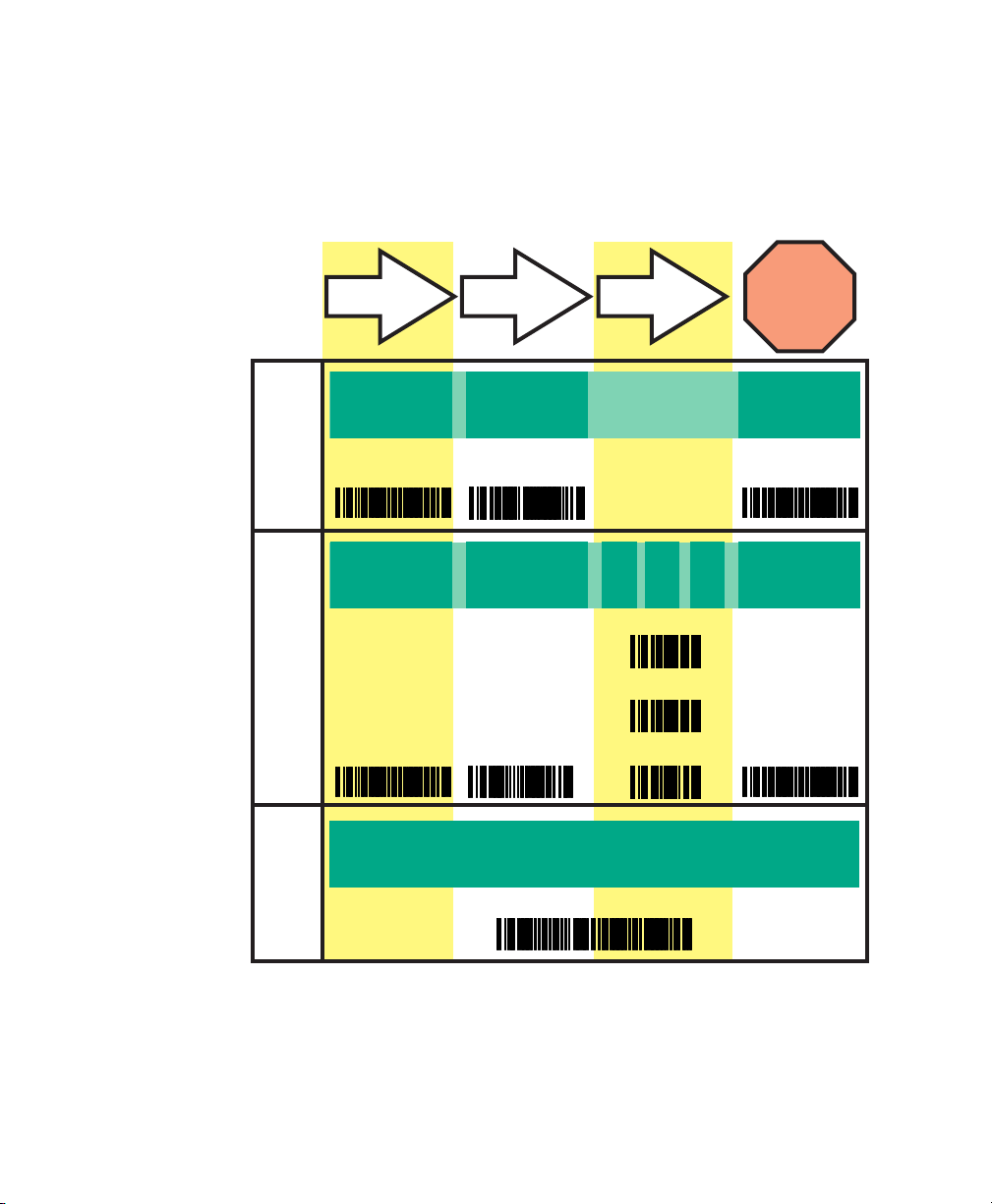
Three Sample Programming Sequences
To modify a scanner feature, you must scan the programming bar
codes in this manual in the correct sequence, depending upon the
feature being programmed. There are three programming
sequences, which are illustrated on the next page.
Sample A
Programming sample A is the most commonly used sequence and
demonstrates how three bar codes are scanned to accomplish
these tasks:
1 Enter Programming mode with the SET bar code.
2 Scan the Item Tag that enables the new feature.
4 SR60 Scanner Programmer’s Reference Manual
Page 17
Chapter 1 — Introduction to Programming the SR60 Scanner
The term Item Tag describes an assigned number encoded in
a programming bar code that selects, enables, or disables a
specific feature.
3 Exit Programming mode and reset the scanner with the END
bar code.
A
B
C
SET
1
SET
ITEM TAG ITEM VALUE END/RESET
23
ENABLE
NEW FEATURE
END
123456
0
ENABLE NEW
FEATURE
USING THE
FOLLOWING
SET END
SETTINGS...
0
8
1
ONE BAR CODE CONTAINS SET + ITEM TAG + ITEM VALUE + END
Three Sample Programming Sequences
Sample B
Programming sample B demonstrates how to enter a range value.
SR60 Scanner Programmer’s Reference Manual 5
Page 18

Chapter 1 — Introduction to Programming the SR60 Scanner
Like sample A, the scanner is placed in Programming mode and
an Item Tag is scanned. Then, a value must be entered before
ending the programming session. In the example, three digits
must be scanned from the number pad in Appendix C.
This type of format may require up to six programming bar codes
and is necessary to allow flexible programming with larger itemvalue numeric ranges.
Sample C
Programming sample C lets you scan a single, extended length
bar code. This special bar code contains all the data necessary to
enter Programming mode, set the Item Tag and Item Value, and
exit Programming mode all in one step.
Roadmap for Programming the Scanner
Follow this roadmap to program the SR60 scanner.
To program the scanner
1 Scan any feature bar codes that are unique to the interface you
are currently programming. These interface-specific
programming bar codes immediately follow each interface
selection bar code.
2 If you need to change any bar code symbologies or modify
any symbology-related features, see “Enabling Symbologies”
on page 66.
3 If you need to change or modify any other features (such as
beeper settings), see Chapter 5, “Configuring General
Features,” on page 133.
Once the necessary changes have been made, and you have
scanned the END bar code, you are ready to operate the SR60
scanner.
About the Scanner LEDs and Beeper
The scanner provides a set of indicators that verify or announce
scanner functions.
Note: The green LED and beeper are configurable features which
may have been modified or disabled. For help, see Chapter 5,
“Configuring General Features,” on page 133.
6 SR60 Scanner Programmer’s Reference Manual
Page 19

Scanner LEDs
Scanner Beeper
Chapter 1 — Introduction to Programming the SR60 Scanner
The amber Laser On LED is located on top rear of the scanner
and lights whenever laser power is on.
The green Good Read LED is located on top rear of the scanner
and flashes:
• once to indicate when a good read has occurred.
• slowly on and off to indicate the scanner is in Programming
mode.
The beeper operates differently when the scanner is in Scanning
mode and in Programming mode.
• When the scanner is in Scanning mode, the beeper sounds:
• four times at power-up.
• once following a good read.
• six rapid chirps to indicate an error (error tone).
• When the scanner is in Programming mode, the beeper
sounds:
• once when entering or exiting Programming mode.
• three times to indicate a successfully programmed feature.
• an error tone if you scan programming bar codes for
features that are not compatible with the current interface.
For example, you can set baud rate and parity only when
the current interface is RS-232.
Integrating the Scanner With Your Host System
Your scanner must be equipped with the correct hardware to
properly communicate with your host system. Contact your local
Intermec representative if you have questions about your scanner
hardware compatibility.
Intermec offers the following interface cables for the SR60
scanner:
• Wand emulation
•RS-232
SR60 Scanner Programmer’s Reference Manual 7
Page 20
Chapter 1 — Introduction to Programming the SR60 Scanner
• Keyboard wedge
•USB
Note: The part numbers for the keyboard wedge cables available
from Intermec are listed in the “PC Keyboard Interfaces and
Cables Supported ” table on page 31.
Changing the Interface Cable
If you need to move the scanner to a host terminal of a different
interface type, you simply connect the scanner to the new host
using the appropriate interface cable. The scanner automatically
changes to the interface functions specific to that cable.
Verifying that Your Scanner Supports the Interface
You must make sure that your SR60 scanner supports the
interface you want to change to. The following list indicates the
interfaces each SR60 scanner supports:
• SR60 scanner with C/N SR60AX01 supports the Wand
Emulation, RS-232, and Keyboard Wedge interfaces.
• SR60 scanner with C/N SR60AX02 supports the USB
interface.
You can find the scanner C/N on the label above the trigger.
Removing and Replacing the Scanner Interface Cable
You can change your scanner interface cable by following these
instructions.
To change the scanner interface cable
1 Loosen the screw at the bottom of the handle. This screw is
captive and does not come all the way out.
Do not try to pull the end cap off, as this may damage the
scanner.
2 Swing the forked cable retainer clear of the square hole in the
end cap and rotate away from the cable.
8 SR60 Scanner Programmer’s Reference Manual
Page 21

Chapter 1 — Introduction to Programming the SR60 Scanner
3 Holding the scanner handle and end cap together in one
hand, pull the connector out of the handle end cap to free the
interface cable.
4 Connect the new interface cable at the scanner and rotate the
forked cable retainer to secure it. Tighten the screw to 0.67 to
1.13 Nm (6 to 10 in-lb).
1
3
Removing and Replacing an Interface Cable
Reconfiguring the Interface Settings
If you change the interface cable, you may need to reconfigure
the interface settings. For help, see Chapter 2, “
Interface Settings.”
After you reconfigure the interface settings, you should scan a bar
code to verify that the scanner communicates correctly with the
new host system. For sample bar codes, see
on page 152.
2
Configuring
“Sample Bar Codes”
SR60 Scanner Programmer’s Reference Manual 9
Page 22
Chapter 1 — Introduction to Programming the SR60 Scanner
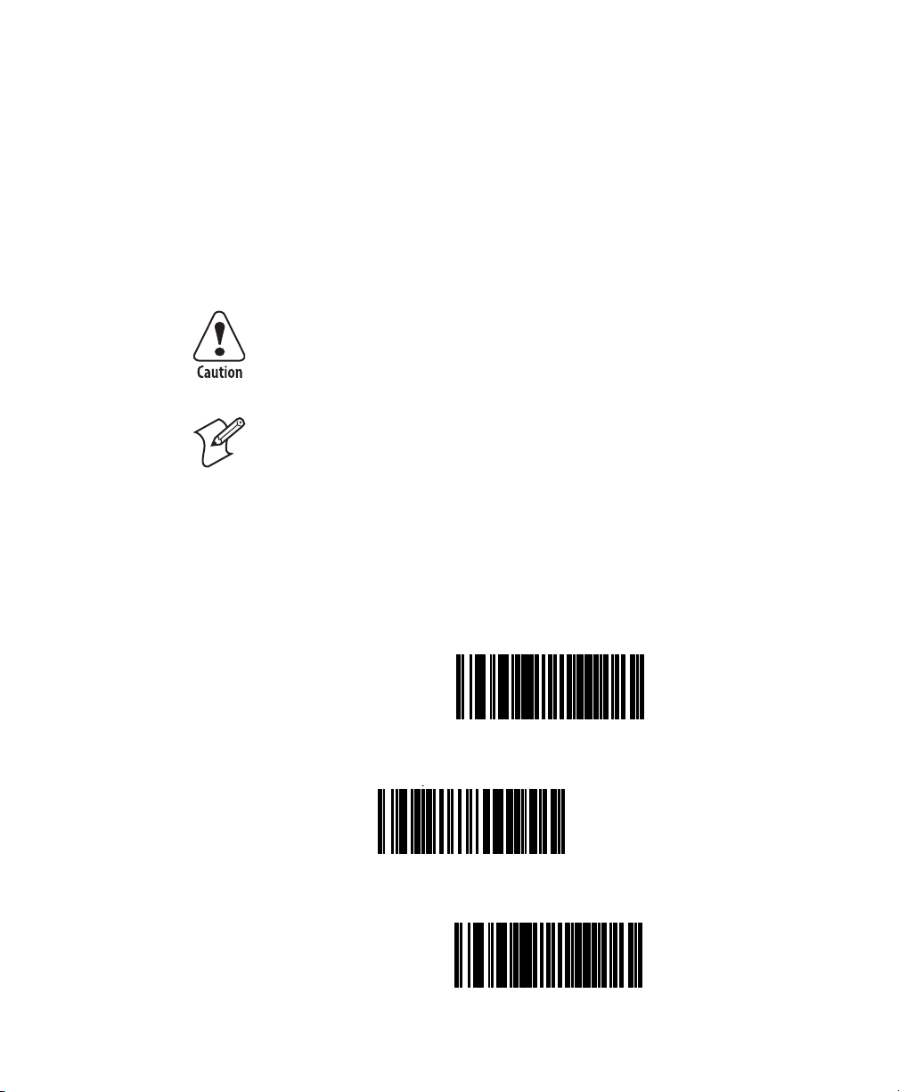
Restoring Factory Default Settings
You can restore the factory default settings at any time by
scanning the Return to Factory Default Settings bar code in this
section. This bar code is typically used to return the scanner to a
known operating state when the present programming status is
not known, faulty, or suspect.
For a list of factory default settings, see Appendix A, “Factory
Default Configuration” on page 145.
Use this bar code with caution, since it resets all changes made
during previous programming sessions.
Note: This bar code does not reset the Low Power mode. For
details, see
To restore factory defaults
1 Scan the SET bar code.
2 Scan the Return to Factory Setting bar code.
“Configuring the Low Power Mode” on page 140.
3 Scan the END bar code.
SET ------------------------- ------------------
Return to Factory Default
Settings ---------
END ------------------------------------------
10 SR60 Scanner Programmer’s Reference Manual
Page 23

Chapter 1 — Introduction to Programming the SR60 Scanner
Trouble Scanning the Bar Codes in This Manual
If you are having trouble scanning the bar codes in this manual,
make sure you follow these guidelines:
• Review the scanning instructions in the SR60 Scanner Quick
Start Guide (P/N 930-141-001) which shipped with the
scanner.
• Hold the SR60 scanner at least 1.2 m (4 ft) from the bar code
because this is a long range scanner.
• If you see more than one red marker beam, aim the center
beam on the bar code.
• Move the marker beam horizontally across the page toward
the bar code to avoid passing the marker beam over other bar
codes.
SR60 Scanner Programmer’s Reference Manual 11
Page 24

Chapter 1 — Introduction to Programming the SR60 Scanner
12 SR60 Scanner Programmer’s Reference Manual
Page 25

2
Configuring Interface
Settings
This chapter contains the programming bar codes for selecting an
interface and programming the related interface settings. You will
find these sections in this chapter:
• Wand Emulation Interface
• Wand Emulation Settings
• RS-232 Interface/WN-RS-232 (SNI) Interface
• RS-232 Communication Parameters
• Keyboard Wedge Interface
•USB Interface
SR60 Scanner Programmer’s Reference Manual 13
Page 26
Chapter 2 — Configuring Interface Settings
Wand Emulation Interface
Scan the following bar codes to enable the Wand Emulation
Interface.
SET ------------------------- ------------------
Enable Wand Emulation ---------
END ------------------------------------------
Wand Emulation Settings
Scan the following bar codes to configure the settings for the
Wand Emulation Interface.
Note: You should enable Transmit C128 Function Characters
only when Data Format is set to Transmit in Normal Format or
Transmit in Code 128 Format.
SET ------------------------- ------------------
Polarity
Space Low, Bar High ---------
14 SR60 Scanner Programmer’s Reference Manual
Page 27

Space High, Bar Low ---------
Signal Speed
Low (660 µs) ---------
High (330 µs) ---------
Data Format
Transmit in Normal
Format ---------
Chapter 2 — Configuring Interface Settings
Transmit in C39
Format ---------
Transmit in C39 Full ASCII
Format ---------
Transmit in C128
Format ---------
SR60 Scanner Programmer’s Reference Manual 15
Page 28

Chapter 2 — Configuring Interface Settings
Idle State
Low ---------
High ---------
Transmit C128 Function Characters
Enable ---------
Disable ---------
END ------------------------------------------
16 SR60 Scanner Programmer’s Reference Manual
Page 29

Chapter 2 — Configuring Interface Settings
Wand Emulation Pre/Post-Noise Settings
You can independently configure the number of noise transitions
generated prior to or following label transitions.
To disable transmitting pre-noise or post-noise transitions
1 Scan the SET bar code.
2 Scan either the Don’t Transmit Pre-Noise bar code on page 17
or the Don’t Transmit Post-Noise bar code on page 18.
3 Scan the END bar code. You have disabled noise transitions.
To set pre-noise or post-noise transitions
1 Scan the SET bar code.
2 Scan either the Set Pre-Noise Transitions bar code on page 17
or the Set Post-Noise Transitions bar code on page 18.
3 From the “Keypad Bar Codes” on page 154, scan two digits
that represent the appropriate number of noise transitions.
You can choose from one to twenty noise transitions for either
pre-noise or post-noise. For example, scan the 0 and the 3 bar
codes for three transitions.
4 Scan the END bar code.
Pre-Noise Transitions Settings
SET ----------------------- --------------------
Don’t Transmit Pre-Noise ---------
Set Pre-Noise Transitions ---------
SR60 Scanner Programmer’s Reference Manual 17
Page 30

Chapter 2 — Configuring Interface Settings
Use the bar codes in “Keypad Bar Codes” on page 154 to scan two digits
representing the number of Pre-Noise Transitions padded with leading zeros.
For example, 03 = three transitions, 08 = eight, and 15 = fifteen.
END ------------------------------------------
Post-Noise Transitions Settings
SET ------------------------- ------------------
Don’t Transmit
Post-Noise ---------
Set Post-Noise
Transitions ---------
Use the bar codes in “Keypad Bar Codes” on page 154 to scan two digits
representing the number of Post-Noise Transitions padded with leading zeros.
For example, 03 = three transitions, 08 = eight, and 15 = fifteen.
END ------------------------------------------
18 SR60 Scanner Programmer’s Reference Manual
Page 31

Chapter 2 — Configuring Interface Settings
RS-232 Interface/WN-RS-232 (SNI) Interface
Scan the following bar codes to enable either the standard
RS-232 interface or the WN-RS-232 (SNI) Interface.
SET ----------------------- --------------------
Enable Standard
RS-232 ---------
Enable WN-RS-232 ---------
END ------------------------------------------
RS-232 Communication Parameters
This section describes these RS-232 communication parameters:
•Baud Rate
• Data Format Settings: Data Bit, Parity Bit, and Stop Bit(s)
•Handshaking
• Hardware Handshaking (CTS/RTS)
• Software Handshaking (XON/XOFF)
• ACK/NAK Options
• Intercharacter Delay
SR60 Scanner Programmer’s Reference Manual 19
Page 32

Chapter 2 — Configuring Interface Settings
For help changing other settings for this interface, see:
• Chapter 3, “Configuring Label Transmit Settings,” on
page 47
• “All Symbologies Supported by All Interfaces” on page 66
• Chapter 5, “Configuring General Features,” on page 133
Baud Rate
Scan the following bar codes to select the Baud Rate. Only one
Baud Rate selection may be active at any one time. The last Baud
Rate bar code you scan during a programming session is the
setting that is stored when you scan the END bar code.
SET ------------------------- ------------------
Baud Rate = 1200 ---------
Baud Rate = 2400 ---------
Baud Rate = 4800 ---------
Baud Rate = 9600 ---------
20 SR60 Scanner Programmer’s Reference Manual
Page 33

Baud Rate = 19200 ---------
Baud Rate = 38400 ---------
END ------------------------------------------
Data Format Settings
Scan the following bar codes to select the data format
configuration needed to communicate with your system.
Chapter 2 — Configuring Interface Settings
SET ----------------------- --------------------
Data Bit
Seven ---------
Eight ---------
SR60 Scanner Programmer’s Reference Manual 21
Page 34

Chapter 2 — Configuring Interface Settings
Parity Bit
None ---------
Even ---------
Odd ---------
Mark ---------
Space ---------
Stop Bit(s)
One ---------
22 SR60 Scanner Programmer’s Reference Manual
Page 35

Two ---------
END ------------------------------------------
Handshaking
Review your system documentation to identify handshaking
requirements, and scan the following bar codes to change the
settings if required. The following descriptions briefly explain
each selection.
Hardware Handshaking
You can choose either CTS/RTS Flow Control or CTS Scan
Control:
Chapter 2 — Configuring Interface Settings
• CTS/RTS Flow Control is a type of hardware handshaking.
The scanner activates the RTS (Request to Send) line when it
is ready to send data to the host. The scanner waits for an
active Clear to Send (CTS) signal from the host before
transmitting data. If hardware control is disabled, CTS/RTS
communication does not take place. If the host deactivates the
CTS line during data transmission, the host receives
additional characters for no more than 2 ms. (The timing
varies slightly, depending on the baud rate you select.)
Data
CTS
CTS/RTS Flow Control Illustration
Label Transmission Label TransmissionXmission
Active
Disabled
Inactive
• CTS Scan Control is a type of hardware handshaking. When
scan control is enabled, label scanning is disabled until CTS is
asserted and de-asserted, as shown in the next illustration.
SR60 Scanner Programmer’s Reference Manual 23
Page 36

Chapter 2 — Configuring Interface Settings
Data
CTS
CTS Scan Control Illustration
Label 1 Label 2Label 1
Disabled until
De-assert
Handshaking controls are mutually exclusive. You cannot enable
more than one of these features at a time, because enabling
multiple controls produces unpredictable results.
Note: Each handshaking feature requires a series of bar codes in
the sequence given. That is, you must enter Programming mode
by scanning the SET bar code, scan the Step #1 bar code, scan the
Step #2 bar code, and then scan the END bar code.
Enable CTS/RTS Flow Control
Will not scan again
until toggled
Assert
SET ------------------------- ------------------
Step #1 ---------
Step #2 ---------
24 SR60 Scanner Programmer’s Reference Manual
Page 37

END ------------------------------------------
Enable CTS Scan Control
SET ----------------------- --------------------
Step #1 ---------
Step #2 ---------
Chapter 2 — Configuring Interface Settings
END ------------------------------------------
Software Handshaking
XON/XOFF is software handshaking that allows the host to
control data transmission. If the host sends an XOFF command
to the scanner, the scanner does not send the bar code data until
it receives an XON command from the host. If the host sends the
XOFF command during data transmission, the host receives
additional characters for no more than 2 ms. (The timing varies
slightly, depending on the baud rate you select.)
SR60 Scanner Programmer’s Reference Manual 25
Page 38

Chapter 2 — Configuring Interface Settings
Enable XON/XOFF Control
SET ------------------------- ------------------
Step #1 ---------
Step #2 ---------
END ------------------------------------------
Disable both CTS/RTS and XON/XOFF Control
SET ------------------------- ------------------
Step #1 ---------
26 SR60 Scanner Programmer’s Reference Manual
Page 39

Step #2 ---------
END ------------------------------------------
To disable either CTS/RTS Control or XON/XOFF Control
1 Disable both CTS/RTS Flow Control and XON/XOFF
Control.
2 Enable one handshaking feature:
• To enable CTS/RTS Flow Control, see page 24.
• To enable XON/XOFF Control, see page 26.
RS-232 ACK/NAK Options
Scan the following bar codes to configure the RS-232 ACK/NAK
parameters for your scanner.
Chapter 2 — Configuring Interface Settings
RS-232 ACK/NAK Options
SET ----------------------- --------------------
Disable ACK/NAK ---------
SR60 Scanner Programmer’s Reference Manual 27
Page 40

Chapter 2 — Configuring Interface Settings
Enable for Bar Code
Transmission ---------
Enable for Host Command
Acknowledge ---------
Enable for Bar Code
Transmission and
Host Command
Acknowledge ---------
END ------------------------------------------
RS-232 Intercharacter Delay
Intercharacter Delay refers to the pause, if any, between each
character before it is sent to the host. This time delay controls the
flow of data from the scanner.
SET ------------------------- ------------------
None ---------
28 SR60 Scanner Programmer’s Reference Manual
Page 41

10 Milliseconds ---------
20 Milliseconds ---------
30 Milliseconds ---------
40 Milliseconds ---------
Chapter 2 — Configuring Interface Settings
50 Milliseconds ---------
100 Milliseconds ---------
200 Milliseconds ---------
SR60 Scanner Programmer’s Reference Manual 29
Page 42

Chapter 2 — Configuring Interface Settings
500 Milliseconds ---------
1 Second ---------
END ------------------------------------------
Keyboard Wedge Interface
This section describes these PC Keyboard Wedge interface
parameters:
• Interface Selection
• Connect to a Laptop
•Caps Lock
•Country Mode
• Intercharacter Delay
•Quiet Interval
For help changing other settings for this interface, see:
• Chapter 3, “Configuring Label Transmit Settings,” on
page 47
• “All Symbologies Supported by All Interfaces” on page 66
• Chapter 5, “Configuring General Features,” on page 133
Note: If you configure the transmission parameters so that a label
results in no actual data to send, the label will be accepted,
beeped, and no data transmitted.
30 SR60 Scanner Programmer’s Reference Manual
Page 43

PC Keyboard Interface Selection
The SR60 scanner supports a variety of PC keyboard interfaces.
Find your PC Keyboard Interface in the first column and note
the corresponding Interface Type in the second column.
For your convenience, the third column lists the corresponding
cable or cables you can use to connect the SR60 scanner.
PC Keyboard Interfaces and Cables Supported
PC Keyboard Interface
PC/XT with alternate key encoding A P/N 321-635-001
AT, PS/2 25-286, 30-286, 50, 50Z,
60, 70, 80, 90, and 95 with alternate
key encoding
PS/2 25 and 30 with alternate key
encoding
PC/XT with standard key encoding D P/N 321-635-001
AT, PS/2 25-286, 30-286, 50, 50Z,
60, 70, 80, 90, and 95 with standard
key encoding
PS/2 25 and 30 with standard key
encoding
PS/55 5530T with 104 keyboard I P/N 321-635-001
Chapter 2 — Configuring Interface Settings
Interface
Typ e
B P/N 321-635-001
C P/N 321-635-001
E P/N 321-635-001
F P/N 321-635-001
Cable(s)
P/N 321-636-001
P/N 321-636-001
P/N 321-636-001
P/N 321-636-001
P/N 321-636-001
Intermec recommends that you disconnect power before
plugging or unplugging cables to avoid any possibility of
equipment damage.
Scan the following bar codes to select the interface type you
identified from the previous table, “
PC Keyboard Interfaces and
Cables Supported.”
SR60 Scanner Programmer’s Reference Manual 31
Page 44

Chapter 2 — Configuring Interface Settings
PC Keyboard Interface Type
SET ------------------------- ------------------
A ---------
B ---------
C ---------
D ---------
E ---------
32 SR60 Scanner Programmer’s Reference Manual
Page 45

Chapter 2 — Configuring Interface Settings
F ---------
I ---------
END ------------------------------------------
Connect to a Laptop or PC and Send Control/Function Characters
You need to know if the scanner will be connected to a laptop
(with an integrated keyboard), connected to a PC (with an
external keyboard), or operated with no external keyboard. You
also need to know if you want to transmit control characters and
function characters.
• The Laptop/No External Keyboard bar code on page 34
provides the acknowledge signal to the PC. You should enable
this feature if the scanner is connected to a laptop or operated
with no external keyboard.
• The Keyboard Attached bar code on page 34 should be
enabled when the scanner is connected to a standard PC with
an external keyboard.
• The Enable Control Characters bar code on page 34 transmits
all ASCII characters except NUL (00h). Disabling this feature
limits the transmission of ASCII characters to this list:
• ASCII characters between 20h - 127h
• Carriage Return (CR=0Dh)
• BackSpace (BS=08h)
SR60 Scanner Programmer’s Reference Manual 33
Page 46

Chapter 2 — Configuring Interface Settings
• Right Tab (HT=09h)
•Left Tab (0Bh)
•Esc (1Bh)
• The Enable Function Characters bar code on page 34
transmits characters between 00H - IFH, which are not in the
normal ASCII set.
Scan the following bar codes to select the option for connecting
to a laptop or PC.
SET ------------------------- ------------------
Connect to Laptop or PC
Laptop/No External
Keyboard ---------
Keyboard Attached ---------
Send Control/Function Characters
Enable Control
Characters ---------
Enable Function
Characters ---------
34 SR60 Scanner Programmer’s Reference Manual
Page 47

Disable ---------
END ------------------------------------------
Caps Lock
You can set three Caps Lock settings:
• The Caps Lock Off bar code sends character data to the host
in normal format.
• The Caps Lock On bar code sends character data to the host
in reverse case:
• (a-z) = (A-Z)
Chapter 2 — Configuring Interface Settings
•(A-Z) = (a-z)
Use this feature if your keyboard Caps Lock key is on.
• The Caps Lock = Shift-Lock bar code sends character data to
the host in shifted case. This option may be used only with
interface type G (IBM 3xxx 122-keyboard) with the Shift
Lock key on.
SET ----------------------- --------------------
SR60 Scanner Programmer’s Reference Manual 35
Page 48

Chapter 2 — Configuring Interface Settings
Caps Lock Off ---------
Caps Lock On ---------
Caps Lock = Shift-Lock ---------
END ------------------------------------------
Country Mode
You can select the following countries only when the scanner is
configured for Interface Type E:
•Belgium
•Britain
•Denmark
•France
•Germany
•Italy
• Japanese 106-Key
•Norway
36 SR60 Scanner Programmer’s Reference Manual
Page 49

•Portugal
•Spain
•Sweden
•Switzerland
• U.S.A.
Scan the following bar codes to select the desired country.
SET ----------------------- --------------------
Belgium ---------
Chapter 2 — Configuring Interface Settings
Britain ---------
Denmark ---------
France ---------
SR60 Scanner Programmer’s Reference Manual 37
Page 50

Chapter 2 — Configuring Interface Settings
Germany ---------
Italy ---------
Japanese 106-Key ---------
Norway ---------
Portugal ---------
Spain ---------
Sweden ---------
38 SR60 Scanner Programmer’s Reference Manual
Page 51

Switzerland ---------
U.S.A. ---------
END ------------------------------------------
Intercharacter Delay
Intercharacter Delay refers to the pause, if any, between each
character before it is sent to the host. This time delay controls the
flow of data from the scanner. Scan the following bar codes to
select the Intercharacter Delay.
Chapter 2 — Configuring Interface Settings
SET ----------------------- --------------------
None ---------
5 Milliseconds ---------
SR60 Scanner Programmer’s Reference Manual 39
Page 52

Chapter 2 — Configuring Interface Settings
10 Milliseconds ---------
20 Milliseconds ---------
30 Milliseconds ---------
40 Milliseconds ---------
60 Milliseconds ---------
80 Milliseconds ---------
90 Milliseconds ---------
40 SR60 Scanner Programmer’s Reference Manual
Page 53

END ------------------------------------------
Quiet Interval
Quiet Interval is the amount of time to look for keyboard activity
before the scanner breaks the keyboard connection in order to
transmit data to the host.
SET ----------------------- --------------------
10 Milliseconds ---------
Chapter 2 — Configuring Interface Settings
20 Milliseconds ---------
50 Milliseconds ---------
100 Milliseconds ---------
SR60 Scanner Programmer’s Reference Manual 41
Page 54

Chapter 2 — Configuring Interface Settings
200 Milliseconds ---------
500 Milliseconds ---------
1 Second ---------
END ------------------------------------------
USB Interface
Scan the following bar codes to enable the USB interface and
configure the keyboard country code.
To enable the USB interface and configure the keyboard country code
1 Identify the keyboard country code you will use. See the
“Keyboard Country Code for USB Interface” table on
page 43.
2 Scan the START bar code on page 43.
3 Scan the Enable USB and Configure Keyboard Country
Code bar code.
4 Using the Digits bar codes on page 44, scan the digits to set
the keyboard country code you identified in Step 1.
5 Scan the END bar code on page 43.
42 SR60 Scanner Programmer’s Reference Manual
Page 55

Chapter 2 — Configuring Interface Settings
Keyboard Country Code for USB Interface
Country
Belgium 734 742
Denmark 738 746
France 523 526
Germany 525 528
Italy 529 530
Japan 759 Not available
Norway 737 745
Poland 733 Not available
Spain 732 741
Switzerland 736 744
United Kingdom 731 740
United States 524 527
START--------------------------------------
Code for
Windows 98/XP/2000
Code for
IMAC
Enable USB and Configure
Keyboard Country Code ---------
Use the bar codes on the next page to specify the three-digit keyboard country
code you identified in Step 1.
END ------------------------------------------
SR60 Scanner Programmer’s Reference Manual 43
Page 56

Chapter 2 — Configuring Interface Settings
Digits
0 ---------
1 ---------
2 ---------
3 ---------
4 ---------
5 ---------
44 SR60 Scanner Programmer’s Reference Manual
Page 57

6 ---------
7 ---------
8 ---------
9 ---------
Chapter 2 — Configuring Interface Settings
SR60 Scanner Programmer’s Reference Manual 45
Page 58

Chapter 2 — Configuring Interface Settings
46 SR60 Scanner Programmer’s Reference Manual
Page 59

3
Configuring Label Transmit
Settings
This chapter contains the programming bar codes for configuring
the optional prefix, suffix, and label ID which may be sent in
addition to bar code data if your SR60 scanner is configured for
the RS-232 or Keyboard Wedge interface. You will find these
sections in this chapter:
• When to Configure Label Transmit Settings
• How to Use the Prefix, Suffix, and Label ID
• Setting Global Prefix(es)
• Setting Global Suffix(es)
• Setting a Single-Character Prefix or Suffix
• Disabling a Global Prefix or Suffix
• Setting a Label ID
SR60 Scanner Programmer’s Reference Manual 47
Page 60

Chapter 3 — Configuring Label Transmit Settings
When to Configure Label Transmit Settings
If you need to send information in addition to bar code label
data, you can configure the scanner to transmit:
• global prefixes (or preambles).
• global suffixes (or postambles).
• symbology-specific identifier characters (or label IDs).
You may configure these Label Transmit settings only if your
SR60 scanner has been configured to use either the RS-232 or
Keyboard Wedge interface.
How to Use the Prefix, Suffix, and Label ID
The following table shows how you can use the prefix, suffix, and
label ID characters.
Note: Using these features requires a thorough understanding of
your specific system requirements. For help, contact Intermec
Product Support.
Global Prefix
1st
Char
00 00 None 0998875 None 00 00 0998875
50 51 None 0011223344 None 000 000 PQ0011223344
00 00 46 46 00210126 None 00 00 FF00210126
50 51 41 00a00210126 None 00 00 PQA210126
00 00 None $99.95 25 00
50 51 None 998875 25 00a00 00 PQ998875E
00 00 None 101234567891 None 53 57 10123456789SW
50 51 None Code39Test None 53 57 PQCode39TestSW
00 00 45 00
50 00 45 46 0998875 None 53 57 PFF09988875SW
00 00 None 0998875 46 46 53 57 0998875FFSW
50 51 None 0011223344 46 00a53 57 PQ0011223344FSW
a. The 00 indicates no second character.
Label ID
as Prefix Label Data
2nd
1st
Char
2nd
Char
Char Examples
a
Code128 None 53 00 ECode128S
Label ID
as Suffix Global Suffix
1st
2nd
1st
Char
Char
a
2nd
Char
Char Examples
00 00 $99.95%
Resulting Label
Format
48 SR60 Scanner Programmer’s Reference Manual
Page 61

Note: In the Global Prefix and the Global Suffix columns, 00
indicates no character.
Setting Global Prefix(es)
You may add one or two prefix characters to the standard label
format. To add more than two prefix characters, contact Intermec
Product Support for Full Label Edit (FLE) options.
To s et global prefixes
1 Identify your specific system requirements.
2 Using the ASCII chart on page 158, identify the ASCII
character(s) and the corresponding hex code(s) for the prefix.
For example, suppose you want to send the two prefix
characters STX (start transmit) and SP (Space). The ASCII
chart shows that STX equals 02 hex and SP equals 20 hex.
3 Scan the SET bar code on page 50.
4 Scan the Set Prefix bar code.
5 Using the list of bar codes that starts on page 154, scan the
four digits corresponding to the hex values you chose in
Step 2.
Chapter 3 — Configuring Label Transmit Settings
For this example, you would scan 0, 2, 2, and 0.
Note: Successful programming requires four digits for the
label ID.
Note: If you make a mistake or lose your place while setting
this option, scan the END bar code to exit Programming
mode. The scanner sounds a two-beep error tone to indicate
that programming was incomplete, and the setting remains as
it was before entering Programming mode.
6 Scan the END bar code.
SR60 Scanner Programmer’s Reference Manual 49
Page 62

Chapter 3 — Configuring Label Transmit Settings
You have added a two-character prefix to all bar code data,
regardless of label symbology. The prefix will be added to the
label data before it is sent to the host.
Setting Global Prefix(es)
SET ------------------------- ------------------
Set Prefix ---------
Use the ASCII chart on page 158 to identify the ASCII character(s) and the
corresponding hex code(s) for the prefix. Then use the bar codes on page 154
to scan the four digits corresponding to the hex values.
END ------------------------------------------
Setting Global Suffix(es)
You may add one or two suffix characters to the standard label
format. To add more than two suffix characters, contact Intermec
Product Support for Full Label Edit (FLE) options.
To s et global suffixes
1 Identify your specific system requirements.
2 Using the ASCII chart on page 158, identify the ASCII
character(s) and the corresponding hex code(s) for the ASCII
characters you plan to use as suffixes.
For example, suppose you want to send the two suffix
characters LF (Line Feed) and CR (Carriage Return). The
ASCII chart shows that LF equals 0A hex and CR equals 0D
hex.
50 SR60 Scanner Programmer’s Reference Manual
Page 63

Chapter 3 — Configuring Label Transmit Settings
3 Scan the SET bar code on page 51.
4 Scan the Set Suffix bar code.
5 Using the list of bar codes that starts on page 154, scan the
four digits corresponding to the hex values you chose in
Step 2.
For this example, you would scan 0, A, 0, and D.
Note: Successful programming requires four digits for the
label ID.
Note: If you make a mistake or lose your place while setting
this option, scan the END bar code to exit Programming
mode. The scanner sounds a two-beep error tone to indicate
that programming was incomplete, and the setting remains as
it was before entering Programming mode.
6 Scan the END bar code.
You have added a two-character suffix to all bar code data,
regardless of label symbology, that will be added to the label data
before it is sent to the host.
Setting Global Suffix(es)
SET ----------------------- --------------------
Set Suffix ---------
Use the ASCII chart on page 158 to identify the ASCII character(s) and the
corresponding hex code(s) for the suffix. Then use the bar codes on page 154
to scan the four digits corresponding to the hex values.
SR60 Scanner Programmer’s Reference Manual 51
Page 64

Chapter 3 — Configuring Label Transmit Settings
END ------------------------------------------
Setting a Single-Character Prefix or Suffix
The scanner does not transmit a prefix or suffix character if its
hex value is set to zero.
To set a prefix or suffix that has only one character
1 Using the ASCII chart on page 158, identify the ASCII
character and the corresponding hex code for the singlecharacter prefix or suffix.
For example, suppose you want to use the Space (SP)
character. The ASCII charts shows that SP equals 20 hex.
2 Scan the SET bar code on page 53.
3 Scan the Set Prefix or Set Suffix bar code.
4 Using the list of bar codes that starts on page 154, scan the
two digits corresponding to the hex value you chose in Step 1.
5 Scan the 0 digit twice to disable the transmission of a second
character.
6 For this example, you would scan 2, 0, 0, and 0.
Note: Successful programming requires four digits for the
label ID.
Note: If you make a mistake or lose your place while setting
this option, scan the END bar code to exit Programming
mode. The scanner sounds a two-beep error tone to indicate
that programming was incomplete, and the setting remains as
it was before entering Programming mode.
7 Scan the END bar code.
52 SR60 Scanner Programmer’s Reference Manual
Page 65

Setting a Single Character Prefix/Suffix
SET ----------------------- --------------------
Set Prefix ---------
Set Suffix ---------
Chapter 3 — Configuring Label Transmit Settings
END ------------------------------------------
Disabling a Global Prefix or Suffix
You can disable a global prefix or suffix.
To disable global prefix or suffix characters
1 Scan the SET bar code on page 54.
2 Scan the Set Prefix or Set Suffix bar code.
3 Scan the 0 digit four times to disable the prefix or suffix
characters.
4 Scan the END bar code.
SR60 Scanner Programmer’s Reference Manual 53
Page 66

Chapter 3 — Configuring Label Transmit Settings
Disabling Global Prefix/Suffix Characters
SET ------------------------- ------------------
Set Prefix ---------
Set Suffix ---------
0 ---------
END ------------------------------------------
54 SR60 Scanner Programmer’s Reference Manual
Page 67

Chapter 3 — Configuring Label Transmit Settings
Setting a Label ID
Setting the Label ID feature can be a complex task that requires
multiple steps to enable all necessary options.
About Symbology-Specific Label Identifiers
Symbology-specific label identifiers consist of one or two ASCII
characters that can precede or follow the bar code label data as it
is transmitted to the host. The host may use these characters as a
means of distinguishing between symbologies.
Industry standards have been established for symbology-specific
label identifiers, which are listed in the next table. Most scanners
have factory default identifiers preset to these standards.
Industry Standard Label Identifiers (Prefixes)
Symbology Identifier (ID)
UPC-A A
UPC-E E
EAN-8 FF
EAN-13 F
UPC-A (with 2 add-ons) A
UPC-A (with 5 add-ons) A
UPC-A (with 8 add-ons) A
UPC-E (with 2 add-ons) E
UPC-E (with 5 add-ons) E
UPC-E (with 8 add-ons) E
EAN-8 (with 2 add-ons) FF
EAN-8 (with 5 add-ons) FF
EAN-8 (with 8 add-ons) FF
EAN-13 (with 2 add-ons) F
EAN-13 (with 5 add-ons) F
EAN-13 (with 8 add-ons) F
Code 39 *
PharmaCode A
Codabar %
Interleaved 2 of 5 i
SR60 Scanner Programmer’s Reference Manual 55
Page 68

Chapter 3 — Configuring Label Transmit Settings
Industry Standard Label Identifiers (Prefixes) (continued)
Symbology Identifier (ID)
Standard 2 of 5 i
Code 93 &
Code 128 #
UPC/EAN 128 None
MSI/Plessey @
Setting the Label ID Location
You can specify the location where Label ID characters are to be
placed in relation to scanned label data. The location you choose
will be applied universally to all symbologies; you cannot specify
a symbology-specific label ID location.
The locations include:
• None (for example, prefix, label data, suffix)
• Prefix (for example, prefix, label ID, label data, suffix)
• Suffix (for example, prefix, label data, label ID, suffix)
To set the label ID location
1 Scan the SET bar code.
2 Scan the bar code for the location you chose.
3 Scan the END bar code
Setting Label ID Location
SET ------------------------- ------------------
Label ID = None ---------
56 SR60 Scanner Programmer’s Reference Manual
.
Page 69

Chapter 3 — Configuring Label Transmit Settings
Position Label ID as
Prefix ---------
Position Label ID as
Suffix ---------
END ------------------------------------------
Setting a Symbology-Specific Label ID
You can configure a label ID for each symbology.
To set a symbology-specific label ID
1 Using the ASCII chart on page 158, identify the ASCII
character(s) and the corresponding hex code(s) for the ASCII
characters you plan to use as the label ID.
For example, suppose you want to change the label ID for
UPC-A to A1. The ASCII chart shows that A equals 41 hex
and 1 equals 31 hex.
2 Scan the SET bar code on page 58.
3 Using the bar codes in “Selecting the Symbology” on page 58,
scan the bar code representing the symbology whose Label ID
you want to change.
For this example, you would scan the UPC-A symbology bar
code.
4 Using the list of bar codes that starts on page 154, scan the
four digits corresponding to the hex values you chose in
Step 1.
SR60 Scanner Programmer’s Reference Manual 57
Page 70

Chapter 3 — Configuring Label Transmit Settings
For this example, you would scan 4, 1, 3, and 1.
Note: Successful programming requires four digits for the
label ID.
5 Scan the END bar code.
You have changed the default Label ID for UPC-A from A to A1.
Selecting the Symbology
This section contains bar codes that represent each symbology.
You scan these bar codes when, for example, you configure a
symbology-specific label ID. You may scan only one symbology
per programming session.
Setting Label ID Characters by Symbology
SET ------------------------- ------------------
Code 39 ---------
PharmaCode 39 ---------
Code 128 ---------
58 SR60 Scanner Programmer’s Reference Manual
Page 71

UCC/EAN 128 ---------
Interleaved 2 of 5 ---------
Codabar ---------
UPC-A ---------
Chapter 3 — Configuring Label Transmit Settings
UPC-A
(2 digit add-ons) ---------
UPC-A
(with 5 digit add-ons) ---------
UPC-A
(with C128 add-ons) ---------
SR60 Scanner Programmer’s Reference Manual 59
Page 72

Chapter 3 — Configuring Label Transmit Settings
UPC-E ---------
UPC-E
(with 2 digit add-ons) ---------
UPC-E
(with 5 digit add-ons) ---------
UPC-E
(with C128 add-ons) ---------
EAN-13 ---------
EAN-13
(with 2 digit add-ons) ---------
EAN-13
(with 5 digit add-ons) ---------
60 SR60 Scanner Programmer’s Reference Manual
Page 73

EAN-13
(with C128 add-ons) ---------
EAN-8 ---------
EAN-8
(with 2 digit add-ons) ---------
EAN-8
(with 5 digit add-ons) ---------
Chapter 3 — Configuring Label Transmit Settings
EAN-8
(C128 add-ons) ---------
Code 93 ---------
Standard 2 of 5 ---------
SR60 Scanner Programmer’s Reference Manual 61
Page 74

Chapter 3 — Configuring Label Transmit Settings
MSI/Plessey ---------
END ------------------------------------------
Setting a Single-Character Label ID
The scanner does not transmit a label ID character if its hex value
is set to zero. If you need a Label ID that contains only a single
character, you can set a single-character label ID.
To set a single-character label ID
1 Using the ASCII chart on page 158, identify the ASCII
character and the corresponding hex code for the singlecharacter label ID.
For example, suppose you want to change the Label ID for
EAN-8 from the default setting FF to the single character 8.
The ASCII chart shows that ASCII 8 equals 38 hex.
2 Scan the SET bar code on page on page 58.
3 Using the bar codes in “Selecting the Symbology” on page 58,
scan the bar code representing the symbology whose Label ID
you want to change.
For this example, you would scan the EAN-8 bar code.
4 Using the list of bar codes that starts on page 154, scan the
two digits corresponding to the hex value you chose in Step 1.
5 Scan the 0 digit twice to disable transmission of a second
character.
For this example, you would scan 3, 8, 0, and 0.
Note: Successful programming requires four digits for the
label ID.
62 SR60 Scanner Programmer’s Reference Manual
Page 75

Chapter 3 — Configuring Label Transmit Settings
Note: If you make a mistake or lose your place while setting
this option, scan the END bar code to exit Programming
mode. The scanner sounds a two-beep error tone to indicate
that programming was incomplete, and the setting remains as
it was before entering Programming mode.
6 Scan the END bar code.
Disabling a Symbology-Specific Label ID
To disable a symbology-specific label ID, you follow the steps in
the “
To set a single-character label ID” procedure on page 62,
except you must scan four zeros in Step 5.
SR60 Scanner Programmer’s Reference Manual 63
Page 76

Chapter 3 — Configuring Label Transmit Settings
64 SR60 Scanner Programmer’s Reference Manual
Page 77

4
Enabling and Configuring
Symbologies
This chapter explains that all symbologies are supported by all
the interfaces, describes the symbologies, and contains
programming bar codes for configuring symbology features and
options. You will find these sections in this chapter:
• All Symbologies Supported by All Interfaces
• Enabling Symbologies
• Code 39/PharmaCode 39 Options
• Code 128 and UCC/EAN 128 Options
• Interleaved 2 of 5 Options
• Codabar Options
• UPC/EAN Options
• Code 93 Options
• Standard 2 of 5/IATA Options
• IATA Options
• MSI/Plessey Options
SR60 Scanner Programmer’s Reference Manual 65
Page 78

Chapter 4 — Enabling and Configuring Symbologies
All Symbologies Supported by All Interfaces
You can enable any bar code symbology described in this chapter
because all the symbologies in this chapter are supported by all
the SR60 scanner interface types.
Identify the symbologies you want to enable. Use the bar codes in
this chapter to enable those symbologies and set the data format
options (such as check digit or start/stop characters) required by
your host system for each symbology type. You must enable the
symbology format options settings that are compatible with your
host system.
The factory default settings for each interface were chosen to
meet the standard industry requirements. In most cases you do
not need to change the symbology format settings.
If you are unsure of your system requirements, test the scanner
using the factory settings before making any changes. For a list of
factory default settings, see Appendix A,
Configuration” on page 145.
“Factory Default
Enabling Symbologies
You can enable specific symbologies or disable all symbologies
using these programming bar codes:
• The Disable All Symbologies bar code on page 68 lets you
disable all the symbologies currently enabled on the scanner.
To optimize scanner performance, you should scan this bar
code before you enable only the symbologies you require.
• The Enable Code 39 bar code on page 68 selects Code 39 as
an active symbology and allows selection of check digit, start/
stop and single digit options.
• The Enable PharmaCode 39 bar code on page 69 is a
symbology subset of Code 39. Enabling PharmaCode 39
allows the scanner to read both PharmaCode 39 and Standard
Code 39 labels.
Note: Standard Code 39 must be enabled before you can
enable PharmaCode.
66 SR60 Scanner Programmer’s Reference Manual
Page 79

Chapter 4 — Enabling and Configuring Symbologies
• The Enable Code 128 bar code on page 69 selects Code 128
as an active symbology. The scanner is preset to recognize all
Code 128 bar codes that have between 1 and 50 characters.
• The Enable UCC/EAN 128 bar code on page 69 chooses
EAN 128 as an active symbology. The Automatic
Identification Manufacturers, Inc. of the United States (AIM
U.S.A.) have standardized the reporting of data sources from
bar code reading devices. Sending the AIM symbology prefix
identifies the symbology to the host terminal, allowing it to
specifically differentiate between UCC/EAN-128 (Code 128
with Function Character 1 in the first position) and standard
Code 128 symbols. When this feature is disabled, the host
cannot differentiate between these symbols.
• The Enable Interleaved 2 of 5 bar code on page 69 selects
Interleaved 2 of 5 as an active symbology. Allows change of
check digit or label format (fixed or variable length) options.
• The Enable Codabar bar code on page 69 selects Codabar as
an active symbology. Allows selection of check digit, start/
stop character and format, or label format (fixed or variable
length) options.
•The Enable UPC-A bar code on page 69 enables UPC-A as
an active symbology. If you enable this symbology, additional
options for symbology expansion and reading add-ons are
available.
• The Enable UPC-E bar code on page 69 tells the scanner to
recognize UPC-E as an active symbology. Like UPC-A, UPCE offers options for symbology expansion and reading of addons.
• The Enable EAN-13 bar code on page 70 selects EAN-13 as
an active symbology. EAN-13 options are similar to those of
the EAN-8 symbology.
• The Enable EAN-8 bar code on page 70 selects EAN-8 as an
active symbology. EAN-8 symbology selection also allows
options for symbology expansion and reading of add-ons.
• The Enable Code 93 bar code on page 70 enables Code 93 as
an active symbology. The scanner is preset to recognize all
Code 93 bar codes that have between 1 and 50 characters.
SR60 Scanner Programmer’s Reference Manual 67
Page 80

Chapter 4 — Enabling and Configuring Symbologies
• The Enable Standard 2 of 5 bar code on page 70 selects
Standard 2 of 5 as an active symbology. Options for this
symbology are similar to Interleaved 2 of 5 features.
• The Enable IATA bar code on page 70 selects the IATA
custom code (which is a special symbology subset of Standard
2 of 5) as the active Standard 2 of 5 symbology, superseding
any other Standard 2 of 5 features.
Note: Standard 2 of 5 must be enabled in order for IATA to be
active. However, while IATA is enabled, Standard 2 of 5 is not
decoded.
• The Enable MSI/Plessey bar code on page 70 selects MSI/
Plessey as an active symbology. Allows selection of check digit
or label format (fixed or variable length) options.
Scan the following bar codes to enable specific symbologies or
disable all symbologies.
Note: If you enable a symbology that has additional features that
should be set, turn to the pages that support that symbology and
its programmable features.
.
SET ------------------------- ------------------
Disable All Symbologies ---------
Symbology Selections
Enable Code 39 ---------
68 SR60 Scanner Programmer’s Reference Manual
Page 81

Enable
PharmaCode 39 ---------
Enable Code 128 ---------
Enable UCC/EAN 128 ---------
Enable Interleaved
2 of 5 ---------
Chapter 4 — Enabling and Configuring Symbologies
Enable Codabar ---------
Enable UPC-A ---------
Enable UPC-E ---------
SR60 Scanner Programmer’s Reference Manual 69
Page 82

Chapter 4 — Enabling and Configuring Symbologies
Enable EAN-13 ---------
Enable EAN-8 ---------
Enable Code 93 ---------
Enable Standard 2 of 5 ---------
Enable IATA ---------
Enable MSI/Plessey ---------
END ------------------------------------------
70 SR60 Scanner Programmer’s Reference Manual
Page 83

Chapter 4 — Enabling and Configuring Symbologies
After enabling one or more symbologies, you can use the bar
codes in the following sections to configure the symbology
options and features.
Code 39/PharmaCode 39 Options
This section describes the Code 39 options and contains the
programming bar codes you can use to configure those options.
About Code 39 Options
The Code 39 symbology has the following programmable
features:
•Check Digit
• Start/Stop Characters
• Code 39 Full ASCII
• Minimum Label Length
•Read Verification
Check Digit
Check Digit calculates the check digit to verify that the check
digit contained in the bar code label is correct. If you enable this
feature, your bar codes must contain a check digit.
Start/Stop Characters
Start/Stop Characters selects either Send or Don’t Send
depending on your host’s interface requirement.
Code 39 Full ASCII
Code 39 Full ASCII enables or disables the ability to decode
Code 39 Full ASCII labels.
Minimum Label Length
Minimum Label Length sets the minimum label length required
for the Code 39 symbology. This feature causes the scanner to
ignore small label segments, reducing the possibility that a
portion of a good label is incorrectly seen as an entire label.
Read Verification
Read Verification is the number of times the scanner is required
to read the bar code data before sending the label data to the host.
SR60 Scanner Programmer’s Reference Manual 71
Page 84

Chapter 4 — Enabling and Configuring Symbologies
Configuring the Code 39 Options
Scan the following bar codes to configure the Code 39 options.
SET ------------------------------------------
Check Digit
Don’t Calculate ---------
Calculate ---------
Don’t Transmit ---------
Transmit ---------
Start/ Stop
Don’t Transmit ---------
72 SR60 Scanner Programmer’s Reference Manual
Page 85

Transmit ---------
Code 39 Full ASCII
Enable ---------
Disable ---------
END ------------------------------------------
Chapter 4 — Enabling and Configuring Symbologies
Minimum Label Length
The following procedure explains how to set the Code 39
Minimum Label Length.
To set Code 39 Minimum Label Length
1 Identify the minimum label length setting you want to make.
The selectable range is 00 to 48 characters.
Note: For this symbology, the scanner decodes up to 48
characters, but the actual length read varies depending upon
interface type, bar code physical size, and print quality. Code
39 bar codes containing one or more full ASCII characters can
also limit the amount of characters that are decoded; in these
circumstances, the scanner decodes at least 24 data characters.
2 Scan the SET bar code.
SR60 Scanner Programmer’s Reference Manual 73
Page 86

Chapter 4 — Enabling and Configuring Symbologies
3 Scan the Set Minimum Label Length bar code.
4 Using the Digits bar codes on page 74, scan the digits to set
the minimum label length you identified in Step 1.
Note: To set a label length less than ten, you must scan a zero
digit first and then the length digit (such as 04, 06, or 08).
5 Scan the END bar code.
Minimum Label Length
SET ------------------------------------------
Set Minimum Label
Length ---------
END ------------------------------------------
Digits
0 ---------
1 ---------
74 SR60 Scanner Programmer’s Reference Manual
Page 87

2 ---------
3 ---------
4 ---------
5 ---------
Chapter 4 — Enabling and Configuring Symbologies
6 ---------
7 ---------
8 ---------
SR60 Scanner Programmer’s Reference Manual 75
Page 88

Chapter 4 — Enabling and Configuring Symbologies
9 ---------
Read Verification
Scan the following bar codes to set the minimum number of
reads required to verify Code 39/Pharmacode 39 symbologies.
Note: The more times the scanner is required to read and
compare the bar code data, the longer the scanner takes to
validate and transmit a label.
SET ------------------------------------------
Set to One Read ---------
Set to Two Reads ---------
Set to Three Reads ---------
Set to Four Reads ---------
76 SR60 Scanner Programmer’s Reference Manual
Page 89

END ------------------------------------------
About PharmaCode 39 Options
PharmaCode 39 symbology has the following programmable
features:
•Transmit Check Digit
• Start/Stop Characters
Transmit Check Digit
Transmit Check Digit selects whether the check digit is
transmitted to the host terminal.
Start/Stop Characters
Start/Stop Characters directs the scanner to either Send or Don’t
Send depending on your host interface requirement.
Note: In order for PharmaCode 39 labels to be read and
transmitted as PharmaCode 39, the Code 39 symbology must
first be enabled.
Chapter 4 — Enabling and Configuring Symbologies
Configuring the PharmaCode 39 Options
Scan the following bar codes to configure the PharmaCode 39
options for check digit and start/stop characters.
SET ------------------------------------------
Check Digit
Don’t Transmit ---------
SR60 Scanner Programmer’s Reference Manual 77
Page 90

Chapter 4 — Enabling and Configuring Symbologies
Transmit ---------
Start/Stop
Don’t Transit ---------
Transmit ---------
END ------------------------------------------
Code 128 and UCC/EAN 128 Options
This section describes the Code 128 and UCC/EAN 128 options
and contains the programming bar code labels you can use to
configure those options.
About Code 128 and UCC/EAN 128 Options
The Code 128 and UCC/EAN 128 symbologies have the
following programmable features:
• Minimum Label Length
•Read Verification
Setting Minimum Label Length
Setting Minimum Label Length sets the minimum length
required for Code 128 and UCC/EAN 128 symbology. This
feature causes the scanner to ignore small label segments,
reducing the possibility that a portion of a good label is
incorrectly seen as an entire label.
78 SR60 Scanner Programmer’s Reference Manual
Page 91

Chapter 4 — Enabling and Configuring Symbologies
Read Verification
Read Verification is the number of times the scanner is required
to read the bar code data before sending the label data to the host.
Configuring the Code 128/and UCC/EAN 128 Options
Scan the following bar codes to configure the Code 128 and
UCC/EAN 128 options.
Minimum Label Length
You can set the Code 128 and UCC/EAN 128 Minimum Label
Length.
To set the Code 128 and UCC/EAN 128 Minimum Label Length
1 Identify the minimum length setting you want to make. The
selectable range is 00 to 80 characters.
Note: The scanner decodes up to 80 characters, but the actual
length read varies depending upon interface type, the physical
size of the bar codes, print quality, and whether the bar code
data consists of Code 128 code set A, set B, or set C
characters. (Because the C128 character set C allows for more
densely packed data, if the bar code includes all or mostly
C128 set C characters, more characters can be decoded).
2 Scan the SET bar code on page 79.
3 Scan the Set Minimum Label Length bar code.
4 Using the Digits bar codes on page 80, scan the digits to set
the minimum label length you identified in Step 1.
Note: To set a label length less than ten, you must scan a zero
digit first and then the length digit (such as 04, 06, or 08).
5 Scan the END bar code.
Minimum Label Length
SET ------------------------------------------
SR60 Scanner Programmer’s Reference Manual 79
Page 92

Chapter 4 — Enabling and Configuring Symbologies
Set Minimum Label
Length ---------
END ------------------------------------------
Digits
0 ---------
1 ---------
2 ---------
3 ---------
4 ---------
80 SR60 Scanner Programmer’s Reference Manual
Page 93

5 ---------
6 ---------
7 ---------
8 ---------
Chapter 4 — Enabling and Configuring Symbologies
9 ---------
Read Verification
Scan the following bar codes to set the minimum number of
reads required to verify Code 128 and UCC/EAN 128
symbologies.
Note: The more times the scanner is required to read and
compare the bar code data, the longer the scanner takes to
validate and transmit a label.
SR60 Scanner Programmer’s Reference Manual 81
Page 94

Chapter 4 — Enabling and Configuring Symbologies
SET ------------------------------------------
Set to One Read ---------
Set to Two Reads ---------
Set to Three Reads ---------
Set to Four Reads ---------
END ------------------------------------------
Interleaved 2 of 5 Options
This section describes the Interleaved 2 of 5 options and contains
the programming bar codes you can use to configure those
options.
About Interleaved 2 of 5 Options
The Interleaved 2 of 5 symbology has the following
programmable features:
82 SR60 Scanner Programmer’s Reference Manual
Page 95

Chapter 4 — Enabling and Configuring Symbologies
•Check Digit
• Label Length Format
•Read Verification
Check Digit
Check Digit calculates the check digit to verify that the check
digit contained in the bar code label is correct. If you enable this
feature, your bar codes must contain a check digit.
If the check digit is not calculated, the digit will be sent regardless
of settings for transmit or don’t transmit. For example, if you
choose to transmit check digit, but not calculate it, the scanner
sends the check digit encoded in the bar code without verifying
its accuracy.
Label Length Format
Label Length Format lets you choose between variable length or
fixed length formats. For best performance, you should use the
Fixed Length settings when your application requires only one or
two label lengths.
Note: For this symbology, the scanner decodes up to 50
characters, but the actual length read varies depending upon the
interface type, bar code physical size, and print quality.
• The Enable Variable Length Format bar code on page 86
directs the scanner to read all labels from the minimum label
length to 50. If you select variable length format, there is one
more bar code label to scan:
• The Set Minimum Label Length bar code on page 86
selects the minimum label length that the scanner will
recognize. The minimum label length for this symbology
must be an even number of characters between 02 and 50.
Set the Minimum Length as high as your application
allows.
• The Enable Fixed Length Format bar code on page 87 directs
the scanner to read only one or two label lengths. If you select
fixed length format, there are three bar code labels for
programming your scanner to read either one or two fixed
lengths. The labels are:
SR60 Scanner Programmer’s Reference Manual 83
Page 96

Chapter 4 — Enabling and Configuring Symbologies
• The Set First Fixed Length bar code on page 88 instructs
the scanner that the next two programming labels scanned
will define the first fixed label length. This setting can be
any even number of characters between 02 and 50
characters.
• The Set Second Fixed Length bar code on page 88
instructs the scanner that the next two programming
labels scanned will define the second fixed label length.
This setting can be any even number of characters between
02 and 50 characters.
Note: For this symbology, the scanner decodes up to 50
characters, but the actual length read varies depending
upon the interface type, bar code physical size, and print
quality.
• The No Second Fixed Length bar code on page 88
configures the scanner to recognize only the first fixed
length.
Read Verification
Read Verification is the number of times the scanner is required
to read the bar code data before sending the label data to the host.
Configuring the Interleaved 2 of 5 Options
Scan the following bar codes to configure the Interleaved 2 of 5
symbology options.
Check Digit
SET ------------------------------------------
Don’t Calculate ---------
84 SR60 Scanner Programmer’s Reference Manual
Page 97

Calculate ---------
Don’t Transmit ---------
Transmit ---------
END ------------------------------------------
Chapter 4 — Enabling and Configuring Symbologies
Label Length Format
The next two sections explain how to set the Interleaved 2 of 5
Label Length Format to either the Variable Length or Fixed
Length Format.
Variable Length Format
You can set the Interleaved 2 of 5 symbology to Variable Length
Format.
To set the Interleaved 2 of 5 Variable Length Format
1 Identify the minimum length setting you want to make. You
may choose any even number between 02 to 50
Note: For this symbology, the scanner decodes up to 50
characters, but the actual length read varies depending upon
the interface type, bar code physical size, and print quality.
2 Scan the SET bar code on page 86.
3 Scan the Enable Variable Length Format bar code.
SR60 Scanner Programmer’s Reference Manual 85
characters.
Page 98

Chapter 4 — Enabling and Configuring Symbologies
4 Scan the Set Minimum Label Length bar code.
5 Using the Digits bar codes on page 88, scan the digits to set
the minimum label length you identified in Step 1.
Note: To set a label length less than ten, you must scan a zero
digit first and then the length digit (such as 04, 06, or 08).
6 Scan the END bar code.
Variable Length Format
SET ------------------------------------------
Enable Variable Length
Format ---------
Set Minimum Label
Length ---------
END ------------------------------------------
Fixed Length Format
All interfaces that are shipped with the standard factory
configuration are set to read variable length labels. If you switch
from the variable to fixed length format, the default label lengths
are 14 characters and 8 digits. All fixed length settings must be an
even number.
To set Interleaved 2 of 5 Fixed Length Format
1 Identify the fixed length settings you want to make.
86 SR60 Scanner Programmer’s Reference Manual
Page 99

Chapter 4 — Enabling and Configuring Symbologies
2 Scan the SET bar code on page 87.
3 Scan the Enable Fixed Length Format bar code.
4 Scan the Set First Fixed Length bar code.
5 Using the Digits bar codes on page 88, scan the digits to set
the first fixed label length. The length must be an even
number.
Note: To set a label length less than ten, you must scan a zero
digit first and then the length digit (such as 04, 06, or 08).
• If you need to set a second fixed length, continue with
Step 6.
• If you do not need to set a second fixed length, scan the
No Second Fixed Length bar code and skip to Step 8.
6 Scan the Set Second Fixed Length bar code.
7 Using the Digits bar codes on page 88, scan the digits to set
the second fixed label length.
Note: To set a label length less than ten, you must scan a zero
digit first and then the length digit (such as 04, 06, or 08).
8 Scan the END bar code.
Fixed Length Format
SET ------------------------------------------
Enable Fixed Length
Format ---------
SR60 Scanner Programmer’s Reference Manual 87
Page 100

Chapter 4 — Enabling and Configuring Symbologies
Set First Fixed Length ---------
Set Second Fixed Length ---------
No Second Fixed Length ---------
END ------------------------------------------
Digits
0 ---------
1 ---------
2 ---------
88 SR60 Scanner Programmer’s Reference Manual
 Loading...