

Page 1

User’s Manual
PA30 Print Engine
Page 2

Intermec Technologies Corporation
Worldwide Headquarters
6001 36th Ave.W.
Everett, WA 98203
U.S.A.
www.intermec.com
The information contained herein is provided solely for the purpose of allowing customers to operate and
service Intermec-manufactured equipment and is not to be released, reproduced, or used for any other
purpose without written permission of Intermec Technologies Corporation.
Information and specifications contained in this document are subject to change without prior noticed
and do not represent a commitment on the part of Intermec Technologies Corporation.
© 2007 - 2009 by Intermec Technologies Corporation. All rights reserved.
The word Intermec, the Intermec logo, Norand, ArciTech, Beverage Routebook, CrossBar, dcBrowser,
Duratherm, EasyADC, EasyCoder, EasySet, Fingerprint, i-gistics, INCA (under license), Intellitag,
Intellitag Gen2, JANUS, LabelShop, MobileLAN, Picolink, Ready-to-Work, RoutePower, Sabre,
ScanPlus, ShopScan, Smart Mobile Computing, SmartSystems, TE 2000, Trakker Antares, and Vista
Powered are either trademarks or registered trademarks of Intermec Technologies Corporation.
There are U.S. and foreign patents as well as U.S. and foreign patents pending.
Wi-Fi is a registered certification mark of the Wi-Fi Alliance.
Microsoft, Windows, and the Windows logo are registered trademarks of Microsoft Corporation in the
United States and/or other countries.
This product includes software developed by the OpenSSL Project for use in the OpenSSL Toolkit
(www.openssl.org).
This product includes cryptographic software written by Eric Young (EAY@cryptsoft.com).
This product uses Regex++, Index software during its operational phases. The owner of Regex++ has
granted use of the software to anyone provided such use is accompanied by the following copyright and
permission notice:
Regex++, Index. (Version 3.31, 16th Dec 2001)
Copyright © 1998-2001 Dr John Maddock
Permission to use, copy, modify, distribute and sell this software and its documentation for any purpose is
hereby granted without fee, provided that the above copyright notice appear in all copies and that both
that copyright notice and this permission notice appear in supporting documentation. Dr John Maddock
makes no representations about the suitability of this software for any purpose. It is provided "as is"
without express or implied warranty.
ii PA30 Print Engine User’s Manual
Page 3

Document Change Record
This page records changes to this document. The document was
originally released as Revision 001.
Revision Date Description of Change
002 3/2009 Manual was revised to include updated
physical dimensions.
PA30 Print Engine User’s Manual iii
Page 4

iv PA30 Print Engine User’s Manual
Page 5

Contents
Before You Begin. . . . . . . . . . . . . . . . . . . . . . . . . . . . . . . . . . . . . . . . . . . . . . . . . . . . xi
Safety Information . . . . . . . . . . . . . . . . . . . . . . . . . . . . . . . . . . . . . . . . . . . xi
Global Services and Support. . . . . . . . . . . . . . . . . . . . . . . . . . . . . . . . . . . . xii
Warranty Information . . . . . . . . . . . . . . . . . . . . . . . . . . . . . . . . . xii
Web Support . . . . . . . . . . . . . . . . . . . . . . . . . . . . . . . . . . . . . . . . xii
Telephone Support . . . . . . . . . . . . . . . . . . . . . . . . . . . . . . . . . . . xii
Who Should Read This Manual . . . . . . . . . . . . . . . . . . . . . . . . . . . . . . . . xiii
Related Documents . . . . . . . . . . . . . . . . . . . . . . . . . . . . . . . . . . . . . . . . . xiii
Patent Information. . . . . . . . . . . . . . . . . . . . . . . . . . . . . . . . . . . . . . . . . . .xiv
Learning About the PA30 . . . . . . . . . . . . . . . . . . . . . . . . . . . . . . . . . . . . . 1
1
About the PA30 Print Engine . . . . . . . . . . . . . . . . . . . . . . . . . . . . . . . . . . . . . . . . . . . 2
Unpacking the PA30. . . . . . . . . . . . . . . . . . . . . . . . . . . . . . . . . . . . . . . . . . . . . . . . . . 2
Understanding the Front Panel . . . . . . . . . . . . . . . . . . . . . . . . . . . . . . . . . . . . . . . . . . 2
About the Display. . . . . . . . . . . . . . . . . . . . . . . . . . . . . . . . . . . . . . . . . . . . . 3
About the Keypad. . . . . . . . . . . . . . . . . . . . . . . . . . . . . . . . . . . . . . . . . . . . . 3
About the LEDs . . . . . . . . . . . . . . . . . . . . . . . . . . . . . . . . . . . . . . . . . . . . . . 4
About the Ready-to-Work Indicator . . . . . . . . . . . . . . . . . . . . . . . . . . . . . . . 4
Understanding the Rear Panel. . . . . . . . . . . . . . . . . . . . . . . . . . . . . . . . . . . . . . . . . . . 5
Accessing the Media Compartment. . . . . . . . . . . . . . . . . . . . . . . . . . . . . . . . . . . . . . . 6
About the Print Mechanism . . . . . . . . . . . . . . . . . . . . . . . . . . . . . . . . . . . . .7
Using a Memory Card. . . . . . . . . . . . . . . . . . . . . . . . . . . . . . . . . . . . . . . . . . . . . . . . . 8
Installing the PA30 . . . . . . . . . . . . . . . . . . . . . . . . . . . . . . . . . . . . . . . . . . . . . . . . . . .9
Physical and Environmental Requirements . . . . . . . . . . . . . . . . . . . . . . . . . .9
Power Requirements. . . . . . . . . . . . . . . . . . . . . . . . . . . . . . . . . . . . . . . . . .11
Cable Requirements . . . . . . . . . . . . . . . . . . . . . . . . . . . . . . . . . . . . . . . . . .11
Installing the PA30 in an Applicator. . . . . . . . . . . . . . . . . . . . . . . . . . . . . . 12
Starting the PA30 . . . . . . . . . . . . . . . . . . . . . . . . . . . . . . . . . . . . . . . . . . . . . . . . . . . 14
About Startup Files. . . . . . . . . . . . . . . . . . . . . . . . . . . . . . . . . . . . . . . . . . .14
Loading Media . . . . . . . . . . . . . . . . . . . . . . . . . . . . . . . . . . . . . . . . . . . . . . . . . . . . . 15
Performing a Testfeed . . . . . . . . . . . . . . . . . . . . . . . . . . . . . . . . . . . . . . . . . 18
Loading Ribbon . . . . . . . . . . . . . . . . . . . . . . . . . . . . . . . . . . . . . . . . . . . . . . . . . . . . 19
PA30 Print Engine User’s Manual v
Page 6

Adjusting the Print Mechanism . . . . . . . . . . . . . . . . . . . . . . . . . . . . . . . . . . . . . . . . 24
Adjusting the Pressure Arm . . . . . . . . . . . . . . . . . . . . . . . . . . . . . . . . . . . . 25
Adjusting the Printhead Pressure . . . . . . . . . . . . . . . . . . . . . . . . . . . . . . . . 26
Adjusting the Label Stop Sensor . . . . . . . . . . . . . . . . . . . . . . . . . . . . . . . . 28
Testing the Label Stop Sensor. . . . . . . . . . . . . . . . . . . . . . . . . . . 29
Configuring the PA30 . . . . . . . . . . . . . . . . . . . . . . . . . . . . . . . . . . . . . . . . . . . . . . . 30
Using the Web Browser Interface. . . . . . . . . . . . . . . . . . . . . . . . . . . . . . . . 30
Using the PA30 in an Applicator. . . . . . . . . . . . . . . . . . . . . . . . . . . . 33
2
Applicator Port Styles. . . . . . . . . . . . . . . . . . . . . . . . . . . . . . . . . . . . . . . . . . . . . . . . 34
Configuring Applicator Port Settings . . . . . . . . . . . . . . . . . . . . . . . . . . . . . . . . . . . . 34
Using the Web Browser Interface. . . . . . . . . . . . . . . . . . . . . . . . . . . . . . . . 34
About PA30 In Signals . . . . . . . . . . . . . . . . . . . . . . . . . . . . . . . . . . . . . . . 37
Startprint . . . . . . . . . . . . . . . . . . . . . . . . . . . . . . . . . . . . . . . . . . 37
Feed . . . . . . . . . . . . . . . . . . . . . . . . . . . . . . . . . . . . . . . . . . . . . . 37
Pause. . . . . . . . . . . . . . . . . . . . . . . . . . . . . . . . . . . . . . . . . . . . . . 38
Reprint . . . . . . . . . . . . . . . . . . . . . . . . . . . . . . . . . . . . . . . . . . . . 38
Apperr1 . . . . . . . . . . . . . . . . . . . . . . . . . . . . . . . . . . . . . . . . . . . 38
Apperr2 . . . . . . . . . . . . . . . . . . . . . . . . . . . . . . . . . . . . . . . . . . . 38
Apperr3 . . . . . . . . . . . . . . . . . . . . . . . . . . . . . . . . . . . . . . . . . . . 38
RTWINEXT . . . . . . . . . . . . . . . . . . . . . . . . . . . . . . . . . . . . . . . 38
About PA30 Out Signals . . . . . . . . . . . . . . . . . . . . . . . . . . . . . . . . . . . . . . 38
Data Ready . . . . . . . . . . . . . . . . . . . . . . . . . . . . . . . . . . . . . . . . . 38
Endprint . . . . . . . . . . . . . . . . . . . . . . . . . . . . . . . . . . . . . . . . . . . 38
Media Out . . . . . . . . . . . . . . . . . . . . . . . . . . . . . . . . . . . . . . . . . 39
Ribbon Low . . . . . . . . . . . . . . . . . . . . . . . . . . . . . . . . . . . . . . . . 39
Ribbon Out . . . . . . . . . . . . . . . . . . . . . . . . . . . . . . . . . . . . . . . . 39
RTWOUTEXT . . . . . . . . . . . . . . . . . . . . . . . . . . . . . . . . . . . . . 39
SERVICEREQ (Service Required) . . . . . . . . . . . . . . . . . . . . . . . 39
Programming Applications for the PA30 . . . . . . . . . . . . . . . . . . . . . . . . . . . . . . . . . 40
Fingerprint Commands for the PA30 . . . . . . . . . . . . . . . . . . . . . . . . . . . . 40
ON PORTIN. . . . . . . . . . . . . . . . . . . . . . . . . . . . . . . . . . . . . . . 41
PORTIN . . . . . . . . . . . . . . . . . . . . . . . . . . . . . . . . . . . . . . . . . . 41
PORTOUT . . . . . . . . . . . . . . . . . . . . . . . . . . . . . . . . . . . . . . . . 41
ON PORTOUT. . . . . . . . . . . . . . . . . . . . . . . . . . . . . . . . . . . . . 41
Using External Applicator Signals . . . . . . . . . . . . . . . . . . . . . . . . . . . . . . . . . . . . . . 42
Fingerprint and Applicator Signals . . . . . . . . . . . . . . . . . . . . . . . . . . . . . . 42
Feed . . . . . . . . . . . . . . . . . . . . . . . . . . . . . . . . . . . . . . . . . . . . . . 42
Pause. . . . . . . . . . . . . . . . . . . . . . . . . . . . . . . . . . . . . . . . . . . . . . 42
Startprint . . . . . . . . . . . . . . . . . . . . . . . . . . . . . . . . . . . . . . . . . . 42
vi PA30 Print Engine User’s Manual
Page 7

Reprint. . . . . . . . . . . . . . . . . . . . . . . . . . . . . . . . . . . . . . . . . . . . . 43
Printfeed . . . . . . . . . . . . . . . . . . . . . . . . . . . . . . . . . . . . . . . . . . . 43
Handling External Applicator Errors . . . . . . . . . . . . . . . . . . . . . . 43
Handling Internal System Errors . . . . . . . . . . . . . . . . . . . . . . . . . 43
Resetting Out Signals. . . . . . . . . . . . . . . . . . . . . . . . . . . . . . . . . .44
Direct Protocol and Applicator Signals . . . . . . . . . . . . . . . . . . . . . . . . . . . . 44
Feed . . . . . . . . . . . . . . . . . . . . . . . . . . . . . . . . . . . . . . . . . . . . . . .44
Pause . . . . . . . . . . . . . . . . . . . . . . . . . . . . . . . . . . . . . . . . . . . . . .44
Startprint . . . . . . . . . . . . . . . . . . . . . . . . . . . . . . . . . . . . . . . . . . . 44
Reprint. . . . . . . . . . . . . . . . . . . . . . . . . . . . . . . . . . . . . . . . . . . . . 44
Handling External Applicator Errors . . . . . . . . . . . . . . . . . . . . . . 45
Handling Internal System Errors . . . . . . . . . . . . . . . . . . . . . . . . . 45
Error Messages . . . . . . . . . . . . . . . . . . . . . . . . . . . . . . . . . . . . . . . . . . . . . . 45
ERRNOAPP . . . . . . . . . . . . . . . . . . . . . . . . . . . . . . . . . . . . . . . . 45
ERRAPP . . . . . . . . . . . . . . . . . . . . . . . . . . . . . . . . . . . . . . . . . . . 45
ERRINPUTON . . . . . . . . . . . . . . . . . . . . . . . . . . . . . . . . . . . . . 46
EAPPERR1 . . . . . . . . . . . . . . . . . . . . . . . . . . . . . . . . . . . . . . . . . 46
EAPPERR2 . . . . . . . . . . . . . . . . . . . . . . . . . . . . . . . . . . . . . . . . . 46
EAPPERR3 . . . . . . . . . . . . . . . . . . . . . . . . . . . . . . . . . . . . . . . . . 46
ERTWINEXT . . . . . . . . . . . . . . . . . . . . . . . . . . . . . . . . . . . . . . . 46
ENODATAREADY . . . . . . . . . . . . . . . . . . . . . . . . . . . . . . . . . .46
Display Messages . . . . . . . . . . . . . . . . . . . . . . . . . . . . . . . . . . . . . . . . . . . . 47
Configuring Communication Settings . . . . . . . . . . . . . . . . . . . . . 49
3
Configuring Communication Settings for the PA30 . . . . . . . . . . . . . . . . . . . . . . . . . 50
Changing Serial Communication Settings . . . . . . . . . . . . . . . . . . . . . . . . . 50
Changing the Standard I/O Port. . . . . . . . . . . . . . . . . . . . . . . . . . . . . . . . . 51
Changing TCP/IP Settings. . . . . . . . . . . . . . . . . . . . . . . . . . . . . . . . . . . . . 52
Changing Network Administrator Settings . . . . . . . . . . . . . . . . . . . . . . . . . 55
Configuring DDNS Settings . . . . . . . . . . . . . . . . . . . . . . . . . . . . . . . . . . . 56
Configuring Network Logging . . . . . . . . . . . . . . . . . . . . . . . . . . . . . . . . . . 57
Configuring Wireless Network Settings . . . . . . . . . . . . . . . . . . . . . . . . . . .58
Changing Wireless LAN Settings . . . . . . . . . . . . . . . . . . . . . . . . . . . . . . . . 58
Changing 802.1x Security Settings . . . . . . . . . . . . . . . . . . . . . . . . . . . . . . . 60
Configuring Print Engine and Media Settings . . . . . . . . . . . . 63
4
About Print Engine Settings . . . . . . . . . . . . . . . . . . . . . . . . . . . . . . . . . . . . . . . . . . . 64
Configuring Print Engine Settings . . . . . . . . . . . . . . . . . . . . . . . . . . . . . . . 64
About Alert Messages . . . . . . . . . . . . . . . . . . . . . . . . . . . . . . . . . . . . . . . . . . . . . . . . 66
Configuring Alert Messages . . . . . . . . . . . . . . . . . . . . . . . . . . . . . . . . . . . . 66
Configuring Mail Settings . . . . . . . . . . . . . . . . . . . . . . . . . . . . . . . . . . . . .68
PA30 Print Engine User’s Manual vii
Page 8

About Media Settings . . . . . . . . . . . . . . . . . . . . . . . . . . . . . . . . . . . . . . . . . . . . . . . 69
Media Size Settings . . . . . . . . . . . . . . . . . . . . . . . . . . . . . . . . . . . . . . . . . . 69
Xstart . . . . . . . . . . . . . . . . . . . . . . . . . . . . . . . . . . . . . . . . . . . . . 70
Width . . . . . . . . . . . . . . . . . . . . . . . . . . . . . . . . . . . . . . . . . . . . . 71
Length . . . . . . . . . . . . . . . . . . . . . . . . . . . . . . . . . . . . . . . . . . . . 71
Media Type Settings . . . . . . . . . . . . . . . . . . . . . . . . . . . . . . . . . . . . . . . . . 71
Media Type . . . . . . . . . . . . . . . . . . . . . . . . . . . . . . . . . . . . . . . . 71
Paper Type . . . . . . . . . . . . . . . . . . . . . . . . . . . . . . . . . . . . . . . . . 72
Contrast . . . . . . . . . . . . . . . . . . . . . . . . . . . . . . . . . . . . . . . . . . . 72
Testfeed Mode . . . . . . . . . . . . . . . . . . . . . . . . . . . . . . . . . . . . . . 72
Len (Slow Mode) . . . . . . . . . . . . . . . . . . . . . . . . . . . . . . . . . . . . 73
Thermal Transfer Printing Settings . . . . . . . . . . . . . . . . . . . . . . . . . . . . . . 73
Ribbon Constant . . . . . . . . . . . . . . . . . . . . . . . . . . . . . . . . . . . . 73
Ribbon Factor. . . . . . . . . . . . . . . . . . . . . . . . . . . . . . . . . . . . . . . 73
Label Offset . . . . . . . . . . . . . . . . . . . . . . . . . . . . . . . . . . . . . . . . 73
Low Diameter. . . . . . . . . . . . . . . . . . . . . . . . . . . . . . . . . . . . . . . 73
Adjusting Image Darkness . . . . . . . . . . . . . . . . . . . . . . . . . . . . . 73
Direct Thermal Print Settings . . . . . . . . . . . . . . . . . . . . . . . . . . . . . . . . . . 74
Label Constant . . . . . . . . . . . . . . . . . . . . . . . . . . . . . . . . . . . . . . 74
Label Factor . . . . . . . . . . . . . . . . . . . . . . . . . . . . . . . . . . . . . . . . 74
Adjusting Image Darkness . . . . . . . . . . . . . . . . . . . . . . . . . . . . . 74
Configuring Media Settings. . . . . . . . . . . . . . . . . . . . . . . . . . . . . . . . . . . . 75
Using Setup Mode . . . . . . . . . . . . . . . . . . . . . . . . . . . . . . . . . . . . . . . . . . . . 77
5
About Setup Mode. . . . . . . . . . . . . . . . . . . . . . . . . . . . . . . . . . . . . . . . . . . . . . . . . . 78
Placing the PA30 in Setup Mode. . . . . . . . . . . . . . . . . . . . . . . . . . . . . . . . 78
Navigating in Setup Mode. . . . . . . . . . . . . . . . . . . . . . . . . . . . . . . . . . . . . 78
What Settings Can You Configure in Setup Mode? . . . . . . . . . . . . . . . . . . 79
Serial Communication Settings. . . . . . . . . . . . . . . . . . . . . . . . . . 79
Network Communication Settings . . . . . . . . . . . . . . . . . . . . . . . 79
Feed Adjust Settings . . . . . . . . . . . . . . . . . . . . . . . . . . . . . . . . . . 80
Media Size and Media Type Settings . . . . . . . . . . . . . . . . . . . . . 80
Print Define Settings. . . . . . . . . . . . . . . . . . . . . . . . . . . . . . . . . . 80
Applicator Port Settings . . . . . . . . . . . . . . . . . . . . . . . . . . . . . . . 81
Setup Mode Menus . . . . . . . . . . . . . . . . . . . . . . . . . . . . . . . . . . . . . . . . . . . . . . . . . 81
Serial Communication Settings . . . . . . . . . . . . . . . . . . . . . . . . . . . . . . . . . 82
Network Communication Settings . . . . . . . . . . . . . . . . . . . . . . . . . . . . . . 82
Feed Adjust Settings . . . . . . . . . . . . . . . . . . . . . . . . . . . . . . . . . . . . . . . . . 83
Media Settings. . . . . . . . . . . . . . . . . . . . . . . . . . . . . . . . . . . . . . . . . . . . . . 83
Print Definition Settings . . . . . . . . . . . . . . . . . . . . . . . . . . . . . . . . . . . . . . 84
Applicator Port Settings. . . . . . . . . . . . . . . . . . . . . . . . . . . . . . . . . . . . . . . 85
viii PA30 Print Engine User’s Manual
Page 9

Using the Intermec Shell Program . . . . . . . . . . . . . . . . . . . . . . . . . . 87
6
About Intermec Shell . . . . . . . . . . . . . . . . . . . . . . . . . . . . . . . . . . . . . . . . . . . . . . . . 88
Selecting an Application . . . . . . . . . . . . . . . . . . . . . . . . . . . . . . . . . . . . . . . . . . . . . . 89
Selecting a Facility. . . . . . . . . . . . . . . . . . . . . . . . . . . . . . . . . . . . . . . . . . . . . . . . . . . 90
About Line Analyzer . . . . . . . . . . . . . . . . . . . . . . . . . . . . . . . . . . . . . . . . . . . . . . . . . 91
Managing, Maintaining, and Troubleshooting the PA30 .
7
93
Managing the PA30 . . . . . . . . . . . . . . . . . . . . . . . . . . . . . . . . . . . . . . . . . . . . . . . . . 94
Using the Web Shell . . . . . . . . . . . . . . . . . . . . . . . . . . . . . . . . . . . . . . . . . . 94
Printing Test Labels and Setup Information. . . . . . . . . . . . . . . . . 96
Using Wavelink Avalanche . . . . . . . . . . . . . . . . . . . . . . . . . . . . . . . . . . . . . 98
Using Simple Network Management Protocol . . . . . . . . . . . . . . . . . . . . . . 99
Maintaining the PA30. . . . . . . . . . . . . . . . . . . . . . . . . . . . . . . . . . . . . . . . . . . . . . . 101
Cleaning the Printhead. . . . . . . . . . . . . . . . . . . . . . . . . . . . . . . . . . . . . . . 101
Replacing the Printhead . . . . . . . . . . . . . . . . . . . . . . . . . . . . . . . . . . . . . . 102
Cleaning the PA30 . . . . . . . . . . . . . . . . . . . . . . . . . . . . . . . . . . . . . . . . . . 103
Cleaning the Label Stop Sensor . . . . . . . . . . . . . . . . . . . . . . . . . . . . . . . .103
Clearing Media Jams. . . . . . . . . . . . . . . . . . . . . . . . . . . . . . . . . . . . . . . . . 105
Troubleshooting the PA30. . . . . . . . . . . . . . . . . . . . . . . . . . . . . . . . . . . . . . . . . . . . 106
Problems with Print Quality. . . . . . . . . . . . . . . . . . . . . . . . . . . . . . . . . . . 106
Problems with Connectivity . . . . . . . . . . . . . . . . . . . . . . . . . . . . . . . . . . . 109
Problems with Using the PA30 in an Applicator System . . . . . . . . . . . . . . 109
Error Messages and the Ready-to-Work Indicator . . . . . . . . . . . . . . . . . . . . . . . . . . 110
Notes for Error Message Descriptions. . . . . . . . . . . . . . . . . . . . . . . . . . . . 111
About Product Support. . . . . . . . . . . . . . . . . . . . . . . . . . . . . . . . . . . . . . . . . . . . . . 113
Loading Firmware. . . . . . . . . . . . . . . . . . . . . . . . . . . . . . . . . . . . . . . . . . . . . . . . . . 114
Specifications. . . . . . . . . . . . . . . . . . . . . . . . . . . . . . . . . . . . . . . . . . . . . . . . . 115
A
PA30 Specifications. . . . . . . . . . . . . . . . . . . . . . . . . . . . . . . . . . . . . . . . . . . . . . . . . 116
Print Specifications. . . . . . . . . . . . . . . . . . . . . . . . . . . . . . . . . . . . . . . . . . 116
PA30 Print Engine User’s Manual ix
Page 10

Firmware. . . . . . . . . . . . . . . . . . . . . . . . . . . . . . . . . . . . . . . . . . . . . . . . . 116
Physical Specifications. . . . . . . . . . . . . . . . . . . . . . . . . . . . . . . . . . . . . . . 116
Electrical Specifications . . . . . . . . . . . . . . . . . . . . . . . . . . . . . . . . . . . . . . 117
Port Pinouts. . . . . . . . . . . . . . . . . . . . . . . . . . . . . . . . . . . . . . . . . . . . . . . . . . . . . . 117
Z-Style Port. . . . . . . . . . . . . . . . . . . . . . . . . . . . . . . . . . . . . . . . . . . . . . . 117
S-Style Port . . . . . . . . . . . . . . . . . . . . . . . . . . . . . . . . . . . . . . . . . . . . . . . 119
External Power Port. . . . . . . . . . . . . . . . . . . . . . . . . . . . . . . . . . . . . . . . . 121
External Error Port . . . . . . . . . . . . . . . . . . . . . . . . . . . . . . . . . . . . . . . . . 122
Index. . . . . . . . . . . . . . . . . . . . . . . . . . . . . . . . . . . . . . . . . . . . . . . . . . . . . . . . . . . . . 123
I
x PA30 Print Engine User’s Manual
Page 11

Before You Begin
This section provides you with safety information, technical
support information, and sources for additional product
information.
Safety Information
Your safety is extremely important. Read and follow all warnings
and cautions in this document before handling and operating
Intermec equipment. You can be seriously injured, and
equipment and data can be damaged if you do not follow the
safety warnings and cautions.
This section explains how to identify and understand warnings,
cautions, and notes that are in this document.
A warning alerts you of an operating procedure, practice,
condition, or statement that must be strictly observed to avoid
death or serious injury to the persons working on the
equipment.
A caution alerts you to an operating procedure, practice,
condition, or statement that must be strictly observed to
prevent equipment damage or destruction, or corruption or
loss of data.
Before You Begin
Note: Notes either provide extra information about a topic or
contain special instructions for handling a particular condition or
set of circumstances.
PA30 Print Engine User’s Manual xi
Page 12

Before You Begin
Global Services and Support
Warranty Information
To understand the warranty for your Intermec product, visit the
Intermec web site at www.intermec.com and click Service &
Support > Warranty.
Disclaimer of warranties: The sample code included in this
document is presented for reference only. The code does not
necessarily represent complete, tested programs. The code is
provided “as is with all faults.” All warranties are expressly
disclaimed, including the implied warranties of merchantability
and fitness for a particular purpose.
Web Support
Visit the Intermec web site at www.intermec.com to download
our current manuals (in PDF). To order printed versions of the
Intermec manuals, contact your local Intermec representative or
distributor.
Visit the Intermec technical knowledge base (Knowledge
Central) at intermec.custhelp.com to review technical
information or to request technical support for your Intermec
product.
Telephone Support
These services are available from Intermec.
In the USA and
Canada call 1-800755-5505 and
Services Description
Order Intermec
products
Order Intermec
media
Order spare
parts
Te c h n i ca l
Support
xii PA30 Print Engine User’s Manual
• Place an order.
• Ask about an existing
order.
Order printer labels and
ribbons.
Order spare parts. 1 or 2 and then
Talk to technical support
about your Intermec
product.
choose this option
1 and then choose 2
1 and then choose 1
choose 4
2 and then choose 2
Page 13

Services Description
Service • Get a return authorization
Service contracts • Ask about an existing
Outside the U.S.A. and Canada, contact your local Intermec
representative. To search for your local representative, from the
Intermec web site, click Contact.
Who Should Read This Manual
This user’s manual is for the person who is responsible for
installing, configuring, and maintaining the PA30 Print Engine.
number for authorized
service center repair.
• Request an on-site repair
technician.
contract.
•Renew a contract.
• Inquire about repair
billing or other service
invoicing questions.
Before You Begin
In the USA and
Canada call 1-800755-5505 and
choose this option
2 and then choose 1
1 or 2 and then
choose 3
This document provides you with information about the features
of the PA30, and how to install, configure, operate, maintain,
and troubleshoot it.
Before you work with the PA30, you should be familiar with your
applicator system. You should also understand your network and
general networking terms, such as IP address.
Related Documents
This table contains a list of related Intermec documents and their
part numbers.
Document Title Part Number
Intermec Fingerprint v8.xx Programmer’s Reference
Manual
Intermec Fingerprint 8.xx Font Reference Manual 1-960455-xx
Intermec Fingerprint 8.xx Tutorial 1-960608-xx
PA30 Print Engine User’s Manual xiii
937-005-xxx
Page 14

Before You Begin
Patent Information
The Intermec web site at www.intermec.com contains our
documents (as PDF files) that you can download for free.
To d ownloa d documen ts
1 Visit the Intermec web site at www.intermec.com.
2 Click Support > Manuals.
3 Use the Product Category field, the Product Family field,
and the Product field to help you locate the product whose
documentation you want to download.
Product is covered by one or more of the following patents:
5,581,293; 5,613,790; 5,927,876; 6,088,049; 6,283,651;
6,345,920; 6,685,37.
There may be other U.S. and foreign patents pending.
xiv PA30 Print Engine User’s Manual
Page 15

1
This chapter introduces the PA30 print engine and includes these
sections:
• About the PA30 Print Engine
• Unpacking the PA30
• Understanding the Front Panel
• Understanding the Rear Panel
• Accessing the Media Compartment
•Using a Memory Card
Learning About the PA30
• Installing the PA30
•Starting the PA30
• Loading Media
• Loading Ribbon
• Adjusting the Print Mechanism
•Configuring the PA30
PA30 Print Engine User’s Manual 1
Page 16

Chapter 1 — Learning About the PA30
Power LED
Status LED
Ready-to-Work
Indicator
Display
Arrow keys
(F1-F4)
Print button
Information key
(F5)
Shift
key
About the PA30 Print Engine
The PA30 is a print engine designed for use in custom-built
print-and-apply applicators. The PA30 is available in a left-hand
configuration (media moves from right to left). Intermec’s
Fingerprint programming language allows you to easily configure
the PA30 for any application. The PA30 can be mounted in any
standard 5-bolt mounting location.
Unpacking the PA30
When you unpack the PA30, save the box and shipping material
in case you need to ship or store the print engine. Examine the
package for possible damage or missing parts.
If the print engine has been damaged during transportation,
notify the carrier immediately.
If the delivery is incorrect or if parts are missing, contact your
Intermec distributor immediately.
Understanding the Front Panel
2 PA30 Print Engine User’s Manual
PA3 0 Front Pan el
Page 17

About the Display
About the Keypad
Chapter 1 — Learning About the PA30
The display shows status messages and information as you
operate the PA30.
PA30 Display: When the PA30 is in Operating mode, this text appears in the
display.
Use the keypad to operate the PA30 and to navigate through
menus and choose options when the PA30 is in Setup modeSetup
mode. The next table explains the functions for each key.
PA30 Keypad Descriptions
Key Description
Arrow keys
(F1-F4)
Shift key Toggles the arrow keys between Setup mode navigation
Information
key (F5)
Print Print a label or pause during printing. After a label has
Pause Toggle between printing and pausing a print job.
Setup Enter Setup mode to configure the PA30 using its
Feed Advance the label stock by one label.
Enter When the PA30 is in Setup mode, enters a value or
Numeric
keys
Navigate between menus and options when the PA30 is
in Setup mode. For more information, see Chapter 5,
“Using Setup Mode.”
and function assignments in your application. If your
application does not use F1-F5 values, this key is
disabled.
Shows PA30 serial connection information, IP address,
and USB port status in the display.
printed, press Print to print the label again.
keypad and display. For more information, see Chapter
5, “Using Setup Mode.”
setting and navigates to the next menu item.
Enter a numeric value for settings when the PA30 is in
Setup mode.
PA30 Print Engine User’s Manual 3
Page 18

Chapter 1 — Learning About the PA30
About the LEDs
The LEDs indicate print engine status as described next.
LED Indicator Descriptions
LED Name Description
Power Steady green indicates power to the print engine.
Status Steady green indicates the PA30 is ready to use.
Intermec
Ready-to-Work™
Indicator
About the Ready-to-Work Indicator
The Ready-to-Work indicator shows the current PA30 status.
When the indicator is steady blue, the print engine is ready for
print jobs.
Flashing green indicates the PA30 is
communicating.
Steady red indicates an error condition.
Steady blue means the print engine is ready to
print.
Blinking blue indicates a possible error.
For more information, see the next section.
If the indicator is blinking, an error has occurred. On the PA30,
press F5 to see the error message in the display. If several errors
occur simultaneously, only the most significant error message
appears. Once this error has been cleared, the next significant
error message appears in the display.
For a list of possible error messages, see “Error Message and
Ready-to-Work Indicator Descriptions” on page 110.
The printer can also return error messages to the host PC. For
more information, see the Intermec Fingerprint v8.xx
Programmer’s Reference Manual.
You can also configure the Ready-to-Work indicator to work with
your application. For more information, see “RTW” in the
“Applicator Port Settings Descriptions” on page 35.
4 PA30 Print Engine User’s Manual
Page 19

Understanding the Rear Panel
O
I
AC power port
Power switch
Bar wand input
Serial
port
USB
port
Memory
card slot
Ethernet
port
External
power
port
S-Style port
Z-Style port
External
error port
Connect the PA30 to the host PC, to your network, and to the
applicator via the rear panel ports.
PA3 0 Rear Pa nel
PA30 Rear Panel Port Descriptions
Chapter 1 — Learning About the PA30
Port Description
USB USB port. Connect USB devices to this port for local
communications.
Serial Standard 9-pin serial port. Connect the host PC to the
PA30 through this port for serial communications.
Ethernet Connect a standard Ethernet cable to this port to
connect the PA30 to your network.
AC power Connect the PA30 to AC power.
PA30 Print Engine User’s Manual 5
External
Error
Z-Style Standard DB15 port. Connect this port to the
8-pin mini-DIN connector. Use this port to connect
external error circuits such as sensors or switches to the
PA30. For more information, see Chapter 2.
For pinouts, see “External Error Port” on page 122.
applicator interface port on a Zebra-type applicator. For
pinouts, see “Z-Style Port” on page 117.
Page 20

Chapter 1 — Learning About the PA30
PA30 Rear Panel Port Descriptions (continued)
Port Description
S-Style Standard 14-pin Centronics connector. Connect this
port to the EXT port on a Sato-type applicator. For
pinouts, see “S-Style Port” on page 119.
External
power
Bar wand
input
6-pin mini-DIN connector. To power sensors or
solenoids for the label applicator, you can connect +5 or
+24 VDC external power to this port. This external
power is routed through the Z-Style and S-Style ports.
For pinouts, see “External Power Port” on page 121.
To use an external supply, you need to configure the
PA30 applicator ports for external power. For more
information, see “To configure applicator port
settings” on page 34.
Connect a wand scanner to this port to scan bar codes
for configuring the PA30.
Accessing the Media Compartment
• Lift the PA30 access door.
With the access door open, you can easily reach the PA30 print
mechanism for setup and maintenance.
6 PA30 Print Engine User’s Manual
Page 21

About the Print Mechanism
The print mechanism features a high-performance thermal
printhead with quick-mount fittings for easy replacement when
needed.
Chapter 1 — Learning About the PA30
Pressure arm
lock
Printhead
pressure
adjustment
Pinch
roller
lever
Pressure
arm
Printhead
lift lever
PA30 Print Mechanism
Print Mechanism Adjustment Controls
Control Description
Pressure arm lock Locks the pressure arm in position on the
printhead. You should adjust the pressure arm to be
aligned with the center of the media. For help, see
“Adjusting the Pressure Arm” on page 25.
Printhead pressure
adjustment
PA30 Print Engine User’s Manual 7
Adjusts the printhead pressure for lighter or darker
printing. For help, see “Adjusting the Printhead
Pressure” on page 26.
Page 22

Chapter 1 — Learning About the PA30
Print Mechanism Adjustment Controls (continued)
Control Description
Printhead lift
lever
Pinch roller lever Opens the pinch roller for media loading:
Using a Memory Card
The PA30 includes a memory card adapter you can access
through the rear panel. You use a CompactFlash card to expand
the print engine storage memory.
To insert a memory card
1 Make sure the PA30 is turned off.
Raises and lowers the printhead:
• Turn counterclockwise to raise the printhead
when loading media and ribbon or making
printhead adjustments.
• Turn clockwise to lower the printhead when you
are ready to resume printing.
• Turn counterclockwise to open the pinch rollers.
• Turn clockwise to close the pinch rollers.
2 Slide the memory card into the slot on the rear panel.
Installing a Memory Card: Slide the CompactFlash card into the
memory card slot in the rear panel.
8 PA30 Print Engine User’s Manual
Page 23

Intermec also provides these preprogrammed CompactFlash
cards:
• Font Cards provide additional fonts that can be used as long
as the card remains installed in the print engine.
• Font Install Cards permanently install additional fonts in the
print engine, which can be used after the card is removed.
For more information on these accessories, contact your Intermec
sales representative.
Installing the PA30
This section explains how to install the PA30 in an applicator
system and includes dimensioned illustrations.
Physical and Environmental Requirements
The PA30 can be mounted in a label applicator with the required
mounting area and standard five-bolt opening.
Be sure that the mounting location:
• provides adequate clearance for the PA30 and for connecting
cables to the rear panel ports.
Chapter 1 — Learning About the PA30
• is mechanically stable.
The temperature and humidity in the mounting location must be
within the following specifications.
PA30 Environmental Requirements
Typ e Range
Operating temperature 5°C to 40°C (41°C to 104°F)
Humidity 10% to 90% non-condensing
The next illustrations show the PA30 dimensions so you can
verify how much space is required to install the PA30.
PA30 Print Engine User’s Manual 9
Page 24

Chapter 1 — Learning About the PA30
9.62 in
(24.43 cm)
9.43 in
(23.95 cm)
4.81 in
(12.21 cm)
.25 in
(.63 cm)
10.68 in
(27.12 cm)
10.25 in
(26.03 cm)
9.62 in
(24.43 cm)
11.00 in
(27.94 cm)
11.87 in
(30.14 cm)
.75 in
(1.90 cm)
.18 in
(.45 cm)
PA3 0 Front View
1.37 in
(3.47 cm)
PA3 0 Rear View
10.50 in
(26.67cm)
.51 in
(1.29 cm)
9.62 in
(24.43 cm)
Mounting holes
10 PA30 Print Engine User’s Manual
Page 25

Chapter 1 — Learning About the PA30
3.75 in
(9.52 cm)
.75 in
(1.90 cm)
.37 in
(.93 cm)
1.37 in
(3.47 cm)
11.85 in
(30.09 cm)
10.50 in
(26.67 cm)
7.87 in
(19.98 cm)
8.00 in
(20.32 cm)
10.25 in
(26.03 cm)
120°
PA3 0 Si de View
Power Requirements
The PA30 requires 90 to 265 VAC at 400W peak.
Cable Requirements
To install the PA30, you need these cables:
• AC power cable appropriate to your country
• Applicator cable. Contact your applicator provider for the
appropriate cable for your system.
Note: All data cables should be fully shielded and fitted with
metal or metallized connector shells. Shielded cables and
connectors prevent reception and radiation of electrical noise.
PA30 Print Engine User’s Manual 11
Page 26

Chapter 1 — Learning About the PA30
The following cables are optional depending on your installation:
• Standard DB9 serial cable to connect the PA30 to a host PC
• USB cable with “B” connector to connect the PA30 to a USB
device
• Standard Ethernet cable to connect the PA30 to your network
• 8-conductor cable with mini-DIN connector to connect
external error circuits such as sensors or switches
• 6-conductor cable with mini-DIN connector to connect an
external +5 or +24 VDC power supply
Installing the PA30 in an Applicator
1 Place the PA30 in the mounting location on the applicator.
2 Install appropriate mounting hardware (max. size #8 or M4)
in the five mounting locations. Make sure the print engine is
securely mounted before proceeding.
3 Make sure the PA30 power switch is turned off.
12 PA30 Print Engine User’s Manual
Page 27

Chapter 1 — Learning About the PA30
4 (Optional) Connect the external power cable to the 6-pin
mini-DIN connector.
5 Connect the applicator port cable:
• For a Zebra-type applicator, connect the DB15 cable from
the PA30 Z-Style port to the applicator interface port on
the applicator.
• For a Sato-type applicator, connect the Centronics cable
from the PA30 S-Style port to the EXT port on the
applicator.
6 (Optional) Connect the Ethernet cable from the PA30
Ethernet port to your network.
7 (Optional) If you are using external error devices, connect the
external error cable from the PA30 External Error port to the
devices. For more information, see Chapter 2.
8 (Optional) Connect a standard serial cable from the PA30
serial port to a host PC.
9 (Optional) Connect a USB cable from the PA30 USB port to
a USB device.
10 Connect the power cable from the PA30 to an AC power
source.
The PA30 is now ready for media loading and configuration.
• For more information on loading media, see “Loading
Media” on page 15.
• For more information on configuring the PA30, see Chapter
3, “Configuring the PA30.”
PA30 Print Engine User’s Manual 13
Page 28

Chapter 1 — Learning About the PA30
Starting the PA30
When you turn on the PA30, the print engine startup file
(autoexec.bat) determines what application runs at startup time.
By default, autoexec.bat runs the Intermec Shell file managing
program, which allows you to choose from a variety of
applications and functions. For more information, see Chapter 6,
“Using the Intermec Shell Program.”
You can also configure autoexec.bat to run a custom application
you have stored in the print engine permanent memory. For
more information, see the next section, “About Startup Files.”
To start the PA30
1 Make sure you have correctly connected the PA30 to the
applicator. For more information, see “Installing the PA30”
on page 9.
2 Press the power switch. The Power LED on the front panel
turns on and stays on. As the PA30 boots, the print engine
loads its startup file and runs self-diagnostic tests.
3 If you have configured the startup file to run a custom
application, the application starts.
• If you are not using a custom application, the PA30 starts
the Intermec Shell startup program. For more
information, see Chapter 6, “Using the Intermec Shell
Program.”
• If you are not using a custom application, and do not
enter the Intermec Shell startup program, the printer
finishes initialization and this text appears in the display:
The PA30 is now ready to use.
About Startup Files
There can be one startup file stored in each of three different
parts of the print engine memory. If more than one startup file
exists, the print engine determines which startup file to use based
on the file’s location:
14 PA30 Print Engine User’s Manual
Page 29

Loading Media
Chapter 1 — Learning About the PA30
1 Autoexec.bat file stored on a memory card. The card must be
installed in the print engine before the print engine is turned
on.
2 Autoexec.bat file stored in the read/write portion of the print
engine permanent memory (device “/c”).
3 Pup.bat file (Intermec Shell) in the read-only portion of the
print engine permanent memory (device “/rom”).
For more information on memory cards, see “Using a Memory
Card” on page 8.
1 Open the PA30 access door.
2 Turn the printhead lift lever counterclockwise to open the
printhead.
3 Turn the pinch roller lever counterclockwise to open the
pinch rollers.
PA30 Print Engine User’s Manual 15
Page 30

Chapter 1 — Learning About the PA30
Opening the Printhead and Pinch Rollers
4 Remove empty cores from the media supply hub and the liner
takeup hub on the applicator.
5 Fit a new roll of media on the media supply hub.
6 Route the media under the slack absorber and towards the
print mechanism. You can rotate the slack absorber for better
access, or snap-lock it in open position.
7 Route the media through the print mechanism. Be sure to
keep the inner edge of the media as close to the back wall of
the PA30 as possible.
16 PA30 Print Engine User’s Manual
Page 31

Chapter 1 — Learning About the PA30
Media
Takeup roll
8 Pull out about 40 cm (15 in) of media and remove the labels
from the liner.
9 Route the liner around the tear bar and through the pinch
roller mechanism.
10 Secure the liner to the takeup hub and rotate the hub to take
up slack.
Media Route: This illustration of a typical applicator shows the media
path through the PA30.
11 Turn the printhead lift lever clockwise to close the printhead.
12 Turn the pinch roller lever clockwise to close the pinch rollers.
PA30 Print Engine User’s Manual 17
Page 32

Chapter 1 — Learning About the PA30
Edge guides
13 Slide the green edge guides to the media edge. The guides
should be adjusted so the media passes through the printhead
with a minimum of play.
Edge Guides: Adjust the guides to the edge of the media.
14 Close the PA30 access door.
15 Perform a testfeed to align the media properly. For help, see
the next section.
Performing a Testfeed
After you install media in the PA30, follow the next procedure to
align the media with the label stop sensor.
To p erfo rm a tes tfeed
1 Press the Power switch to turn on the PA30. After the PA30
initializes, you see this in the display:
2 On the PA30 front panel, press Setup. The PA30 enters Setup
mode.
3 Press the right arrow key several times until this text appears
in the display:
18 PA30 Print Engine User’s Manual
Page 33

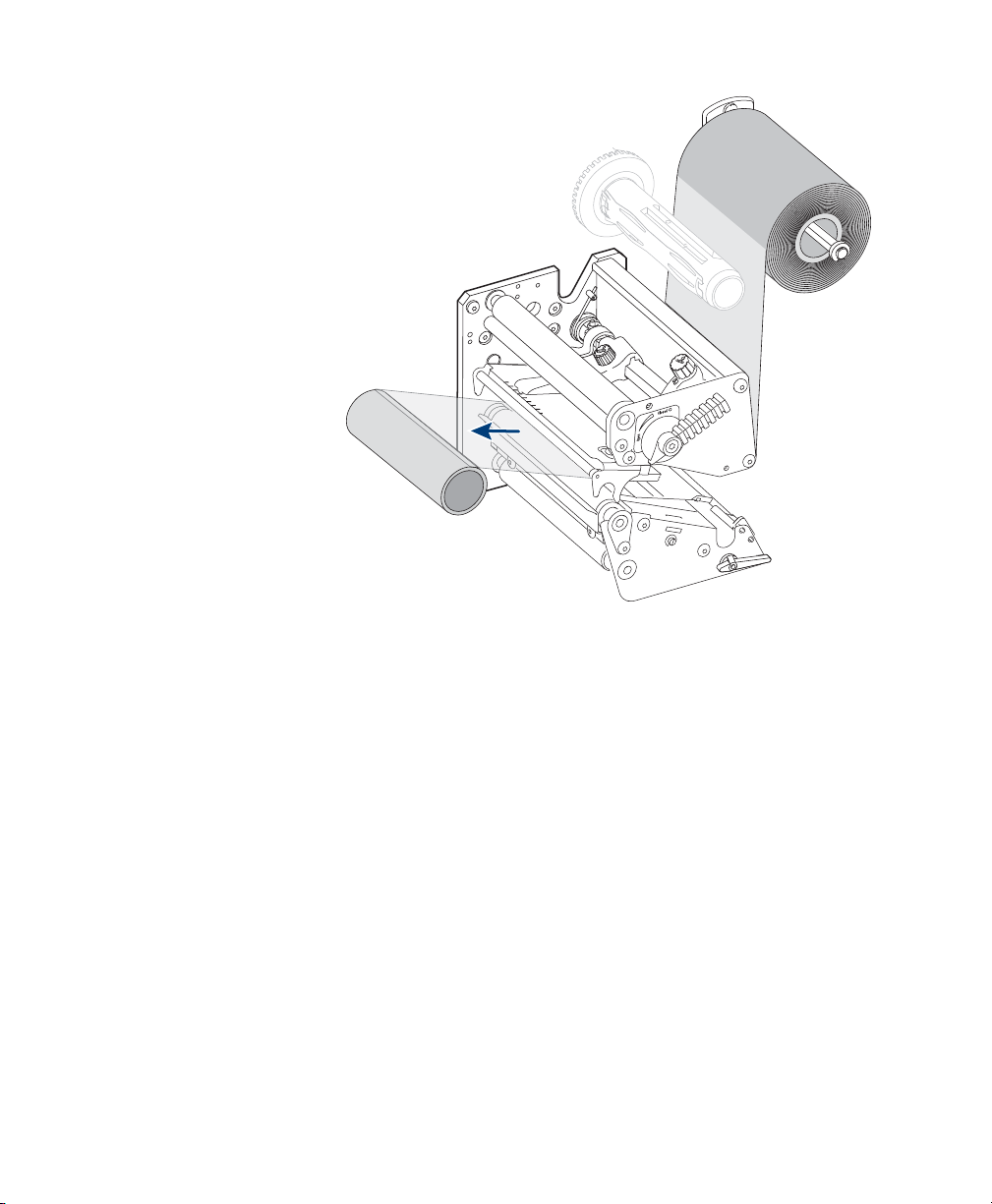
Loading Ribbon
Chapter 1 — Learning About the PA30
4 Press the down arrow key. Media: Media Size appears in the
display.
5 Press the right arrow key several times until you see this text in
the display:
6 Press the down arrow and then press Enter. The PA30 feeds
out labels until the firmware has determined the best position
for the media.
7 Press Setup to exit Setup mode.
The PA30 can print on labels, tickets, tags, and continuous stock
using thermal transfer printing with a special ink-coated ribbon.
The PA30 can use transfer ribbon rolls wound with the inkcoated side facing either outward or inward. Illustrations in this
section show the ink-coated side facing inward, and media is
omitted from the illustrations for clarity.
Note: By default, the PA30 is configured to use an 83-mm
diameter ribbon. To use larger diameter ribbon (such as 90-mm),
you need to send the SYSVAR(53)=90 Fingerprint command to
the PA30.
For more information on using Fingerprint with the PA30, see
“Programming Applications for the PA30” on page 40.
For more information on all Fingerprint commands, see the
Intermec Fingerprint v8.xx Programmer’s Reference Manual.
To load thermal transfer ribbon
1 Open the PA30 access door.
PA30 Print Engine User’s Manual 19
Page 34

Chapter 1 — Learning About the PA30
2 Turn the printhead lift lever counterclockwise to open the
printhead.
3 If you are reloading ribbon, remove the empty ribbon core or
unused ribbon.
4 Squeeze the ends of the ribbon supply bobbin and slide the
bobbin along the shaft. The bobbin snaps into several grooves
along the shaft that correspond to these ribbon widths:
20 PA30 Print Engine User’s Manual
Page 35

55-60 mm
(2.1-2.3 in)
88-90 mm
(3.5 in)
110 mm
(4.3 in)
Chapter 1 — Learning About the PA30
• 55 to 60 mm (2.16 to 2.3 in)
• 88 to 90 mm (3.5 in)
• 110 mm (4.3 in)
Snap the bobbin into the correct groove for the size of ribbon
you want to use. The bobbin should be centered in the ribbon
roll for best results. The wider the ribbon, the closer the
bobbin should be to the front of the PA30.
Bobbin Placement: The bobbin should be in the center of the roll of ribbon.
PA30 Print Engine User’s Manual 21
Page 36

Chapter 1 — Learning About the PA30
5 Press the ribbon roll onto the ribbon supply bobbin.
6 Route the ribbon through the print mechanism. Pull out
about 20 cm (8 in) of ribbon.
22 PA30 Print Engine User’s Manual
Page 37
Chapter 1 — Learning About the PA30
7 Keep the ribbon pulled taut through the print mechanism
and turn the printhead lever counterclockwise to the Closed
position to lock the ribbon in place.
8 Press the cardboard core at the front end of the ribbon onto
the rewind hub. During printing, the rewind hub rotates
counterclockwise.
9 Turn the printhead lever to the Open position.
PA30 Print Engine User’s Manual 23
Page 38
Chapter 1 — Learning About the PA30
10 Turn the rewind hub to wind up the ribbon until all the
transparent leader is taken up. Keep the ribbon tight.
11 Turn the printhead lever to the Closed position.
12 Close the PA30 access door.
Adjusting the Print Mechanism
After you install media and ribbon, you may need to adjust the
PA30 print mechanism to get the best print quality.
• If you are using media less than the full size width, Intermec
recommends you adjust the printhead pressure arm. For help,
see the next section.
• If you are using thicker or thinner media than standard, you
can adjust the printhead pressure to darken or lighten the
print quality as needed. For help, see “Adju sti ng th e
Printhead Pressure” on page 26.
24 PA30 Print Engine User’s Manual
Page 39

• If you are using media with slots, gaps, or black marks that
indicate label edges, you can adjust the label stop sensor (LSS)
to position the sensor for best results. For help, see “Ad ju st in g
the Label Stop Sensor” on page 28.
Adjusting the Pressure Arm
The PA30 is factory-adjusted for full size media width. If you use
media of less than 120 cm (4.72 in) width, you should adjust the
printhead pressure arm to center the arm over the media and
maintain even pressure.
To adjust the pressure arm
1 Open the PA30 access door.
2 Turn the printhead lift lever counterclockwise to raise the
printhead.
3 Remove ribbon if any ribbon is installed.
4 Turn the pressure arm lock knob counterclockwise to loosen
the knob.
5 Slide the pressure arm in or out until the arrow on the tip of
the arm is centered over the media. To slide the arm, push it
along the bar below the pressure arm lock knob. If the arm is
difficult to move, push down on the printhead to disengage
the pressure arm magnet.
Chapter 1 — Learning About the PA30
PA30 Print Engine User’s Manual 25
Page 40

Chapter 1 — Learning About the PA30
Center of
media
Pressure Arm Adjustment: Loosen the pressure arm lock knob and slide
the pressure arm until it is centered over the media.
Pressure arm
lock
6 Turn the pressure arm lock knob clockwise to lock the
pressure arm in place.
7 Adjust the media edge guides.
8 Reload ribbon if necessary.
9 Close the PA30 access door.
Adjusting the Printhead Pressure
The pressure of the thermal printhead against the ribbon or
direct thermal media is factory adjusted. However, using thicker
or thinner media than normal could require adjusting the
printhead pressure for best print quality.
To adjust printhead pressure
1 Open the PA30 access door.
2 Turn the pressure adjustment knob clockwise to increase the
pressure and darken the print, or counterclockwise to decrease
26 PA30 Print Engine User’s Manual
Page 41

Chapter 1 — Learning About the PA30
Printhead
pressure
adjustment
the pressure and lighten the print. You should print a few test
labels to check the quality after adjusting the pressure.
Or, you can locate the basic setting as follows:
a Turn the pressure adjustment knob counterclockwise until
there is no resistance. To test this, place a piece of media
under the printhead and pull it out. There should be little
or no resistance as you pull the media out.
b Turn the knob five full turns clockwise.
After you locate the basic setting, repeat the first part of Step 2
to determine the correct adjustment for your media.
PA30 Print Engine User’s Manual 27
Page 42
Chapter 1 — Learning About the PA30
Upper sensor
Gaps in
media
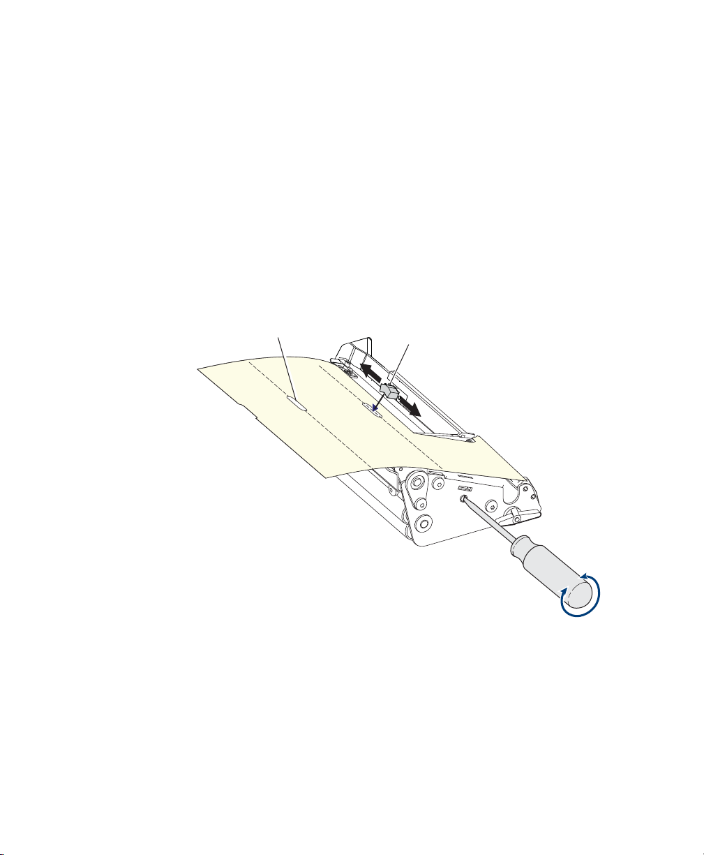
Adjusting the Label Stop Sensor
The label stop sensor (LSS) controls the media feed by detecting
gaps between labels, or slots or black marks in continuous stock.
For best results, the LSS should be aligned with the gaps, slots, or
black marks, or with the front tips of irregularly shaped labels.
To adjust the label stop sensor
• Turn the LSS adjusting screw clockwise to move the LSS
towards the back wall of the media compartment, or
counterclockwise to move away from the back wall. Move the
LSS until the center point of the upper sensor is aligned with
the center of the gaps or slots to be detected.
Positioning the Label Stop Sensor: Align the center point of the upper
sensor with the gaps to be detected. The printhead is omitted here for
clarity.
You can also position the LSS by using the linear markings on
the lower guide plate as a reference. The markings are 1 cm
(.4 in) apart. This method is especially useful for black marks.
Measure the lateral position of the marks before loading the
media, and adjust the LSS accordingly.
28 PA30 Print Engine User’s Manual
Page 43

Chapter 1 — Learning About the PA30
Testing the Label Stop Sensor
1 Make sure the PA30 is set up correctly for the loaded media
type.
2 Press Shift and Feed at the same time to perform a testfeed.
The media advances through the print mechanism.
3 Make sure there is a label (not a gap or mark) at the LSS.
4 Check that the media is routed as close to the back of the
media compartment as the guides allow.
5 Press Setup. The PA30 enters Setup mode.
6 Use the arrow keys to navigate to PRINT DEFS: LSS TEST:
LSS AUTO. The cursor appears in the lower center of the
display.
7 To test gap or slot detection, raise the printhead and slowly
pull out the media. When the LSS detects a gap or slot, the
cursor moves to the right.
To test black mark detection, raise the printhead and slowly
pull out the media. When the LSS detects a black mark, the
cursor moves to the left.
If necessary, press the down arrow key to refresh the cursor
center position.
8 If the LSS behaves as described in Step 7, the LSS is working
properly.
If the LSS does not behave as described in Step 7, check these
items:
• Is the LSS laterally aligned with the slots or black marks?
• Are the upper and lower parts of the LSS aligned with each
other?
• Is the transfer ribbon loaded properly so that it does not
interfere with the LSS?
• Are the label stop sensors free from dust?
• Are the guides free from stuck labels or other objects that
may interfere with the light between the upper and lower
sensors?
PA30 Print Engine User’s Manual 29
Page 44

Chapter 1 — Learning About the PA30
• Does the media have preprint areas that may be interfering
with LSS detection?
• Is there enough contrast between the black marks and the
surrounding areas?
• Does the liner have too little transparency?
• Does the LSS work with other types of media?
Configuring the PA30
You can configure settings on the PA30:
• via the web browser interface. For more information, see the
next section.
• by placing the PA30 in Setup mode and using the printer
keypad and display. However, not all settings can be changed
in Setup mode. For more information, see Chapter 5, “Using
Setup Mode.”
• by sending Fingerprint or Direct Protocol commands to the
PA30 via a serial connection from your desktop PC. For more
information, see the Intermec Fingerprint v8.xx Programmer’s
Reference Manual.
Using the Web Browser Interface
After the PA30 has been assigned an IP address, you can manage
and configure it from any desktop PC on the network using a
web browser.
To connect to the PA30 using a web browser
1 On the desktop PC, open a web browser.
2 In the browser Address field, type the PA30 IP address and
press Enter. The PA30 main web page appears.
30 PA30 Print Engine User’s Manual
Page 45
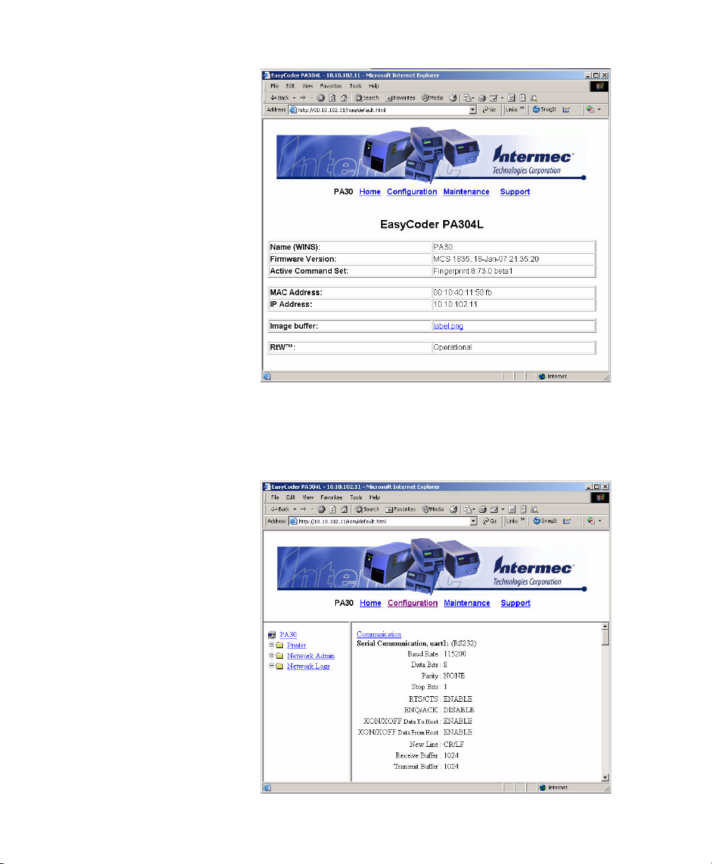
Chapter 1 — Learning About the PA30
3 Click Configuration. A dialog box appears, prompting you
for a username and password.
4 Ty pe
admin in the username field and pass in the password
field, and then click OK. This screen appears:
PA30 Print Engine User’s Manual 31
Page 46

Chapter 1 — Learning About the PA30
From this screen you can configure all PA30 settings.
• To configure applicator port settings, see Chapter 2,
“Using the PA30 in an Applicator.”
• To configure serial and network communication settings,
see Chapter 3, “Configuring Communication Settings.”
• To configure print engine and media settings, Chapter 4,
“Configuring Print Engine and Media Settings.”
32 PA30 Print Engine User’s Manual
Page 47

2
Using the PA30 in an Applicator
This chapter explains how to use the PA30 in an applicator and
includes these sections:
• Applicator Port Styles: Describes the Z-Style, S-Style, and IStyle applicator port interfaces.
• Configuring Applicator Port Settings: Explains how to
configure and change settings for each applicator port style.
• Programming Applications for the PA30: Describes
Intermec’s Fingerprint printer language and how to use it
when developing applications for the PA30.
• Using External Applicator Signals: Describes how the PA30
handles input and output signals from the applicator.
PA30 Print Engine User’s Manual 33
Page 48

Chapter 2 — Using the PA30 in an Applicator
Applicator Port Styles
The PA30 can be configured for a Zebra-style (“Z-Style”)
applicator interface or a Sato-style (“S-Style”) applicator
interface. Each interface requires different setup parameters,
which can be configured via the PA30 web browser interface or in
Setup Mode.
The PA30 also supports an Intermec-style (“I-Style”) interface,
which adds additional functionality to the basic Zebra or Sato
interface.
For more information on applicator port settings, see the next
section.
For pinout diagrams and signal information, see “Port Pinouts”
on page 117.
Configuring Applicator Port Settings
The PA30 supports three different applicator modes:
• Z-Style. Choose this mode for a Zebra-type applicator.
• S-Style. Choose this mode for a Sato-type applicator.
• I-Style. This mode combines Z-Style or S-Style settings with
the ability to trigger external I/O systems via the External
Error port.
You can configure applicator port settings:
• via the web browser interface. For help, see the next section.
• in Setup Mode. For more information, see Chapter 5Z-Style,
“Using Setup Mode.”
• by sending commands from another application.
Using the Web Browser Interface
To configure applicator port settings
1 Open a web browser interface to the PA30. For more
information, see “Using the Web Browser Interface” on
page 30.
2 From the menu, click Printer > Applicator Port. The
Configuration [Applicator] screen appears.
34 PA30 Print Engine User’s Manual
Page 49
Chapter 2 — Using the PA30 in an Applicator
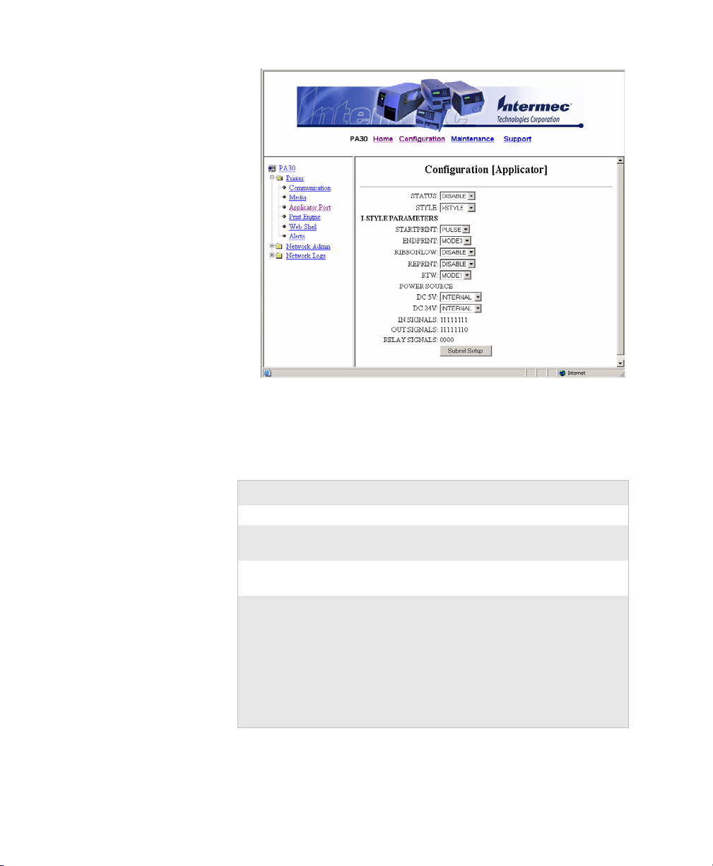
3 Choose settings from the drop-down lists. For more
information, see the next table.
4 Click Submit Setup. The settings are saved.
Applicator Port Settings Descriptions
Setting Description
Status Enables or disables Applicator mode.
Style Select from I-Style, Z-Style, or S-Style. For more
information, see “Applicator Port Styles” on page 34.
Startprint Choose either Level or Pulse. For more information, see
“Startprint” on page 37.
Endprint Choose from:
•OFF
•Mode 1/Type 3
•Mode 2/Type 4
•Mode 3/Type 1
•Mode 4/Type 2
For more information, see “Endprint” on page 38.
PA30 Print Engine User’s Manual 35
Page 50

Chapter 2 — Using the PA30 in an Applicator
Applicator Port Settings Descriptions (continued)
Setting Description
Ribbonlow Enables or disables the PA30 low ribbon alert message.
For more information, see “Ribbon Low” on page 39.
Reprint Enables or disables reprinting the last label sent to the
printer (by using the Reprint in signal). For more
information, see “Reprint” on page 38.
RTW Configures the Ready-to-Work indicator on the PA30
front panel. Asserting this signal turns the Ready-toWork indicator on (steady blue). Choose from:
• Mode 1 - Signal is asserted low when no events are
active in the System Health Monitor (SHM).
• Mode 2 - Signal is asserted low when the printer
motor is idle.
• Mode 3 - Signal is asserted low when the printer
motor is idle and no events are active in the SHM.
For more information, see “RTWOUTEXT” on
page 39.
DC 5V Configures the PA30 to use either its internal power
supply or an external supply (connected to the External
Power port) to provide +5VDC to the
Z-Style and S-Style ports.
DC 24V Configures the PA30 to use either its internal power
supply or an external supply (connected to the External
Power port) to provide +24VDC to the Z-Style and SStyle ports.
In Signals (Read-only) Shows the current state of the 8 in signals,
from left (lowest numbered port) to right. 0 indicates
low, 1 indicates high.
For more information, see “About PA30 In Signals” on
page 37.
36 PA30 Print Engine User’s Manual
Page 51

Chapter 2 — Using the PA30 in an Applicator
Applicator Port Settings Descriptions (continued)
Setting Description
Out Signals Shows the current state of the 8 out signals, from left
(lowest numbered port) to right. 0 indicates low, 1
indicates high.
Note: Out signals can only be configured in Setup
Mode.
For more information, see “About PA30 Out Signals”
on page 38.
Relay Signals
(Read-only)
Error on
Pause
Error Port Enables or disables the PA30 External Error port.
Shows the current state of the four relay signals, from
left (lowest numbered port) to right. 0 indicates low, 1
indicates high.
On the applicator interface, the relay signals determine
whether an internal or external power source is used.
When the applicator port is disabled, use the
Fingerprint PORTOUT(PORT) command to
configure the power source.
Enable this setting to set the “service required” signal
when the PA30 is paused.
This setting is supported by Z-Style only.
About PA30 In Signals
This section describes the PA30 in signals.
Note: All in signals are asserted low and de-asserted high.
Startprint
Starts a print job. Choose either:
• Level: The PA30 starts printing labels when the startprint
signal is asserted, and continues printing until the signal is deasserted.
• Pulse: The PA30 prints one label when the startprint signal is
asserted. The startprint signal must be de-asserted and then
asserted to print the next label.
Feed
Feeds a single label. Not supported by S-Style.
PA30 Print Engine User’s Manual 37
Page 52

Chapter 2 — Using the PA30 in an Applicator
Pause
Tog g le s be tw e en Pa us e m o de an d printing. Not supported by SStyle.
Reprint
Reprints the last valid label.
Apperr1
Applicator error 1.
Apperr2
Applicator error 2.
Apperr3
Applicator error 3.
RTWINEXT
External input signal for the Ready-to-Work indicator, which you
can use to monitor the operational status of the entire system.
About PA30 Out Signals
This section describes the PA30 out signals.
Note: Unless described otherwise, all out signals are asserted low
and de-asserted high.
Data Ready
Asserted when the PA30 is ready to receive a startprint signal and
execute the current print job. De-asserted when the print cycle
ends. Not supported by S-Style.
Endprint
Asserted during or after a print cycle. The endprint signal also
behaves differently depending on the applicator port endprint
mode. When the startprint signal is received, the endprint signal
may or may not be asserted.
There are five options to choose from:
• Off: Endprint signal is never asserted.
• Mode 1 (Z-Style)/Type 3 (S-Style): Asserted low during
print/feed cycle.
• Mode 2 (Z-Style)/Type 4 (S-Style): Asserted high during
print/feed cycle.
38 PA30 Print Engine User’s Manual
Page 53

Chapter 2 — Using the PA30 in an Applicator
• Mode 3 (Z-Style)/Type 1 (S-Style): Asserted low for at least
20 ms after print/feed cycle end.
• Mode 4 (Z-Style)/Type 2 (S-Style): Asserted high for at least
20 ms after print/feed cycle end.
Media Out
Asserted when the PA30 is out of media. Activates an
shmPaperOut event in the System Health Monitor (SHM). Deasserted when the same event is deactivated.
Ribbon Low
Asserted when the ribbon roll diameter drops below a predefined
level. De-asserted while the roll diameter remains above the
predefined level.
Ribbon Out
Asserted when the PA30 is out of ribbon. Activates an
shmRibbonOut event in the System Health Monitor (SHM).
De-asserted when the same event is deactivated.
RTWOUTEXT
External output signal for the Ready-to-Work indicator.
Behavior depends on the current setup. Signal may be asserted
when there are no active events in the System Health Monitor
(SHM), when the PA30 motor is idle, or both. This has the effect
of turning on the Ready-to-Work indicator on the PA30 front
panel.
This signal is inactive when the Error Port option is disabled.
SERVICEREQ (Service Required)
Asserted low when an event in the System Health Monitor
(SHM) is activated. De-asserted when no events are active in the
SHM. Supported only by I-Style.
A “service required” event is also activated when the Error Port is
enabled and any of the four applicator error in signals is detected.
This signal is also asserted when the Error on Pause option is
enabled.
PA30 Print Engine User’s Manual 39
Page 54

Chapter 2 — Using the PA30 in an Applicator
Programming Applications for the PA30
The PA30 includes Intermec Fingerprint v8.7x, a programming
language that resides on the printer. Fingerprint is an easy-to-use
programming tool for label formatting and printer
customization.
Fingerprint also includes a slave protocol, Intermec Direct
Protocol, which allows layouts and variable data to be
downloaded from a host and combined into labels, tickets, and
tags with a minimum of programming. Intermec Direct Protocol
also includes a versatile error handler and a flexible counter
function.
For more information on using Fingerprint, see these documents:
• Intermec Fingerprint v8.xx Programmer’s Reference Manual
(P/N 937-005-xxx). This manual includes detailed
information on all Fingerprint programming instructions as
well as program-related information.
• Intermec Fingerprint 8.xx Tutorial (P/N 1-960608-xx). This
tutorial walks you through the basics of using Fingerprint to
create printer applications.
• Intermec Direct Protocol v8.xx Programmer’s Reference Manual
(P/N 1-960597-xx). Includes in-depth information on Direct
Protocol instructions and use.
These documents are available for free from the Intermec web
site. For information on downloading these manuals, see “To
download documents” on page xiv.
Fingerprint Commands for the PA30
The ON PORTIN, PORTIN, PORTOUT, and ON
PORTOUT Fingerprint commands support applicator
functionality for the PA30. These commands are functional
when the PA30 applicator port status is enabled.
This section includes basic information for each of these
commands. For more information on Fingerprint, see the
Fingerprint programmer’s reference manual.
40 PA30 Print Engine User’s Manual
Page 55

Chapter 2 — Using the PA30 in an Applicator
ON PORTIN
This command allows a Fingerprint application to detect in
signals. If a particular in signal is asserted, the application moves
to the subroutine responsible for carrying out tasks related to that
in signal. One command is available for detection of each of the 8
in signals.
This command is not supported by the Intermec Direct Protocol.
Example
ON PORTIN.STARTPRINT GOSUB nnn
PORTIN
This command is a version of the PORTIN(PORT) command
and checks the current state of a specified signal. This command
returns -1 if the signal is asserted, or 0 if the signal is de-asserted.
This command is supported by Fingerprint and Direct Protocol.
Examples
PORTIN.STARTPRINT
or
PORTIN.RIBBONLOW
PORTOUT
Supports manually modifying the dataready signal. PORTOUT
is not allowed when the applicator port style is set to S-Style.
This command is not supported by Direct Protocol.
Example
PORTOUT.DATAREADY ON
PORTOUT DATAREADY OFF
where on asserts the dataready signal low and off de-asserts the
dataready signal high.
ON PORTOUT
This command allows a Fingerprint application to detect when
out signals have been reset to default values. The command
moves to a specified subroutine whenever the applicator port
status is enabled, and whenever the applicator port style is
changed.
Example
ON PORTOUT.RESET GOSUB nnn
PA30 Print Engine User’s Manual 41
Page 56

Chapter 2 — Using the PA30 in an Applicator
Using External Applicator Signals
The PA30 responds to external applicator port signals differently,
depending on whether your application is using Fingerprint or
Intermec Direct Protocol.
Fingerprint and Applicator Signals
When you use Fingerprint, all in signals and the Dataready out
signal are handled by Fingerprint. Other out signals are handled
by firmware.
Feed
When the Feed in signal is received, the application moves to a
specified subroutine that feeds labels until the Feed in signal is
de-asserted.
Example
10 ON PORTIN.FEED GOSUB 200
...
200 FORMFEED
210 RETURN
Pause
When the Pause in signal is received, the application moves to a
specified subroutine that finishes the current print job and then
places the PA30 in pause mode.
Example
10 ON PORTIN.PAUSE GOSUB 90
...
90 pause printer
Startprint
When the Startprint signal is received, the application moves to a
specified subroutine that starts the print job. The Startprint
signal must be preceded by the dataready signal as seen in this
example.
Example
10 PORTOUT.DATAREADY on
20 ON PORTIN.STARTPRINT GOSUB 60
...
60 my print routine
70 PRINTFEED
80 RETURN
42 PA30 Print Engine User’s Manual
Page 57

Chapter 2 — Using the PA30 in an Applicator
Reprint
When the Reprint signal is received, the application moves to a
specified subroutine that reprints the last valid label.
Example
...
100 ON PORTIN.REPRINT GOSUB 150
...
150 PRINTFEED -1,1
160 RETURN
Printfeed
The dataready signal must be set manually by the Fingerprint
application.
Handling External Applicator Errors
When an error signal (apperr1, apperr2, or apperr3) is
received, the application moves to a specified subroutine that
takes action based on error severity.
Example
...
60 ON PORTIN.APPERR1 GOSUB 100
...
100 perform error handling
110 RETURN
Handling Internal System Errors
For internal system errors, the system error signal status can be
read at any time within the application so appropriate measures
can be taken. When any of these errors occur, the appropriate out
signal (including the error) is asserted:
• Ribbon low
• Ribbon out
•Media low
•Media out
•RFID tag error
Example
10 IF PORTIN.RIBBONLOW GOTO 200
...
200 perform error handling
210 RETURN
PA30 Print Engine User’s Manual 43
Page 58

Chapter 2 — Using the PA30 in an Applicator
Resetting Out Signals
Out signals are reset to their default values when certain options
are changed by using the SETUP menu. When the reset is
detected, the application moves to a specified subroutine and
performs the tasks necessary to reinitialize the print engine.
Example
10 ON PORTOUT.RESET GOSUB 150
...
150 perform initialization
160 RETURN
Direct Protocol and Applicator Signals
In Direct Protocol, all in and out signals are handled by the
Direct Protocol firmware.
Feed
There are two ways to trigger blank label feeding:
• by manually pressing Feed on the PA30 front panel. The
PA30 feeds a single blank label.
• by using the Feed in signal. When this signal is detected, the
PA30 feeds blank labels for as long as the internal applicator
flag indicates that the Feed signal is asserted.
Pause
The applicator can toggle the current pause state by using the
pause in signal to simulate pressing Pause on the PA30 front
panel. When the PA30 is in pause state, you can press Setup on
the PA30 front panel and place the print engine in Setup Mode
for manual configuration.
Startprint
When the printfeed command is executed, the print process sets
the dataready signal and then waits for the startprint signal to be
detected before proceeding with the print job.
The print process will not set another dataready signal until the
current print job de-asserts the previous dataready signal. This
prevents the PA30 from printing a new label before the previous
label is completed.
Reprint
This signal works much the same way as startprint. The reprint
signal is detected under two conditions:
44 PA30 Print Engine User’s Manual
Page 59

Chapter 2 — Using the PA30 in an Applicator
•when the PA30 is idle.
• when the PA30 is waiting for a startprint signal during the
execution of a printfeed command.
The PA30 prints only one label at a time.
Handling External Applicator Errors
The external applicator error in signals (APPERR1, APPERR2,
APPERR3, RTWINEXT) should be asserted when external applicator
errors occur. When one of these signals is detected, an associated
event is activated in the System Health Monitor (SHM). When
the issue causing the error has been resolved and the error signals
are de-asserted, the events are deactivated in the SHM.
Handling Internal System Errors
When a system error occurs that activates an event in the SHM,
the “service required” signal is asserted. The external RTW out
signal can be de-asserted, depending on the current print engine
RTW setting.
When any of these errors occur, the appropriate out signal
(including the error) is asserted:
• Ribbon low
• Ribbon out
•Media low
•Media out
•RFID tag error
For more information on error messages, see “Error Message and
Ready-to-Work Indicator Descriptions” on page 110.
Error Messages
ERRNOAPP
Message: Operation not allowed. Applicator Port disabled.
Cause: Application sent an applicator port command to the PA30 and
the applicator port is disabled.
Error Number: 88
ERRAPP
Message: Operation not allowed. Applicator Port enabled.
PA30 Print Engine User’s Manual 45
Page 60

Chapter 2 — Using the PA30 in an Applicator
Cause: Application sent the Fingerprint command PORTOUT(PORT)
ON|OFF
port is enabled.
Error Number: 89
on a port used by the applicator port when the applicator
ERRINPUTON
Message: Operation not allowed in Direct Protocol.
Cause: Running the PORTOUT.DATAREADY ON|OFF or
PORTIN.<SIGNAL> GOSUB XXX commands when the PA30 is
using Direct Protocol.
Error Number: 90
EAPPERR1
Message: Applicator Error 1.
Cause: AppErr1 in signal detected.
Result: Activates event in System Health Monitor (SHM).
Error Number: 1340
EAPPERR2
Message: Applicator Error 2.
Cause: AppErr2 in signal detected.
Result: Activates event in System Health Monitor (SHM).
Error Number: 1341
EAPPERR3
Message: Applicator Error 3.
Cause: AppErr3 in signal detected.
Result: Activates event in System Health Monitor (SHM).
Error Number: 1342
ERTWINEXT
Message: RTW Extenal Error.
Cause: RTWExternal in signal detected.
Result: Activates event in System Health Monitor (SHM).
Error Number: 1343
ENODATAREADY
Message: Dataready not enabled.
46 PA30 Print Engine User’s Manual
Page 61

Cause: Application sent a PRINTFEED in Fingerprint when the applicator
Result: Terminates the printfeed command without printing a label.
Error Number: 1344
Display Messages
Chapter 2 — Using the PA30 in an Applicator
port is enabled, the style is set to I-Style or Z-Style, and the
dataready signal is not enabled.
These messages appear in the PA30 display under certain
conditions when a
PRINTFEED command is run.
Message:
APPLICATOR PORT: Wait for signal.
Cause: Running a PRINTFEED command blocks execution until a
startprint signal is received. The message appears when execution
has been blocked for a few seconds.
Message:
APPLICATOR PORT: Wait for reprint.
Cause: Running a PRINTFEED -1,1 command blocks execution until a
reprint signal is received. The message appears when execution
has been blocked for a few seconds.
PA30 Print Engine User’s Manual 47
Page 62

Chapter 2 — Using the PA30 in an Applicator
48 PA30 Print Engine User’s Manual
Page 63

3
Configuring Communication Settings
This chapter explains how to configure communication settings
on the PA30, and assumes you are using the web browser
interface to configure settings on the PA30. This chapter
includes:
• Changing Serial Communication Settings
•Changing the Standard I/O Port
• Changing TCP/IP Settings
• Changing Network Administrator Settings
• Changing DDNS Settings
• Configuring Network Logging
• Configuring Wireless Network Settings
• Changing Wireless LAN Settings
• Configuring 802.1x Security Settings
PA30 Print Engine User’s Manual 49
Page 64

Chapter 3 — Configuring Communication Settings
Configuring Communication Settings for the PA30
This chapter assumes you are using the web browser interface to
configure settings. For more information, see “Using the Web
Browser Interface” on page 30.
To communicate with the PA30, you can:
• connect the PA30 directly to a host PC via a serial
connection. To configure serial connection settings, see the
next section.
• connect the PA30 to your Ethernet network. For help, see
“Changing TCP/IP Settings” on page 52.
If you ordered the 802.11 wireless option, you can communicate
with the PA30 over your wireless network. For more information,
see “Configuring Wireless Network Settings” on page 58.
To change communication settings in Setup mode, see Chapter
5, “Using Setup Mode.”
Changing Serial Communication Settings
1 Open a web browser interface to the PA30. For help, see
“Using the Web Browser Interface” on page 30.
2 From the menu, click Printer > Communication. The
Configuration [Communication] screen appears.
50 PA30 Print Engine User’s Manual
Page 65

Chapter 3 — Configuring Communication Settings
3 Choose settings from the drop-down lists, or specify values in
the entry fields. For more information, see the next table.
4 Click Submit Setup. The settings are saved.
Serial Communication Settings
Setting Description
Baud Rate Baud rate for serial communications with a host
PC. Default is 9600.
Data Bits Number of bits defining a character. Default is 8.
Parity Default is None.
Stop Bits Number of bits defining the end of a character.
Default is 1.
RTS/CTS Enable or disable.
ENQ/ACK Enable or disable.
XON/XOFF
Data to Host
XON/XOFF
Data from Host
New Line New line character. Default is CR/LF.
Receive Buffer Receive buffer size in bytes. Default is 1024.
Transmit Buffer Transmit buffer size in bytes. Default is 1024.
Enable or disable.
Enable or disable.
Note: The PA30 can print a list of the current serial
communication settings. For more information, see “Printing
Test Labels and Setup Information” on page 96.
Changing the Standard I/O Port
By default, the PA30 communicates with a host PC via the serial
port, also known as “uart1:”. You can change the default I/O port
by using the web browser interface.
Note: You can also change the standard I/O port from the
Intermec Shell program. For more information, see “Abo ut
Intermec Shell” on page 88.
To change the default I/O port
1 From the menu, click Printer > Web She ll. The
Configuration [Web Shell] screen appears.
PA30 Print Engine User’s Manual 51
Page 66

Chapter 3 — Configuring Communication Settings
2 Choose an option from the Standard I/O drop-down list:
• auto - The PA30 checks possible I/O ports and uses the
port with the best connection.
• uart1: - serial port
• net1: - network interface (Ethernet or wireless)
• usb1: - USB port
3 Click Submit setup. The changes are saved.
Changing TCP/IP Settings
1 From the menu, click Network Admin > TCP/IP. The
Configuration [TCP/IP] screen appears.
52 PA30 Print Engine User’s Manual
Page 67

Chapter 3 — Configuring Communication Settings
2 Choose options from the drop-down lists and enter values in
the entry fields. For more information, see the next table.
3 Click Submit TCP/IP settings. The changes are saved.
TCP/IP Settings Descriptions
Setting Description
IP Selection Determines how the PA30 is assigned TCP/IP
parameters:
• DHCP: A DHCP server assigns TCP/IP
parameters.
• BOOTP: A BOOTP server assigns TCP/IP
parameters.
• DHCP+BOOTP: TCP/IP parameters are
assigned by either a DHCP or BOOTP
server.
• Manual: TCP/IP parameters, including IP
address, netmask, default router, and WINS
addresses, are set manually.
IP Address Specifies the IP address if TCP/IP parameters
are manually assigned, or shows the IP address
assigned by a DHCP or BOOTP server.
PA30 Print Engine User’s Manual 53
Page 68

Chapter 3 — Configuring Communication Settings
TCP/IP Settings Descriptions (continued)
Setting Description
Netmask Specifies the netmask address if TCP/IP
parameters are manually assigned, or shows the
netmask address assigned by a DHCP or
BOOTP server.
Default Router Specifies the default router address of TCP/IP
parameters are manually assigned, or shows the
default router address assigned by a DHCP or
BOOTP server.
Nameserver Specifies the name server for the network.
Primary WINS
Server
Secondary WINS
Server
net1 TCP Port
Number
net1 Queueing Enables or disables queueing for TCP
Specifies the primary WINS server addresses if
TCP/IP parameters are manually assigned, or
shows the addresses assigned by a DHCP or
BOOTP server. Not configurable in Setup
mode.
Specifies the secondary WINS server addresses
if TCP/IP parameters are manually assigned, or
shows the addresses assigned by a DHCP or
BOOTP server. Not configurable in Setup
mode.
Specifies the port number for TCP connections
via Ethernet. Not configurable in Setup mode.
connections via Ethernet.
Note: The PA30 can print a list of the current TCP/IP settings.
For more information, see “Printing Test Labels and Setup
Information” on page 96.
54 PA30 Print Engine User’s Manual
Page 69

Chapter 3 — Configuring Communication Settings
Changing Network Administrator Settings
1 From the menu, click Network Admin > General. The
Configuration [General] screen appears:
2 Enter values in the entry fields, or choose values from the
drop-down lists. For more information, see the next table.
To change the administrator password:
a Type the old password in the Old admin Password entry
field.
b Type the new password in the New admin Password entry
field.
c Type the new password again in the Retype Password
entry field.
To restrict access to PA30 settings:
a In the Restrictions entry fields, type
admin if you want
only the PA30 administrator to change settings, or
admin,user if you want anyone to be able to change
PA30 settings.
The user access settings include:
• Users allowed to UPDATE - change and save any
settings
PA30 Print Engine User’s Manual 55
Page 70

Chapter 3 — Configuring Communication Settings
• Users allowed to read/set protected lan1 settings change and save passwords and permissions
• Users allowed to change NETWORK settings - change
and save network settings only
• Users allowed to do SETUP KEY ON - change and
save Setup key enabling
3 Click Submit General settings. The changes are saved.
Network Administrator Settings Descriptions
Setting Description
Printer Name Name for the PA30.
System Location Location of the PA30.
System Contact Contact person, such as the network administrator,
for the PA30.
HP JetAdmin
Support
Control Panel
Access
Enables (ON) or disables (OFF, default) HP
JetAdmin print server support.
Enables or disables the Setup key on the PA30.
Disable Control Panel Access to prevent users from
pressing Setup and changing settings manually.
Configuring DDNS Settings
1 From the menu, click Network Admin > DDNS. The
Configuration DDNS screen appears.
56 PA30 Print Engine User’s Manual
Page 71

Chapter 3 — Configuring Communication Settings
2 Choose an option from the list:
• Click Enable to enable DDNS.
• Click Enable with TSIG to enable DDNS using a
transaction signature (TSIG) for better security.
• Click Disable to disable DDNS.
3 Enter information in the entry fields. For more information,
see the next table.
4 Click Submit changes. The changes are saved.
DDNS Settings Descriptions
Setting Description
Alias DDNS alias for the PA30.
Zone DDNS zone the PA30 should subscribe to.
TSIG key Key used for TSIG authentication.
TSIG key name Name of the TSIG key. Must match the TSIG key
name on the server.
Timeserver Time server used for authentication.
Configuring Network Logging
You can use the web browser interface to enable or disable data
logging, which shows the status of XML print jobs sent to the
PA30.
To enable network logging
1 From the menu, click Network Logs > XML Printing Log.
The XML Printing Log appears.
PA30 Print Engine User’s Manual 57
Page 72

Chapter 3 — Configuring Communication Settings
2 Click Enable Data Log to enable XML print job logging.
Configuring Wireless Network Settings
If the PA30 includes the EasyLAN Wireless option, you can
communicate with the PA30 over your wireless network.
• For information on configuring general wireless network
settings including network name (SSID), WEP keys, WPA
pre-shared keys, and roaming settings, see the next section.
• For information on configuring 802.1x security settings, see
“Changing 802.1x Security Settings” on page 60.
Changing Wireless LAN Settings
1 From the menu, click Network Admin > Wireless LAN.
This screen appears:
58 PA30 Print Engine User’s Manual
Page 73
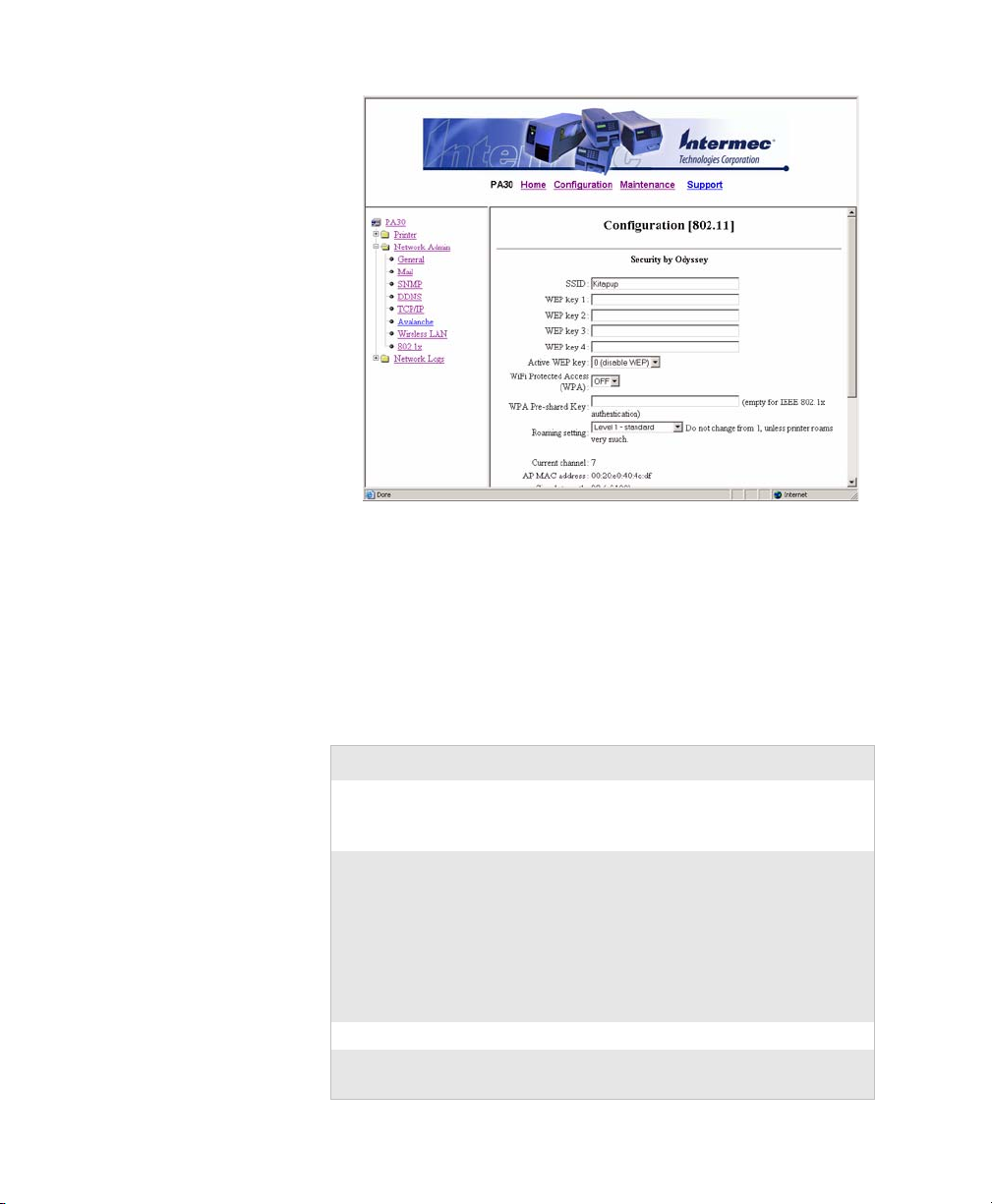
Chapter 3 — Configuring Communication Settings
The lower part of this screen includes the current wireless
channel, the signal strength and MAC address of the currently
connected access point, and the wireless region.
2 Enter values in the entry fields, or choose values from the
drop-down lists. For help, see the next table.
3 Click Submit 802.11 Settings. The changes are saved.
Wireless LAN Settings Descriptions
Setting Description
SSID Name of the network you want the PA30 to
connect to. Leave this field blank if you want
the PA30 to connect to any network.
WEP key 1 - 4 Values for up to 4 WEP keys:
• For WEP 64, enter a string of five ASCII
characters or hex pairs.
• For WEP 128, enter a string of 13 ASCII
characters or hex pairs.
To enter a WEP key value in hex notation,
precede the hex pairs with “0x”.
Active WEP key Sets the active WEP key for the PA30.
Wi-Fi Protected
Access (WPA)
PA30 Print Engine User’s Manual 59
Turns WPA on or off.
Page 74
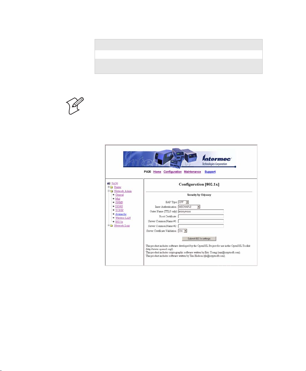
Chapter 3 — Configuring Communication Settings
Wireless LAN Settings Descriptions (continued)
Setting Description
WPA Pre-Shared Key Key value for the pre-shared key.
Roaming setting Leave at Level 1 unless the PA30 has trouble
maintaining a connection to the access point.
Changing 802.1x Security Settings
Note: Before you change security settings, you should be familiar
with the 802.1x security requirements for your wireless network.
For more information, consult your network administrator.
1 From the menu, click Network Admin > 802.1x. This screen
appears:
2 Choose settings from the drop-down lists, or enter values in
the entry fields. For more information, see the next table.
3 Click Submit 802.1x settings. The changes are saved.
60 PA30 Print Engine User’s Manual
Page 75

Chapter 3 — Configuring Communication Settings
802.1x Security Settings Descriptions
Setting Description
EAP Type Authentication type for the 802.1x client on
the PA30. Choose from:
•TTLS
•LEAP
•PEAP
• OFF to disable EAP authentication
Inner
Authentication
Outer Name
(TTLS only)
Root Certificate Name of the certificate containing the public
Server Common
Name #1
Server Common
Name #2
Server Certificate
Val id at io n
Inner authentication method for this 802.1x
client if you chose TTLS or PEAP as the EAP
type. Choose from:
•PAP
•MSCHAPv2
•EAP/MSCHAPv2
•EAP/MD5
•EAP/GTC
EAP identity passed in the clear if you selected
TTLS as the EAP Type. Default is
“anonymous”.
key corresponding to the private key used to
sign the server’s certificate. Default is /rom/
intermec.cer. To override this certificate, load
another certificate in .der, .cer, .p12, or .pfx
format.
Name that the common name on the server
certificate must match for authentication.
Default is blank (accepts any common name).
Name that the common name on the server
certificate must match for authentication.
Default is blank (accepts any common name).
If this name is specified, the server certificate
common name must match either this name or
Server Common Name #1.
When set to ON, requires that the installed CA
certificate is the root of the server certificate.
Default is ON.
PA30 Print Engine User’s Manual 61
Page 76

Chapter 3 — Configuring Communication Settings
62 PA30 Print Engine User’s Manual
Page 77

4
Configuring Print Engine and Media Settings
This chapter explains how to configure print engine and media
settings on the PA30, including:
• About Print Engine Settings: Changing the start and stop
adjust parameters, print speed, and enabling clip default.
• About Alert Messages: Configuring alert messages the PA30
sends during operation and error conditions.
• About Media Settings: Configuring the PA30 for specific
media types and setting the print window size. Includes
information on thermal transfer and direct thermal print
modes.
PA30 Print Engine User’s Manual 63
Page 78

Chapter 4 — Configuring Print Engine and Media Settings
About Print Engine Settings
Print engine settings determine the way the PA30 handles
printing and media.
This section explains how to use the web browser interface to
view and change print engine settings, including:
• Print speed, Start Adjust, and Stop Adjust values. For more
information, see the next section.
• Alert message settings, including the text of alert messages and
other related parameters. For more information, see “Ab ou t
Alert Messages” on page 66.
This chapter assumes you are using the web browser interface to
configure the PA30. For more information, see “Using the Web
Browser Interface” on page 30.
Configuring Print Engine Settings
Print engine settings apply to all printing regardless of the
application. These settings include:
• Start Adjust and Stop Adjust parameters, which determine
how much of the media is fed out and pulled back before and
after actual printing.
• Print speed (inches per second)
•Clip default
To configure print engine settings
1 Open a web browser interface to the PA30.
2 From the menu, click Printer > Print Engine. The
Configuration [Print Engine] screen appears:
64 PA30 Print Engine User’s Manual
Page 79
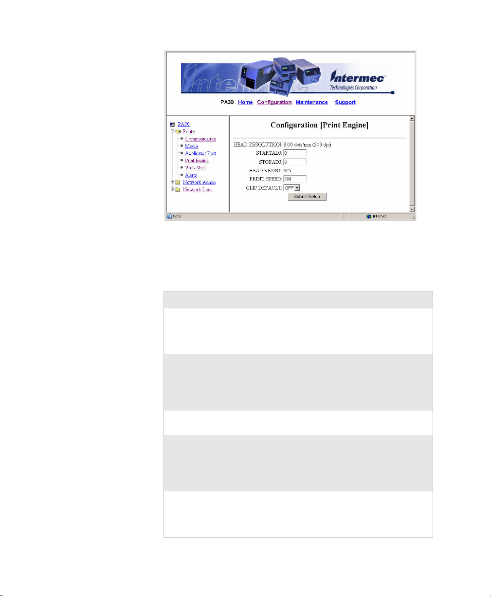
Chapter 4 — Configuring Print Engine and Media Settings
3 Enter values in the entry fields, or choose settings from the
drop-down lists. For more information, see the next table.
4 Click Submit Setup. The changes are saved.
Print Engine Settings Descriptions
Setting Description
STARTADJ
(Start Adjust)
STOPADJ
(Stop Adjust)
HEAD RESIST (Read-only) H
Amount of media (in dots) that is either fed out
or pulled back before printing begins. A positive
Start Adjust value feeds media out and a negative
value pulls media back. Default is 0.
Amount of media (in dots) that is fed out or
pulled back after printing is completed. A positive
Stop Adjust value increases the normal media feed
and a negative Stop Adjust value decreases the
normal media feed. Default is 0.
ead resistance value for the
installed printhead.
PRINT SPEED Sets the desired printing speed in inches per
second (ips). Set the print speed to a value
appropriate for your media. For more
information, see “Media Type Settings” on
page 71.
CLIP DEFAULT Enables or disables printing of partial fields.
Partial fields are print fields that have been
configured larger than the print window and will
be truncated if Clip Default is enabled.
PA30 Print Engine User’s Manual 65
Page 80

Chapter 4 — Configuring Print Engine and Media Settings
About Alert Messages
The PA30 firmware can send alert messages when certain
operating conditions or errors occur. You can use the web
browser interface to configure:
• the text for each alert message.
• the number of times the alert message is repeated.
• the amount of time or repeated errors that cause an alert
message to be repeated.
To configure alert message settings, see the next section.
You can also configure settings for the mail server where the alert
messages are sent. For more information, see “Configuring Mail
Settings” on page 68.
Configuring Alert Messages
1 Open a web browser interface to the PA30. For help, see
“Using the Web Browser Interface” on page 30.
2 From the menu, click Printer > Alerts. The Configuration
[Alerts] screen appears:
The Alerts screen shows a list of printer alert messages. Some
alert messages are sent when the error occurs, and some alert
messages are not sent until a PRINTFEED command is
executed. For more information on alert messages, see the
next table.
66 PA30 Print Engine User’s Manual
Page 81

Chapter 4 — Configuring Print Engine and Media Settings
3 For each alert you want to configure:
• Choose enabled or disabled from the Setting list for that
alert.
• Enter a value for the delay repeat in the Delay Repeat
entry field.
• Choose seconds or occurrences from the Delay unit
drop-down list.
• (Optional) Change the default alert message text in the
Message entry field.
4 Choose a notification method from the Notify with drop-
down list:
• Choose trap to send the mail notification to the SNMP
trap specified in SNMP settings. For more information,
see “Using Simple Network Management Protocol” on
page 99.
• Choose mail to send the notification to the E-mail address
specified in mail settings. For more information, see
“Configuring Mail Settings” on page 68.
• Choose trap and mail to send the notification to both the
SNMP trap and the E-mail address.
5 Click Submit Setup. The changes are saved.
Alert Message Descriptions
Message Sent When
Label Not Taken Printed label is not taken from the printer.
Requires the optional label taken sensor (LTS)
and applies to label and ticket media types.
Cutter Error Label cutter error occurs.
Head Lifted Print job is sent to the printer while the printhead
is lifted.
Out of Ribbon Thermal transfer ribbon is selected and the
printer is out of ribbon.
Out of Paper Printer is out of media.
Ribbon Low Diameter of the remaining roll of ribbon is lower
than the value specified in the Media
configuration screen.
PA30 Print Engine User’s Manual 67
Page 82

Chapter 4 — Configuring Print Engine and Media Settings
Alert Message Descriptions (continued)
Message Sent When
Pause Mode Print job is sent while the printer is paused.
Setup Mode Printer is in Setup mode.
Error Condition An error occurs in a running Fingerprint
application. Includes non-critical errors.
Application Break A running Fingerprint application is interrupted
manually or due to an error.
Print Job Complete Print job is successfully completed.
Odometer Count1 Amount of media printed reaches a set amount,
measured in meters or number of labels.
Configuring Mail Settings
Follow this procedure to specify mail settings, which determine
where alert messages are sent.
1 From the menu, click Network Admin > Mail. The
Configuration [Mail (SMTP)] screen appears:
68 PA30 Print Engine User’s Manual
Page 83

Chapter 4 — Configuring Print Engine and Media Settings
2 Choose an option:
• Click SMTP settings from DHCP if you want the
DHCP server to assign SMTP values.
• Click Manual settings to configure the mail server and
port manually, and then enter those values in the Mail
Server and Port entry fields.
3 (Optional) Enter mail address information in the From
address and To address entry fields.
4 Click Submit Mail settings. The changes are saved. You can
also click Submit & Send test mail to send a test mail
message to confirm your settings are working properly.
About Media Settings
These settings define the size and type of media you are using in
the PA30. This section explains media size and media type
settings. For best performance and print quality, make sure you
have configured these settings correctly.
To configure media settings, see “Configuring Media Settings”
on page 75.
Media Size Settings
The media size settings specify a “print window” inside which the
label is printed. Any object or field extending outside the print
window in any direction is clipped or causes a “field out of label”
error condition. For more information, see the Fingerprint
programmer’s reference manual.
PA30 Print Engine User’s Manual 69
Page 84

Chapter 4 — Configuring Print Engine and Media Settings
Printable area
max. 112 mm (4.41 in)
Dot #896 (203 dpi printhead)
Dot #1323 (300 dpi printhead)
Length
Dot #0
Media size
25 - 120 mm (1.0 - 4.72 in)
X-start
Width
Origin
Print window
Feed direction
Print Window Dimensions: This illustration shows the relationship of the
Xstart, Width, and Length settings to the media size and printable area.
Xstart
Specifies the position of the origin along the dots on the
printhead.
The default X-start value prevents printing outside labels when
the liner is slightly wider than the labels. If you want to maximize
the print width, reset the X-start value to 0.
By increasing the value for the X-start parameter, the origin will
be moved outwards, away from the inner edge of the media path.
In other words, the larger X-start value, the wider inner margin
and the less available print width.
70 PA30 Print Engine User’s Manual
Page 85

Chapter 4 — Configuring Print Engine and Media Settings
Width
Specifies the width of the print window (in number of dots) from
the origin. Thus, the sum of the X-start and width values gives
the outer margin of the print window. The width should be set to
prevent printing outside the media, which may harm the
printhead.
Length
Specifies the length of the print window (in number of dots)
from the origin along the Y-coordinate and allocates memory
space for two identical image buffers in the printer’s temporary
memory.
The size of each buffer can be calculated using this formula:
Buffer size (bits) = [Print length in dots] x [Printhead width in
dots]
Note: The temporary memory has other functions that also
require some memory space. To obtain a longer print area, you
can have more memory installed in the PA30. For more
information, contact your Intermec sales representative.
The length setting also decides the amount of media feed when
using “fix length strip.”
When the printer is set to use label or ticket stock, the length
setting creates an emergency stop if the label stop sensor has not
detected a gap or mark within 150% of the set length. Media feed
is automatically stopped to avoid feeding out a whole roll of
media because of a sensor malfunction.
Media Type Settings
These settings specify the type of media and related parameters.
Media Type
Specifies the media type being used, which also controls how the
label stop sensor (LSS) and the media feed work. There are five
media type options:
• Label (w gaps) is used for adhesive labels mounted on liner.
• Ticket (w mark) is used for labels or tickets with black marks
at the back.
• Ticket (w gaps) is used for tickets and tags with detection
slots.
PA30 Print Engine User’s Manual 71
Page 86

Chapter 4 — Configuring Print Engine and Media Settings
• Fix length strip is used for continuous stock where the length
of the print window decides the length of media to be fed out.
• Var length strip is used for continuous stock. The size of the
print images decides the length of each copy.
When you select the correct media type, the printer can indicate
the following errors:
• Error 1005 “Out of paper” indicates that the last ordered copy
could not be printed because of an empty media stock.
• Error 1031 “Next label not found” indicates that the last
ordered label or ticket was successfully printed, but no more
labels/tickets can be printed because of an empty media stock.
Paper Type
Specifies the printing mode:
• Thermal Transfer printing (default)
• Direct Thermal printing
This parameter controls the heat emitted from the printhead to
the ribbon or direct thermal media in order to produce the dots
that make up the print image.
For more information on thermal transfer printing, see “Thermal
Transfer Printing Settings” on page 73.
For more information on direct thermal printing, see “Direct
Thermal Print Settings” on page 74.
Contrast
Choose a contrast level for printing. Range is -10% to +10% in
10% intervals. Default is 0. Use this setting to make minor
adjustments of the blackness in the printout (for example, to
adapt the printer to variations in quality between different
batches of the same media). Contrast is reset to 0 whenever a new
paper type is specified.
Testfeed Mode
Sets the Testfeed mode to either fast or slow. Choose slow if you
are using media with preprinted lines.
72 PA30 Print Engine User’s Manual
Page 87

Chapter 4 — Configuring Print Engine and Media Settings
The sensitivity of the label stop sensor (LSS) may need to be
adjusted when switching from one type of media to another. This
is especially the case when using adhesive labels since the
transparency of the liner (backing paper) may vary. When the
Testfeed menu is displayed, press Enter on the PA30 front panel.
A number of blank copies are fed out until the firmware has
decided the proper setting for the LSS. At the same time, the
front edges of the labels, tickets, etc. are detected so the feed
control can position the media according to the Feedadjust
parameter (same as the Intermec Fingerprint statement
TESTFEED). Four values used for troubleshooting the LSS are
displayed (read-only information).
Len (Slow Mode)
Sets the length of the media sampled when Testfeed Mode is set
to slow. Default is the media length specified by the Length
parameter plus 10 mm. minimum value is the number of dots
corresponding to 10 mm.
Thermal Transfer Printing Settings
When you select thermal transfer printing, you need to specify
additional settings:
Ribbon Constant
Choose a value appropriate for the media you are using. For more
information, see the next table.
Ribbon Factor
Unless specified for your media, set to 25.
Label Offset
Always set to 0.
Low Diameter
Specifies the ribbon supply roll diameter (in mm) at which you
want the printer to send a “ribbon low” alert message. The
printer can detect this diameter to within ±3 mm. Default setting
is 0, effectively disabling this feature.
Adjusting Image Darkness
When adjusting the image darkness for non-Intermec media and
transfer ribbons:
• Set the Ribbon Factor to the recommended value as seen in
the next table.
PA30 Print Engine User’s Manual 73
Page 88

Chapter 4 — Configuring Print Engine and Media Settings
• Set the Ribbon Constant to the value listed in the table and
decrease or increase it for lighter or darker images respectively
until you are satisfied with the printout quality.
General Thermal Transfer Print Settings
Media
Performance
Low (Europe) 75 25 150
Low (U.S.A.) 70 25 150
Medium (Europe) 90 25 200
Medium (U.S.A.) 75 25 200
High (Europe) 90 25 225
High (U.S.A.) 90 25 225
Ribbon
Constant
As a general rule, high energy and/or high print speed will
shorten the life of the printhead. Never use paper type and print
speed settings higher than necessary for obtaining acceptable
printout quality and throughput speed.
If the ambient temperature is lower than +15°C (+59°F), decrease
the print speed by 50 mm/sec.
Ribbon
Fac tor
Maximum
Print Speed
(ips)
Direct Thermal Print Settings
When you select direct thermal printing, you also need to specify
these additional settings:
Label Constant
Choose a value appropriate to the type of media you are using.
For more information, see the next table.
Label Factor
Unless specified for your media, set to 40.
Adjusting Image Darkness
When adjusting the image darkness for non-Intermec direct
thermal media:
• Set the Label Factor to the recommended value for the type of
direct thermal media listed in the next table.
74 PA30 Print Engine User’s Manual
Page 89

Chapter 4 — Configuring Print Engine and Media Settings
• Set the Label Constant to the value listed in the table.
Decrease or increase it for lighter or darker images respectively
until you are satisfied with the printout quality.
General Direct Transfer Print Settings
Sensitivity
Low 100 40 100
Standard 90 40 150
High 80 40 200
Ultra high 60 40 225
Note: Preprint and varnish decrease the sensitivity of direct
thermal media.
Configuring Media Settings
Follow the next procedure to configure media size and type
settings for the PA30.
Label
Constant
Label
Fac tor
Maximum
Print Speed
(ips)
To configure media size and type
1 From the menu, click Printer > Media. The Configuration
[Media] screen appears.
PA30 Print Engine User’s Manual 75
Page 90

Chapter 4 — Configuring Print Engine and Media Settings
2 Choose settings from the drop-down lists, or enter settings in
the entry fields.
• For information on Xstart, Width, and Length settings,
see “Media Size Settings” on page 69.
• For information on all other settings, see “Media Type
Settings” on page 71.
3 Click Submit Setup. The settings are saved.
76 PA30 Print Engine User’s Manual
Page 91

5
This chapter explains how to use Setup mode to configure the
PA30. In Setup mode, you use the printer keypad and display to
view and change settings.
• About Setup Mode describes what Setup mode is, how to
• Setup Mode Menus includes illustrations of the Setup mode
Using Setup Mode
place the PA30 in Setup mode and navigate in the menus, and
includes lists of the settings you can configure in Setup mode.
menus as a visual reference.
PA30 Print Engine User’s Manual 77
Page 92

Chapter 5 — Using Setup Mode
Right arrow
Left arrow
Up arrow
Down arrow
About Setup Mode
In Setup mode, you can use the PA30 keypad and display to view
and change configuration settings.
Placing the PA30 in Setup Mode
There are three ways to place the PA30 in Setup mode:
•Press Setup on the PA30 front panel.
• From the Intermec Shell program, press the left or right arrow
keys to choose SHELL SETUP and press Enter.
• Send the Fingerprint SETUP command from a host PC.
When the PA30 is in Setup mode, this text appears in the display:
Navigating in Setup Mode
When the PA30 is in Setup mode, you use the arrow keys to
navigate between menus and options.
• Press the right arrow key several times to cycle through the
settings menus. Press the left arrow key several times to cycle
through the menus in the opposite direction.
• Press the down arrow key to enter a settings menu and see the
first option for that setting. Press the right arrow key several
times to cycle through the options for that setting.
• To choose an option, press Enter.
• If the setting requires a value, press the left and right arrow
keys to select a digit in that value. Press the numeric keys
to enter values. When you finish setting the value, press
Enter. The next setting in that menu appears.
78 PA30 Print Engine User’s Manual
Page 93

Note: Read-only settings appear in brackets.
What Settings Can You Configure in Setup Mode?
In Setup mode, you can configure most basic PA30 settings,
including serial and network communication, applicator port,
media parameters, and print engine settings such as feed adjust.
The next section lists the PA30 settings you can configure in
Setup mode.
Note: Some PA30 settings can only be configured through the
web browser interface or by sending Fingerprint commands to the
printer.
Serial Communication Settings
•Baud rate
•Character length
•Parity
•Stop bits
Chapter 5 — Using Setup Mode
• Flow control
•New line
• Receiver buffer
•Transmit buffer
For more information on these settings, see “Serial
Communication Settings” on page 51.
Network Communication Settings
• IP selection (DHCP, BOOTP, combination, or manual)
• IP address (if manually configured)
•Netmask
• Default router
• Nameserver
• MAC address (read-only)
PA30 Print Engine User’s Manual 79
Page 94

Chapter 5 — Using Setup Mode
For more information on these settings, see “TCP/IP Settings
Descriptions” on page 53.
Note: You cannot change wireless network settings or security
settings in Setup mode. For more information, see “Configuring
Wireless Network Settings” on page 58.
Feed Adjust Settings
•Start adjust
•Stop adjust
For more information, see “About Print Engine Settings” on
page 64.
Media Size and Media Type Settings
•Xstart
•Width
•Length
•Media type
• Paper type, including specific settings for thermal transfer and
direct thermal printing
•Contrast
• Testfeed (Read-only)
• Testfeed mode
•Len (slow mode)
For more information on these settings, see “Configuring Media
Settings” on page 75.
Print Define Settings
• Print speed and clip default. For more information on these
settings, see “Print Engine Settings Descriptions” on
page 65.
• Testprint, which chooses the default test label. Press Enter to
print the selected test label. For more information on test
labels, see “Printing Test Labels and Setup Information” on
page 96.
• LSS test, which sets the label stop sensor mode. For more
information, see “Testing the Label Stop Sensor” on page 29.
80 PA30 Print Engine User’s Manual
Page 95
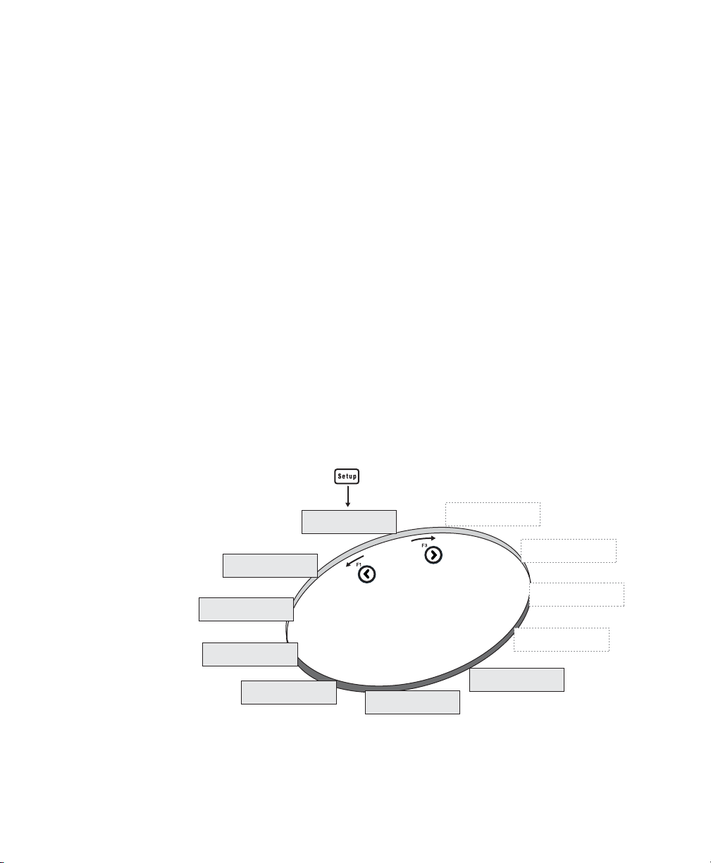
Applicator Port Settings
SETUP:
SER-COM, UART1
SETUP:
PRINT DEFS
SETUP:
MEDIA
SETUP:
FEEDADJ
SETUP:
NETWORK
SETUP:
NET-COM, NET1
SETUP:
SER-COM, UART3
SETUP:
SER-COM, UART4
SETUP:
SER-COM, UART5
SETUP:
SER-COM, UART2
Starting point
SETUP:
APPLICATOR PORT
• Status
•Style
•Power source
•In signals
•Out signals
• Relay signals
For more information on these settings, see “Configuring
Applicator Port Settings” on page 34.
Setup Mode Menus
The menus in Setup mode are organized as a loop from which
you can choose individual settings and options for each setting.
At startup, the firmware determines which hardware options are
installed in the print engine and shows the appropriate menus for
those options in Setup mode.
This section includes illustrations that show how the Setup mode
menus are organized. To move from one menu to the next, press
the left or right arrow keys.
Chapter 5 — Using Setup Mode
Setup Mode: This illustration shows the order in which menus appear in
Setup mode. Menus in gray dotted lines appear only if your PA30 includes
those hardware options.
PA30 Print Engine User’s Manual 81
Page 96

Chapter 5 — Using Setup Mode
Continue to
For all serial communications settings, press to cycle through the options.
Continued from
Continue to
Cycle
options
Cycle
options
Serial Communication Settings
Network Communication Settings
82 PA30 Print Engine User’s Manual
Page 97

Feed Adjust Settings
Continued from
Continue to
Continue to
Cycle
options
Continued from
Cycle
options
Media Settings
Chapter 5 — Using Setup Mode
PA30 Print Engine User’s Manual 83
Page 98

Chapter 5 — Using Setup Mode
Continue to
Continued from
Cycle
options
Press Enter to print
Press i for error info
Toggle between
gain (G) and drive (D)
Decrease/increase value
inside brackets
Print Definition Settings
84 PA30 Print Engine User’s Manual
Page 99

Applicator Port Settings
Continue to
Continued from
Continue to
APPLICATOR PORT:APPLICATOR PORT:
POWER SOURCEPOWER SOURCE
on next page
For all applicator port settings, press to cycle through the options.
Chapter 5 — Using Setup Mode
PA30 Print Engine User’s Manual 85
Page 100

Chapter 5 — Using Setup Mode
POWER SOURCE:POWER SOURCE:
DC 5VDC 5V
POWER SOURCE:POWER SOURCE:
DC 24VDC 24V
DC 5V:DC 5V:
INTERNALINTERNAL
EXTERNALEXTERNAL
DC 24V:DC 24V:
INTERNALINTERNAL
EXTERNALEXTERNAL
APPLICATOR PORT:APPLICATOR PORT:
POWER SOURCEPOWER SOURCE
Continued from
Applicator Port Settings (continued)
86 PA30 Print Engine User’s Manual
 Loading...