


 Operation Manual
Reference Amplifier
R150 PLUS/300 PLUS/500 PLUS
* Rack mount products in the Western Hemisphere(North America, South America, and the Caribbean) do not have handles installed due to customer preference.

E n g l i s h
REFERENCE AMPLIFIER
Contents |
|
Welcome |
|
Warning......................................................................................................................................... |
1 |
Unpacking ...................................................................................................................................... |
2 |
Short Form Instructions..................................................................................................................... |
2 |
Installation |
|
Environment.................................................................................................................................... |
3 |
Important Safety Instructions............................................................................................................. |
3 |
Description....................................................................................................................................... |
4 |
Features............................................................................................................................................ |
4 |
Accessories..................................................................................................................................... |
4 |
Front Panel ...................................................................................................................................... |
5 |
Rear Panel ....................................................................................................................................... |
6 |
Mounting in a Rack........................................................................................................................ |
7 |
Applications |
|
Stereo Installation ............................................................................................................................ |
8 |
Bridge Mono Installation .................................................................................................................. |
9 |
Linked Installation.......................................................................................................................... |
10 |
Connections ................................................................................................................................... |
11 |
Block Diagram .............................................................................................................................. |
13 |
Specifications ................................................................................................................................ |
14 |
Service |
|
Procedures.................................................................................................................................... |
15 |
Schematic ..................................................................................................................................... |
15 |
Parts List ....................................................................................................................................... |
15 |
Variations and Options ............................................................................................................... |
15 |
Warranty ....................................................................................................................................... |
15 |
REFERENCE AMPLIFIER
Wellcome
A personal welcome to you from the management and employees of Inter-M
All of the co-workers here at Inter-M are dedicated to providing excellent products with inherently good value, and we are delighted you have purchased one of our products.
We sincerely trust this product will provide years of satisfactory service, but if anything is not to your complete satisfaction, we will endeavor to make things right.
Welcome to Inter-M, and thank you for becoming part of our worldwide extended family!
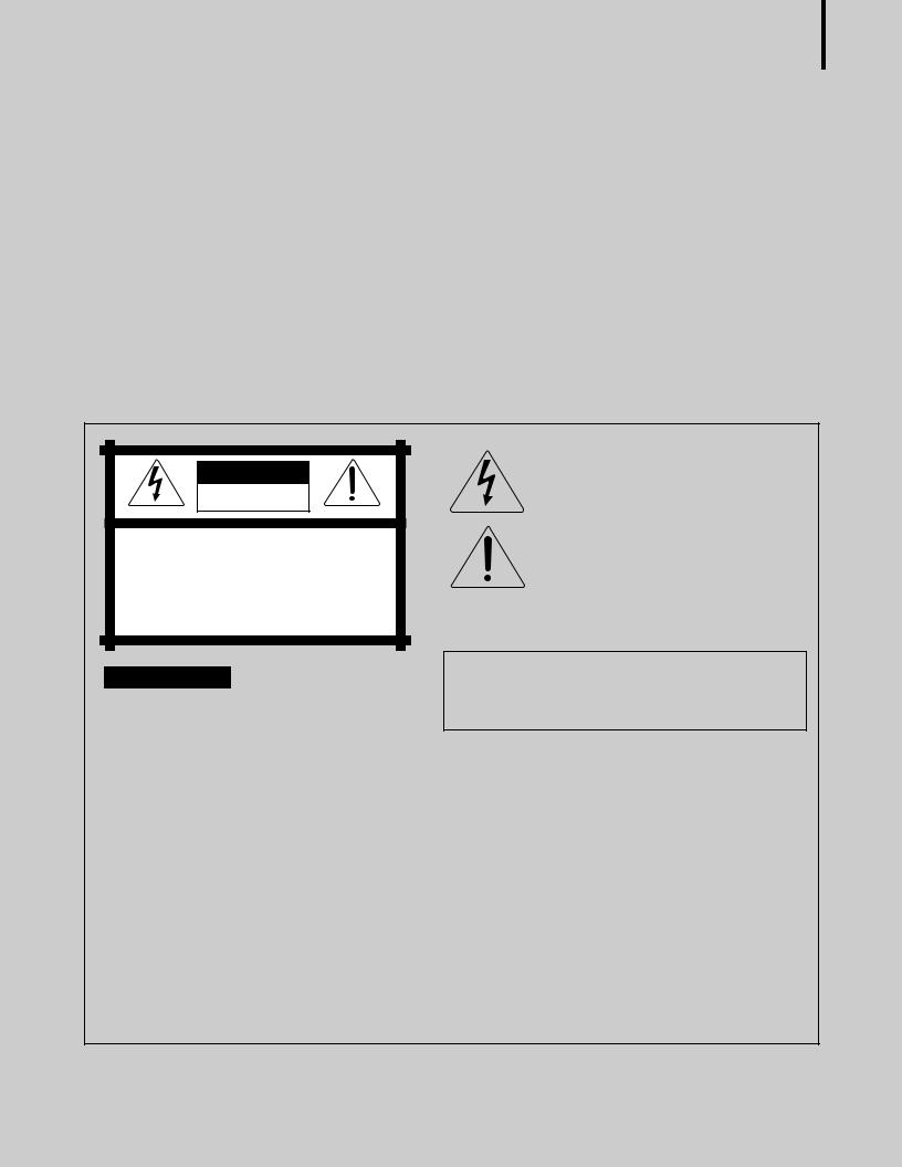
CAutION
RISK OF ELECTRIC SHOCK
DO NOT OPEN
CAUTION: TO REDUCE THE RISK OF ELECTRIC SHOCK.
DO NOT REMOVE COVER (OR BACK).
NO USER-SERVICEABLE PARTS INSIDE.
REFER SERVICING TO QUALIFIED SERVICE PERSONNEL.
WARNING
To prevent fire or shock hazard, do not expose the unit to rain or moisture.
This symbol is intended to alert the user to the presence of uninsulated “dangerous voltage” within the product’s enclosure that may be of sufficient magnitude to constitute a risk of electric shock to persons.
This symbol is intended to alert the user to the presence of important operation and maintenance (servicing) instructions in the literature accompanying the appliance.
Caution: To prevent electric shock do not use this (polarized) plug with an extension cord, receptacle or other outlet unless the blades can be fully inserted to prevent blade exposure.
Attentions: Pour prévenir les chocs électriques ne pas utiliser cette fiche polarisée avec un prolongateur, une prise de courant on une autre sortie de courant, sauf si les lames peuvent étre insérées à fond sans en laisser aucune partie à découvert.
*WARNING FOR YOUR PROTECTION PLEASE READ THE FOLLOWING-WATER AND MOISTURE: Unit should not be used near water(e.g. near a bathtub, washbowl, kitchen sink, laundry tub, in a wet basement, or near a swimming pool, etc). Care should be taken so than objects do not fall and liquids are not spilled into the enclosure through openings.
*CLASS 2 WIRING (Adjacent to speaker terminal): The speaker output of this apparatus can exceed 10 Watts and could be a shock injury. Connection to speakers should be performed by a skilled person.
*Do not install this equipment in a confined space such as a book case or similar unit.
*This apparatus shall not be exposed to dripping or splashing and no objects filled with liquids, such vases, shall be placed on the apparatus. *This apparatus shall be connected to a mains socket outlet with a protective earthing connection.
*It has heed to be easy to disconnect the device. To disconnect the device from power, separate AC input cable from inlet or unplug the AC Cord.
CAutION
*These servicing instructions are for use by qualified service personnel only. To reduce the risk of electric shock, do not perform any servicing other than that contained in the operating instructions unless you are qualified to do so.
NOtE
*This equipment has been tested and found to comply with the limits for a Class A digital device, pursuant to Part 15 of the FCC Rules. These limits are designed to provide reasonable protection against harmful interference when the equipment is operated in a commercial environment. This equipment generates, uses, and can radiate radio frequency energy and, if not installed and used in accordance with the instruction manual, may cause harmful interference to radio communications. Operation of this equipment in a residential area is likely to cause harmful interference in which case the user will be required to correct the interference at his own expense.
h s i l g n E
R150 PLUS/300 PLUS/500 PLUS |
1 |

REFERENCE AMPLIFIER
Unpacking
Please take a few minutes to read this manual to familiarize yourself with important information regarding installation, product features, and operation.
As with most electronic devices, ORIGINAL PACKAGING (OR EQUAL) IS REQUIRED in the unlikely event that the product needs to be returned for servicing.
Short Form Instructions
|
1. |
Do not connect the AC power until step 6. The POWER switch should be in the OFF position. |
|
2. |
Adjust both of the LEVEL controls to the fully attenuated position (turn counter-clockwise). |
s h |
3. Connect an appropriate line level input signal to either the balanced XLR or the balanced 1/4" TRS (Tip-Ring- |
|
|
Sleeve) connector marked INPUTS. |
|
g l i |
4. Move the MODE selector to the desired position. The Stereo position is the most common. |
|
E n |
5. |
Connect the OUTPUTS to the speaker load according to the mode of operation determined in the previous step. |
|
||
|
6. With the power switch in the OFF position, plug in the supplied Universal AC power cord to the product and |
|
|
|
an appropriate AC source. |
|
7. |
Depress the power switch to the ON position. The power switch will illuminate. |
|
8. |
The product is ready for operation. Slowly increase the LEVEL control to the desired operating level. Avoid |
|
|
illuminating the PEAK indicator and do not apply too much power to the speakers. |
|
9. |
Operate the product and the system in a manner which DOES NOT illuminate the PEAK warning indicator. |
2 R150 PLUS/300 PLUS/500 PLUS

REFERENCE AMPLIFIER
IInsttallllatition
Environment
Never place this product in an environment which could alter its performance or reduce its service life. Such environments usually include high levels of heat, dust, moisture, and vibration.
IMPORTANT SAFETY INSTRUCTIONS
1. |
Read these instructions. |
|
2. |
Keep these instructions. |
|
3. |
Heed all warnings. |
|
4. |
Follow all instructions. |
|
5. |
Do not use this apparatus near water. |
|
6. |
Clean only with dry cloth. |
|
7. |
Do not block any ventilation openings. Install in accordance with the manufacturer’s instructions. |
n E |
8. |
Do not install near any heat sources such as radiators, heat registers, stoves, or other apparatus (including |
|
|
amplifiers) that produce heat. |
g |
9. |
Do not defeat the safety purpose of the polarized or grounding-type plug. A polarized plug has two blades |
i l |
|
with one wider than the other. A grounding type plug has two blades and a third grounding prong. The wide |
s |
|
blade or the third prong are provided for your safety. If the provided plug does not fit into your outlet, consult |
h |
an electrician for replacement of the obsolete outlet.
10. Protect the power cord from being walked on or pinched particularly at plugs, convenience receptacles, and the point where they exit from the apparatus.
11. Only use attachments/accessories specified by the manufacturer.
12. Use only with the cart, stand, tripod, bracket, or table specified by the manufacturer, or sold with the apparatus. When a cart is used, use caution when moving the cart/apparatus combination to avoid injury from tip-over.
13. Unplug this apparatus during lightning storms or when unused for long periods of time.
14. Refer all servicing to qualified service personnel. Servicing is required when the apparatus has been damaged in any way, such as power-supply cord or plug is damaged, liquid has been spilled or objects have fallen into the apparatus, the apparatus has been exposed to rain or moisture, does not operate normally, or has been dropped.
S3125A
S3125A
R150 PLUS/300 PLUS/500 PLUS |
3 |

E n g l i s h
REFERENCE AMPLIFIER
Descriiptition
-R150 PLUS
A 2U rack space, 2 channel amplifier capable of 150W into 8Ω load (bridged mono).
-R300 PLUS
A 2U rack space, 2 channel amplifier capable of 300W into 8Ω load (bridged mono).
-R500 PLUS
A 2U rack space, 2 channel amplifier capable of 500W into 8Ω load (bridged mono).
Feattures
-4Ω stable per channel (stereo), 8Ω stable (bridge mono)
-2U rack space
-Front panel indicators for signal strength, clip, protect, and power
-Rack Ears for permanent installation in a standard 19” (rack mount width) enclosure.
-Detachable AC power cord
Accessories
One detachable AC power cord is provided for use with this product.
4 R150 PLUS/300 PLUS/500 PLUS
REFERENCE AMPLIFIER
t |
l |
|
|
|
|
|
|
|
|
|
|
|
|
Front Panel |
|
|
|
|
|
|
|
|
|
|
|
|
|
|
1 |
2 3 4 |
|
|
|
|
|
5 |
6 |
7 |
|||
|
12 |
11 10 |
9 |
8 |
|
|
12 11 10 |
9 |
8 |
|
LUS |
POWER |
|
|
13 |
|
|
7 |
|
|
13 |
|
7 |
|
|
|
|
|
15 |
|
|
6 |
|
|
15 |
|
6 |
|
|
|
|
|
17 |
|
|
5 |
|
|
17 |
|
5 |
|
ON |
|
|
|
19 |
|
|
4 |
|
|
19 |
|
4 |
|
R E F E R E N C E A M P L I F I E R |
|
|
|
22 |
|
|
3 |
SIG |
CLIP PROT |
22 |
|
3 |
SIG CLIP PROT |
P |
|
|
|
29 |
|
|
2 |
29 |
|
2 |
POWER |
|
|
|||
|
54 |
|
|
0 1 |
|
|
54 |
|
0 1 |
|
|
OFF |
|
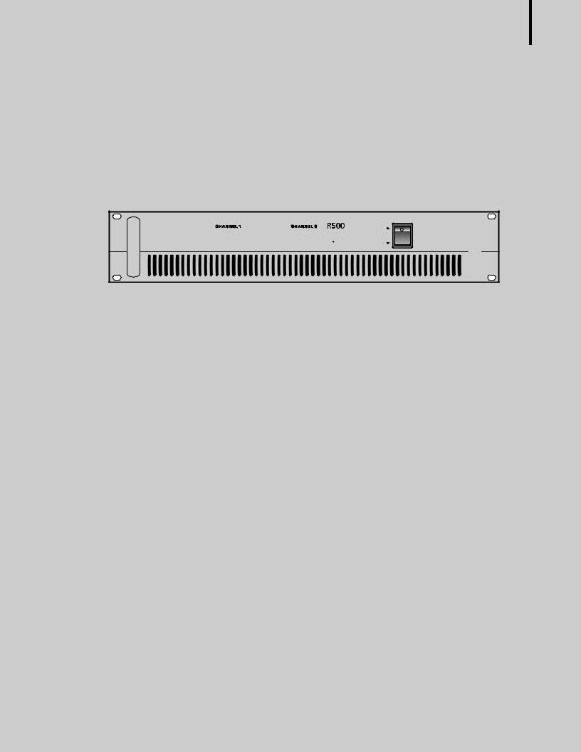
1. LEVEL CONTROL |
|
|
|
|
|
|
|
|
|
|
|
h s i l g n E |
|
|
This determines the level of the input signal for each channel. In stereo mode the knobs will determine the signal level |
||||||||||||
|
independently for each channel. In the bridge mono mode only the channel 1 level control is used. |
|
|||||||||||
2. SIGNAL INDICATOR
This indicates the level of the input signal. This should be illuminated during normal operation.
3. CLIP INDICATOR
This LED warns of a problem in the system when illuminated. Reduce the LEVEL of the device which supplies signal to the amplifier or reduce the LEVEL control(s) on the amplifier. This LED should not be illuminated during normal operation.
4. PROTECTION INDICATOR
This LED warns of a problem in the system when illuminated. Reduce the volume and look for problems. It is possible that the amplifier is too hot or the speaker impedance is too low. This LED should not be illuminated during normal operation.
5. POWER INDICATOR
This LED indicates the amplifier is switched ON and receiving AC POWER when illuminated.
6. POWER SWITCH
The position of this switch determines whether the power is ON or OFF. The power-on status is confirmed by the power indicator. Amplifiers are always the last item in a system to be turned on. It is a good idea to turn down the level controls before applying AC mains power.
7. HANDLE
Handles are provided for moving and installing into equipment enclosures or racks.
R150 PLUS/300 PLUS/500 PLUS |
5 |
E n g l i s h
REFERENCE AMPLIFIER
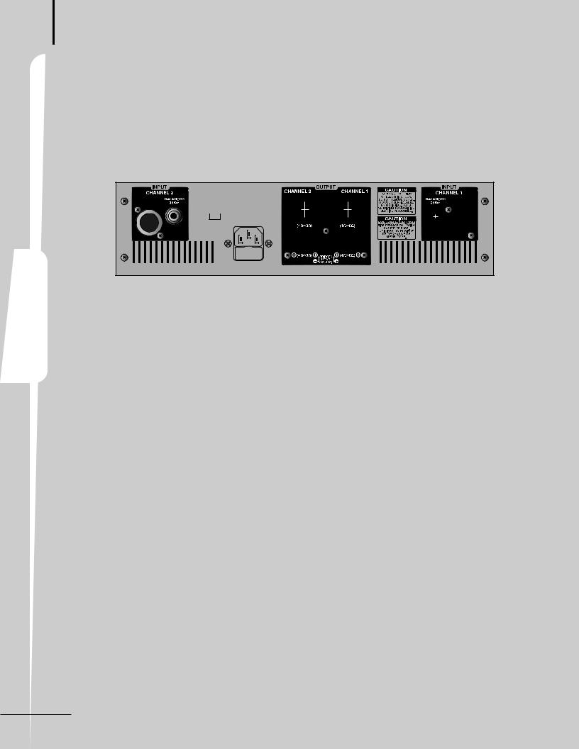
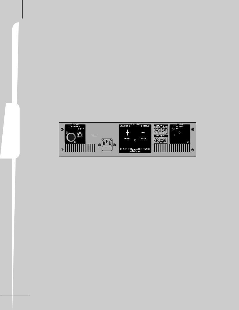
Rear Panell
1. BALANCED INPUT CONNECTORS
Each input channel is equipped with a 1/4" TRS and an XLR connector. Standard rules of interconnect apply.
2. MODE SELECTOR SWITCH
Move this switch to select either the STEREO or BRIDGED MONO position as needed for the application.
The Stereo mode is most common. Channel 1 input feeds the channel 1 output. The channel 2 input feeds the channel 2 output.
The Bridge Mono mode combines both channels to create one larger mono channel. Input signal applied to channel 1 will be available across the positive terminals of Channel 1 and channel 2. Do not connect the channel 2 input or any of the negative outputs.
3. OUTPUT CONNECTORS
Binding Posts and Locking speaker connectors are provided. Bridged Mono operation requires a different method of connecting the cables than Stereo operation. Be sure than the amplifier is in the correct mode before connecting the speaker load.
4. FUSE
The fuse protects the amplifier by opening the circuit for the AC mains power in case of overload or malfunction. If the fuse opens, the amplifier (and the various other components in the system) should be checked for proper operation. If the fuse continues to open after verifying that the system is wired correctly and that an overload has not occurred, the amplifier should be checked for proper operation by a service technician.
5. AC INPUT
Connect this product to an appropriate AC power source using the supplied Universal AC Power Cord.
6 R150 PLUS/300 PLUS/500 PLUS
REFERENCE AMPLIFIER
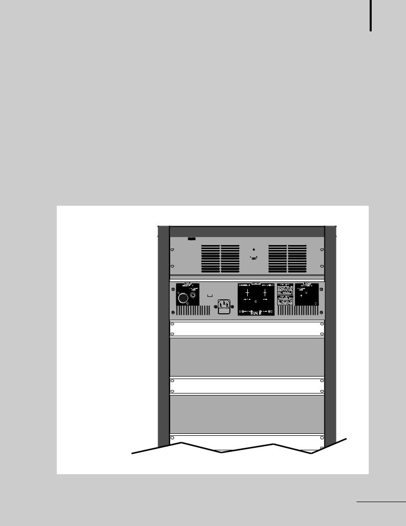
Mountiting iin a Rack
If multiple high-power amplifiers are mounted in a rack with poor ventilation, the heat from the amplifiers will cause the interior of the rack (and the amplifiers) to become very hot, which may cause problems with amplifier performance. If amplifiers are mounted in a rack without an open rear, you should use special care to help ensure proper ventilation of the rack.
Here are suggestions to help keep the amplifiers properly ventilated:
1.Leave a space of at least 10 cm (4 inches) between the rear door of the rack and the rear panel of the amplifier.
2.Install a fan or blower in the rack to help cool the equipment.
3.Install blank (or vent) panels between amplifiers.
Typical Rack with multiple amplifiers |
|
|
s i l g n E |
|
|
|
|
PF-9302 |
AUTO BLOWER |
|
h |
|
|
|
|
|
POWER LED |
|
|
Auto Blower(PF-9302) |
OFF MANUAL |
AUTO |
|
|
|
||
R150 PLUS/300 PLUS/500 PLUS |
|
|
|
Blank Panel |
|
|
|
R150 PLUS/300 PLUS/500 PLUS |
|
|
|
Blank Panel |
|
|
|
R150 PLUS/300 PLUS/500 PLUS |
|
|
|
|
R150 PLUS/300 PLUS/500 PLUS |
7 |
|
REFERENCE AMPLIFIER
Applilicatitions-1
STEREO INSTALLATION |
E n g l i s h |
8 R150 PLUS/300 PLUS/500 PLUS |
REFERENCE AMPLIFIER
Applilicatitions-2
BRIDGED MONO INSTALLATION |
|
|
h s i l g n E |
R150 PLUS/300 PLUS/500 PLUS |
9 |
 Loading...