


 Operation Manual
Mixing Amplifier
PMU-60N/120N/240N
MIXING AMPLIFIER
Welcomel
A personal welcome to you from the management and employees of Inter-M
All of the co-workers here at Inter-M are dedicated to providing excellent products with inherently good value, and we are delighted you have purchased one of our products.
We sincerely trust this product will provide years of satisfactory service, but if anything is not to your complete satisfaction, we will endeavor to make things right.
Welcome to Inter-M, and thank you for becoming part of our worldwide extended family!
CAUTION
RISK OF ELECTRIC SHOCK
DO NOT OPEN
CAUTION: TO REDUCE THE RISK OF ELECTRIC SHOCK.
DO NOT REMOVE COVER (OR BACK).
NO USER-SERVICEABLE PARTS INSIDE.
REFER SERVICING TO QUALIFIED SERVICE PERSONNEL.
WARNING
To prevent fire or shock hazard, do not expose the unit to rain or moisture.
This symbol is intended to alert the user to the presence of uninsulated “dangerous voltage” within the product’s enclosure that may be of sufficient magnitude to constitute a risk of electric shock to persons.
This symbol is intended to alert the user to the presence of important operation and maintenance (servicing) instructions in the literature accompanying the appliance.
Caution: To prevent electric shock do not use this (polarized) plug with an extension cord, receptacle or other outlet unless the blades can be fully inserted to prevent blade exposure.
Attentions: Pour prévenir les chocs électriques ne pas utiliser cette fiche polarisée avec un prolongateur, une prise de courant on une autre sortie de courant, sauf si les lames peuvent étre insérées à fond sans en laisser aucune partie à découvert.
*WARNING FOR YOUR PROTECTION PLEASE READ THE FOLLOWING-WATER AND MOISTURE: Unit should not be used near water(e.g. near a bathtub, washbowl, kitchen sink, laundry tub, in a wet basement, or near a swimming pool, etc). Care should be taken so than objects do not fall and liquids are not spilled into the enclosure through openings.
*CLASS 2 WIRING (Adjacent to speaker terminal): The speaker output of this apparatus can exceed 10 Watts and could be a shock injury. Connection to speakers should be performed by a skilled person.
*Do not install this equipment in a confined space such as a book case or similar unit.
*This apparatus shall not be exposed to dripping or splashing and no objects filled with liquids, such vases, shall be placed on the apparatus. *This apparatus shall be connected to a mains socket outlet with a protective earthing connection.
*It has heed to be easy to disconnect the device. To disconnect the device from power, separate AC input cable from inlet or unplug the AC Cord.
CAUTION
*These servicing instructions are for use by qualified service personnel only. To reduce the risk of electric shock, do not perform any servicing other than that contained in the operating instructions unless you are qualified to do so.
NOTE
*This equipment has been tested and found to comply with the limits for a Class A digital device, pursuant to Part 15 of the FCC Rules. These limits are designed to provide reasonable protection against harmful interference when the equipment is operated in a commercial environment. This equipment generates, uses, and can radiate radio frequency energy and, if not installed and used in accordance with the instruction manual, may cause harmful interference to radio communications. Operation of this equipment in a residential area is likely to cause harmful interference in which case the user will be required to correct the interference at his own expense.

MIXING AMPLIFIER
Contents |
|
|
Unpacking ....................................................................................................................................... |
2 |
|
Installation |
|
|
Environment.................................................................................................................................... |
2 |
|
Important Safety Instructions............................................................................................................. |
2 |
|
Features............................................................................................................................................ |
3 |
|
Operation ........................................................................................................................................ |
3 |
|
Front Panel ...................................................................................................................................... |
4 |
|
Rear Panel ....................................................................................................................................... |
9 |
|
Speaker Connection..................................................................................................................... |
12 |
|
System Connection....................................................................................................................... |
14 |
|
Block Diagram .............................................................................................................................. |
15 |
|
Specifications ................................................................................................................................ |
16 |
|
Web Setting................................................................................................................................... |
18 |
|
1. |
Accessing PMU-N Series Web-page........................................................................................... |
18 |
2. |
Network Setting ........................................................................................................................ |
18 |
3. |
Operation Mode Setting ............................................................................................................ |
19 |
4. |
Internet Radio Setting................................................................................................................. |
19 |
5. |
AOE Stream Setting................................................................................................................... |
20 |
6. |
Time Setting .............................................................................................................................. |
20 |
7. |
Log View .................................................................................................................................. |
21 |
8. |
Upgrade................................................................................................................................... |
21 |
9. |
Rebooting ................................................................................................................................. |
22 |
10. Factory Setting ........................................................................................................................ |
22 |
|
11. Password Setting ..................................................................................................................... |
23 |
|
Service |
|
|
Procedures.................................................................................................................................... |
24 |
|
Schematic..................................................................................................................................... |
24 |
|
Parts List ....................................................................................................................................... |
24 |
|
Variations and Options ............................................................................................................... |
24 |
|
Warranty ....................................................................................................................................... |
24 |
|
|
PMU-60N/120N/240N |
1 |

MIXING AMPLIFIER
Unpackingi
Although your PMU-60N/120N/240N is neither complicated nor difficult to operate, we recommend you take a few minutes to read this brief manual and familiarize yourself with the important information regarding product features, setup and operation.
As with most electronic devices, we strongly recommend you retain the original packaging. In the unlikely event the product must be returned for servicing, the original packaging (or reasonable equivalent) is required.
InstallationI ll i
Environment
Never place this product in an environment which could alter its performance or reduce its service life. Such environments usually include high levels of heat, dust, moisture, and vibration.
IMPORTANT SAFETY INSTRUCTIONS
1.Read these instructions.
2.Keep these instructions.
3.Heed all warnings.
4.Follow all instructions.
5.Do not use this apparatus near water.
6.Clean only with dry cloth.
7.Do not block any ventilation openings. Install in accordance with the manufacturer’s instructions.
8.Do not install near any heat sources such as radiators, heat registers, stoves, or other apparatus (including amplifiers) that produce heat.
9.Do not defeat the safety purpose of the polarized or grounding-type plug. A polarized plug has two blades with one wider than the other. A grounding type plug has two blades and a third grounding prong. The wide blade or the third prong are provided for your safety. If the provided plug does not fit into your outlet, consult an electrician for replacement of the obsolete outlet.
10.Protect the power cord from being walked on or pinched particularly at plugs, convenience receptacles, and the point where they exit from the apparatus.
11.Only use attachments/accessories specified by the manufacturer.
12.Use only with the cart, stand, tripod, bracket, or table specified by the manufacturer, or sold with the apparatus. When a cart is used, use caution when moving the cart/apparatus combination to avoid injury from tip-over.
13.Unplug this apparatus during lightning storms or when unused for long periods of time.
14.Refer all servicing to qualified service personnel. Servicing is required when the
apparatus has been damaged in any way, such as power-supply cord or plug is damaged, liquid has been spilled or objects have fallen into the apparatus, the apparatus has been exposed to rain or moisture, does not operate normally, or has been dropped.
S3125A
2 PMU-60N/120N/240N

MIXING AMPLIFIER
Featurest
-USB mp3 Player
-USB Audio Stream
-Internet Radio
-Stream Receiver from AOE-212N
-2.8" Color TFT LCD
-2U Size
-60W /120W /240W output power
-SMPS delivers high power output with low power consumption and weight reduction
-5 Microphone/Line Inputs, EXT IN and TELL IN with individual volume control
-Input Level LED Monitor per channel
-Separate BASS/TREBLE Tone Controls
-5 zone selection switches
-Independent built-in Attenuator over Zone 5 (70v/50V)
-PRIORITY
-Remote MUTE and CHIME terminal
-VCA Remote volume controll
Operationti
1.Make sure the power switch on the front of the unit is set to off and connect the power cord to the mains outlet. Please set each input volume control to minimum position and set the tone controls to 0dB before turning on the power switch.
2.Make sure the speaker cables and input cables are properly connected
3.Before connecting power, always check the voltage of main power supply (AC 220V or AC 110V)
4.After completing all connections, turn on the power switch, and check to confirm that the power indicator lights.
5.Use input level control for corresponding to desired mixing volume levels and set the output level with master volume control
6.Use the Treble/Bass tone controls to change the tone of the output source.
PMU-60N/120N/240N 3
MIXING AMPLIFIER
Frontt Panell
1. INPUT LEVEL CONTROL
Controls the level of each of the six input channels.
2. INPUT SIGNAL INDICATOR
These LEDs light green when input signal is present.
3. CHIME SWITCH
It activates the four tone chime circuitry. The chime indicator lights green when chime is on use.
4.ROTARY ENCODER CONTROL PROGRAM SELECTION DISPLAYED ON THE LCD DISPLAY
-SELECT
The select button activates MENU mode when pressed and held for a few seconds, then it is used as the select button during menu navigation.
-ESC
It used to return to the OPERATION MODE from the MENU MODE
5.TONE CONTROL
Controls the bass (100Hz) and treble (10KHz) tones of the main amplifier output.
4 PMU-60N/120N/240N
MIXING AMPLIFIER
6. PROTECTION MODE INDICATOR
Indicated that the amplifier is in failure protection mode.
7. MASTER VOLUME CONTROL
The master volume control to collectively control the sound level of all outputs and by turning the knob clockwise to increase the volume and counterclockwise to decrease it.
8.POWER SWITCH
9.POWER INDICATOR
This LED Lights green when the unit is powered on.
10. ATTENUATOR
Built-in ATTENUATOR over zone 5, It allows to decrease the output volume independently from master volume.
-Switch mode 1 : 100V output
-Switch mode 2 : 70V output
-Switch mode 3 : 50V output
11.ZONE SELECTION SWITCH
Use the zone selection switches to route the program audio from the amplifier output to speaker zone 1 through zone 5. The All button controls turns ON/OFF all zones. The Indicators lights on when zone selection switches indicates if the zone is on.
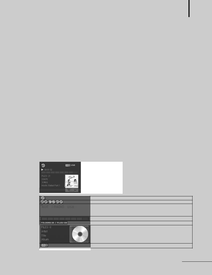
12. LCD OPERATION DISPLAY
Displays the output level meter, each bar is marked in intervals of 3 to 5dB. 1) USB Play mode
Play Mode Icon.
Single, single repeat, folder, folder repeat, play all, repeat all.
Input source display - MP3 Player, Internet Radio, AOE Stream Receiver.
Output level meter display.
Displays number of Folder and File.
Displays the information of song.
Displays USB connection status.
PMU-60N/120N/240N 5
MIXING AMPLIFIER
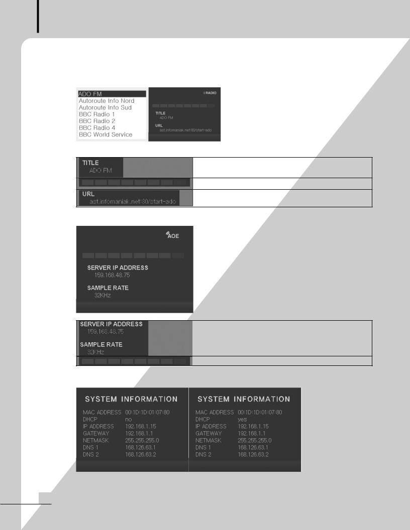
2)INTERNET RADIO
<radio list & radio main >
Displays Broadcasting station.
Output level meter display.
Displays the URL of broadcasting station.
3) AOE stream
Displays server IP address which is connected with AOE-212N. The setting of access server can be reconfigured through the internal Web browser page.
Output level meter display.
4) System Information Screen
6 PMU-60N/120N/240N
MIXING AMPLIFIER
MAC ADDRESS |
Displays default MAC ADDRESS of equipment. |
DHCP |
Displays DHCP setting. |
IP ADDRESS |
Displays IP address. |
GATEWAY |
Displays GATEWAY address. |
NETMASK |
Displays NETMASK address. |
DNS1,2 |
Displays DNS address. |
|
|
5) MENU MODE
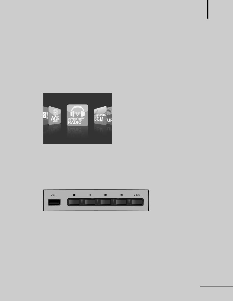
-Select the desired menu by pressing the select button (From the left, USB/AOE/Internet Radio/NetworkBGM/Set up menu).
13.USB PLAYBACK BUTTONS
1)USB input port
Insert a USB memory stick into the USB port.
Warning : only supports drives formatted in FAT or FAT32 format.
It may cause a problem ejecting a memory stick while music file in USB is playing.
2)Stop button
3)/ playback / pause button
4) , previous / next button
Moves to previous or next song by pressing the button and moves to previous or next folder by pressing the button for more than 2 second.
PMU-60N/120N/240N 7
 Loading...