


 Operation Manual
8X8 Audio Matrix System
PX/RM/LM-8000
8X8 AUDIO MATRIX SYSTEM
Welcomel
A personal welcome to you from the management and employees of Inter-M
All of the co-workers here at Inter-M are dedicated to providing excellent products with inherently good value, and we are delighted you have purchased one of our products.
We sincerely trust this product will provide years of satisfactory service, but if anything is not to your complete satisfaction, we will endeavor to make things right.
Welcome to Inter-M, and thank you for becoming part of our worldwide extended family!
CAUTION
RISK OF ELECTRIC SHOCK
DO NOT OPEN
CAUTION: TO REDUCE THE RISK OF ELECTRIC SHOCK.
DO NOT REMOVE COVER (OR BACK).
NO USER-SERVICEABLE PARTS INSIDE.
REFER SERVICING TO QUALIFIED SERVICE PERSONNEL.
WARNING
To prevent fire or shock hazard, do not expose the unit to rain or moisture.
This symbol is intended to alert the user to the presence of uninsulated “dangerous voltage” within the product’s enclosure that may be of sufficient magnitude to constitute a risk of electric shock to persons.
This symbol is intended to alert the user to the presence of important operation and maintenance (servicing) instructions in the literature accompanying the appliance.
Caution: To prevent electric shock do not use this (polarized) plug with an extension cord, receptacle or other outlet unless the blades can be fully inserted to prevent blade exposure.
Attentions: Pour prévenir les chocs électriques ne pas utiliser cette fiche polarisée avec un prolongateur, une prise de courant on une autre sortie de courant, sauf si les lames peuvent étre insérées à fond sans en laisser aucune partie à découvert.
*Do not install this equipment in a confined space such as a book case or similar unit.
*The apparatus shall not be exposed to dripping or splashing and no objects filled with liquids, such vases, shall be placed on the apparatus. *Worded: “WARNING FOR YOUR PROTECTION PLEASE READ THE FOLLOWING-WATER AND MOISTURE: Unit should not be used near water(e.g. near a bathtub, washbowl, kitchen sink, laundry tub, in a wet basement, or near a swimming pool, etc). Care should be taken so than objects do not fall and liquids are not spilled into the enclosure through openings.”
Service Instructions
*Worded: "Caution: These servicing instructions are for use by qualified service personnel only. To reduce the risk of electric shock, do not perform any servicing other than that contained in the operating instructions unless you are qualified to do so."
*Location: Instruction Manual.
NOTE : This equipment has been tested and found to comply with the limits for a Class A digital device, pursuant to Part 15 of the FCC Rules. These limits are designed to provide reasonable protection against harmful interference when the equipment is operated in a commercial environment. This equipment generates, uses, and can radiate radio frequency energy and, if not installed and used in accordance with the instruction manual, may cause harmful interference to radio communications. Operation of this equipment in a residential area is likely to cause harmful interference in which case the user will be required to correct the interference at his own expense.
* It can be heated up if you use this product in closed box or ill-ventilated place.

8X8 AUDIO MATRIX SYSTEM
Contents |
|
Unpacking ....................................................................................................................................... |
2 |
Installation |
|
Environment.................................................................................................................................... |
3 |
Important Safety Instructions............................................................................................................. |
3 |
Description....................................................................................................................................... |
4 |
Features............................................................................................................................................ |
4 |
Accessories..................................................................................................................................... |
4 |
Panel |
|
PX-8000 Front Panel........................................................................................................................ |
5 |
PX-8000 Rear Panel ........................................................................................................................ |
7 |
RM-8000 Front Panel ...................................................................................................................... |
9 |
RM-8000 Rear Panel ..................................................................................................................... |
10 |
LM-8000 Front Panel ..................................................................................................................... |
11 |
LM-8000 Rear Panel...................................................................................................................... |
12 |
Operation ...................................................................................................................................... |
13 |
Connections ................................................................................................................................... |
19 |
Block Diagram .............................................................................................................................. |
20 |
Specifications ................................................................................................................................ |
21 |
Service |
|
Procedures.................................................................................................................................... |
22 |
Schematic ..................................................................................................................................... |
22 |
Parts List ....................................................................................................................................... |
22 |
Variations and Options ............................................................................................................... |
22 |
Warranty ....................................................................................................................................... |
22 |
PX-8000/RM-8000/LM-8000 1

8X8 AUDIO MATRIX SYSTEM
Unpackingi
Please take a few minutes to read this manual to familiarize yourself with important information regarding installation, product features, and operation.
As with most electronic devices, ORIGINAL PACKAGING (OR EQUAL) IS REQUIRED in the unlikely event that the product needs to be returned for servicing.
Shortt Form InstructionsI t ti
1.Do not connect the unit to the AC mains until some preliminary settings are completed. AC mains should only be switched on later in this procedure. Ensure that the AC mains power and phantom power switches are in the OFF position.
2.Set all the output volume lever down to the minimum.
3.Connect each zone OUTPUT of the PX-8000 to the corresponding zone of an amplified loudspeaker system.
4.Connect the LOCAL AUDIO SOURCES (tape deck, CD player, tuner, etc..) to the BGM inputs on the PX-8000 and turn the input gain control knobs (on the rear panel) to half way.
5.Connect the AC mains power cord to the PX-8000 and switch the AC mains power to the ON position. Switch ON the PHANTOM POWER if condenser microphones will be used with this system.
6.Press the BGM select button located on the front panel until the illuminated number displays the desired input channel number for the local audio source.
7.Slowly side the output volume lever up on the front panel to increase the volume being sent to the amplifier for the loudspeaker system until the desired level is reached. Obviously, if there is distortion, feedback, or other cause for concern, reduce the signal level of the input or the output.
8.Connect one or more LM-8000 to each of the ZONE connectors as needed. There is no need to set the address. Connect a remote audio source or remote microphone to the LM-8000. Use the gain and BGM select button on the unit instead of the ones located on the PX-8000. The LM-8000 has a higher priority than the PX-8000 and will override the gain and BGM Selection of the PX-8000.
9.Connect one or more (maximum 4) RM-8000 units to the remote mic input connector on the back of the PX-8000. Connect a microphone to each RM-8000. Select one or more zones using the selectors on the front of the RM-8000. Speak into the microphone and adjust the signal level.
10.Set the levels for each zone as desired by using the zone gain control on the PX-8000 or by using the gain control on the LM-8000, if so equipped.
2 PX-8000/RM-8000/LM-8000

8X8 AUDIO MATRIX SYSTEM
InstallationI t ll ti
Environment
Never place this product in an environment which could alter its performance or reduce its service life. Such environments usually include high levels of heat, dust, moisture, and vibration.
Important Safety Instructions
1.Read these instructions.
2.Keep these instructions.
3.Heed all warnings.
4.Follow all instructions.
5.Do not use this apparatus near water.
6.Clean only with dry cloth.
7.Do not block any ventilation openings. Install in accordance with the manufacturer’s instructions.
8.Do not install near any heat sources such as radiators, heat registers, stoves, or other apparatus (including amplifiers) that produce heat.
9.Do not defeat the safety purpose of the polarized or grounding-type plug. A polarized plug has two blades with one wider than the other. A grounding type plug has two blades and a third grounding prong. The wide blade or the third prong are provided for your safety. If the provided plug does not fit into your outlet, consult an electrician for replacement of the obsolete outlet.
10.Protect the power cord from being walked on or pinched particularly at plugs, convenience receptacles, and the point where they exit from the apparatus.
11.Only use attachments/accessories specified by the manufacturer.
12.Use only with the cart, stand, tripod, bracket, or table specified by the manufacturer, or sold with the apparatus. When a cart is used, use caution when moving the cart/apparatus combination to avoid injury from tip-over.
13.Unplug this apparatus during lightning storms or when unused for long periods of time.
14.Refer all servicing to qualified service personnel. Servicing is required when the
apparatus has been damaged in any way, such as power-supply cord or plug is damaged, liquid has been spilled or objects have fallen into the apparatus, the apparatus has been exposed to rain or moisture, does not operate normally, or has
been dropped. S3125A
S3125A
-AVOID EXCESSIVE HEAT, HUMIDITY, DUST AND VIBRATION
Keep the unit away from locations where it is likely to be exposed to high temperatures or humidity-such as near radiators, stoves, etc. Also avoid locations which are subject to excessive dust accumulation, or to vibration that could cause mechanical damage.
-AVOID PHYSICAL SHOCKS
Strong physical shocks to the unit may cause damage. Handle the unit with care.
-DO NOT OPEN THE CASE OR ATTEMPT REPAIRS OR MODIFICATIONS YOURSELF
This product contains no user-serviceable parts. Refer all maintenance to qualified Inter-M service personnel. Opening the case and/or tampering with internal circuitry voids the warranty.
-ALWAYS POWER OFF BEFORE MAKING CONNECTIONS
Always turn the AC mains OFF before connecting or disconnecting cables. This is important to prevent damage to the unit itself as well as other connected equipment.
-HANDLE CABLES CAREFULLY
Always plug and unplug cables (including the AC mains power cord) by gripping the connector, not the cord.
-CLEAN WITH A SOFT DRY CLOTH
Never use solvents such as benzine or paint thinner to clean the unit. Wipe clean with a soft, dry cloth.
PX-8000/RM-8000/LM-8000 3

8X8 AUDIO MATRIX SYSTEM
Descriptioni ti
The PX-8000 and related components provides the latest technology combined with ease of operation to create a system which offers enormous capability and flexibility. Local audio sources may be sent to any combination of up to eight remote zones and do so with either local or remote control.
This type of flexibility makes this product ideal for any type of multi-zone system including hotels, airports, casinos, hospitals, conference centers, and restaurants.
A wide assortment of remote devices insures that the right amount of control is located in the correct locations throughout a facility.
Featurest
-New concept of audio matrix system for public addressing and emergency broadcasting
-Various audio inputs (BGM, Remote MIC, Local Wall Mount MIC & BGM, Paging MIC)
-Individual BGM broadcasting and area selection broadcasting to 8 output areas
-Unlimited expansion of output area in link with Main System (PX-8000)
-Convenient priority broadcasting (Paging MIC > DRP > RM-8000 > LM-8000 > BGM)
-Previous hearing of BGM using a monitor speaker
-Convenient installation and construction without need of ID setting (RM-8000, LM-8000)
-Voice recording by using Record & Playback IC and automatic play in link with fire contact
-Lump change of BGM for all outputs (available in link system)
-Adoption of RS-422 communication method to support a long distance
-Selection of various Chime broadcastings for MIC broadcasting (PRE/POST)
-Capable of adjusting individual tone(bass/treble) in every output area
-Convenient connection with 8CH Power Amp through adoption of lump output terminal
-Adoption of I/O signal level display
Accessories
3 Pin Terminal Block 8pcs
9 Pin Terminal Block 1 pcs Operation Manual 1pcs.
Rack Mount Screw & Washer 4pcs Foot & Screw 4pcs
4 PX-8000/RM-8000/LM-8000

8X8 AUDIO MATRIX SYSTEM
PX-8000 Frontt Panell |
|
|
|
|
|
|
|
|
||
1 |
2 |
3 |
4 |
5 |
6 |
7 |
8 |
9 |
10 |
11 |
12 13 |
14 |
15 |
|
|
16 |
17 |
|
18 |
|
|
1. MONITOR SPEAKER
Built-in 1-Watt Power Amplifier and 8Ω Monitor Speaker to monitor input channel selected out of 8 BGM sources.
2. BGM INPUT SELECTION BUTTON
Button to select one out of 8 BGM sources.
3. BGM INPUT DISPLAY
Displays selected BGM source.
4. VOLUME TO ADJUST BGM OUTPUT LEVEL FADER
A volume to adjust Main BGM broadcast to the relevant output and the output sound volume of LM-8000. The output volume of a Paging MIC and a remote MIC volume are not adjusted by this volume.
5. TALK BUTTON
You can start broadcasting if selecting the desired area and pressing the TALK button when performing Paging MIC broadcasting. In this case, character "P" is displayed on the BGM input channel display window equivalent to the selected area. This is a toggle switch and thus you can terminate broadcasting if pressing it, and the selected zone is released.
6. ESC BUTTON
Used when changing all BGM or cancel recording of the built-in recording.
7. BGM ALL / ENTER BUTTON
Used for broadcasting same BGM to all the output area. If pressing the BGM ALL button, "ALL 1" is displayed and BGM numbers increase whenever pressing it again. If a BGM to change is determined, select BGM by pressing the ENTER button.
BGM broadcasting to the output area is also changed simultaneously that the BGM number is changed when pressing the ENTER button. Press the ESC button to change all BGM or return the original status. (Applied even to system link)
PX-8000 5

8X8 AUDIO MATRIX SYSTEM
8. PAGING ALL BUTTON
If broadcasting a Paging MIC to all output areas, firstly pressing this button before pressing the TALK button enables to select all the output areas. Buttons of all the Paging broadcasting areas turn on. If pressing the buttons again, the relevant function is released. (Applied even to system link)
9. REC BUTTON
Enters into the Recording Standby Mode if pressing the REC button. Check that alphabet
character called as "-record-" is displayed. (Recording mode is released if pressing the ESC button in the Recording Standby Mode. Press the REC button to release during recording.)
If recording standby is completed, start recording by pressing this button lengthily (about a second). Check that recording is being done while the first character and ending character "-" from the "-RECORD-" rotate. If recording is completed, end by pressing the REC button. (Maximum recording time is 30sec.)
10. TREBLE/BASS/LEVEL ADJUSTMENT VOLUME
Adjusts volume and tone when broadcasting MIC and when recording built-in DRP IC.
11. BGM INPUT LED
A LED of the input channel, where BGM signal comes from, turns on.
12. POWER SWITCH
A switch to apply power supply to the system
13. MONITOR SPEAKER VOLUME
A volume to adjust BGM volume output to the Monitor Speaker
14. MASTER/SLAVE LED
Displays mode in link of PX-8000. This turns on depending on the status of the rear Link Mode switch.
15. WALL MOUNT CONTROLLER (LM-8000) ENABLE BUTTON
This is a toggle switch to select whether the WALL Controller (LM-8000) connected to each output zone is enable/disable. If the button turns on, selection of BGM and adjustment of BGM output volume are done only by LM-8000. If the button turns off, the related right is transferred to PX-8000. In this case, volume of the output area is returned to the original status. Even for PX-8000 powering ON/OFF, the right is automatically memorized.
16. PAGING ZONE SELECTION BUTTON
Button to select the desired output area when broadcasting using a paging MIC. Has a toggle function and the selected button turns on.
17. PAGING MIC
An input jack to connect a Paging MIC. It is recommended to use a balanced MIC.
18. BGM LIST
A position to write name for user to easily discern each BGM input source.
6 PX-8000
8X8 AUDIO MATRIX SYSTEM
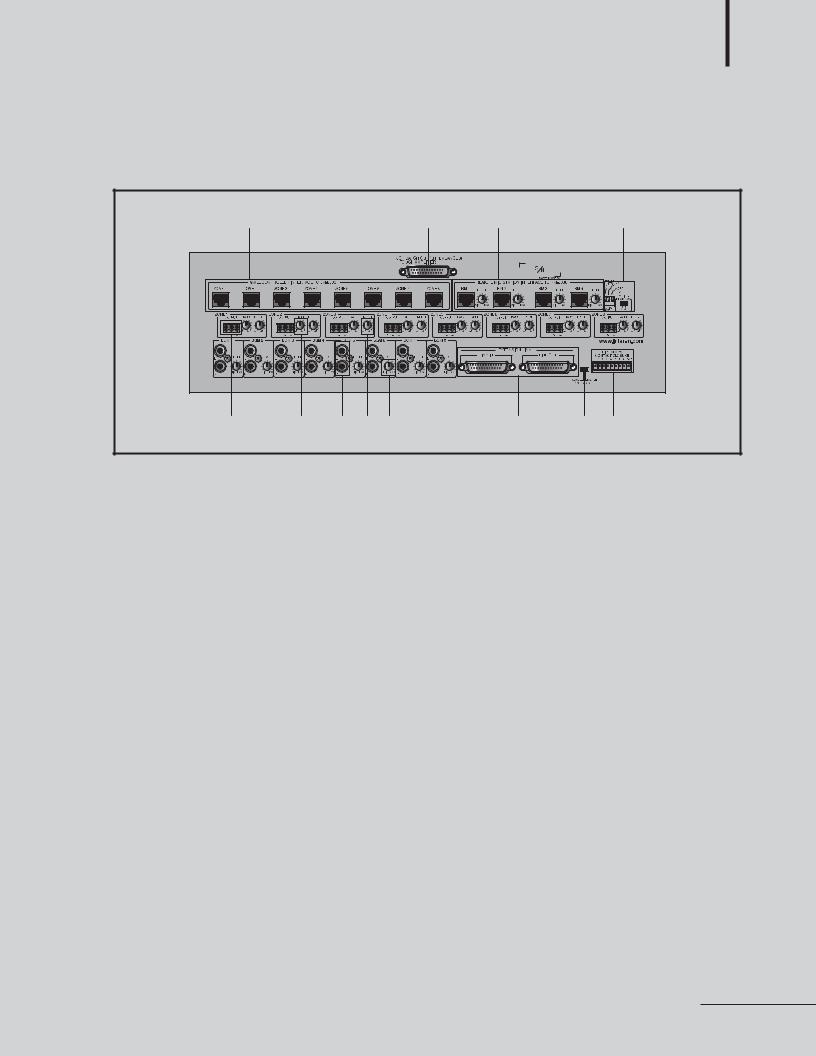
PX-8000 Rear Panell
|
1 |
|
|
|
2 |
3 |
|
4 |
5 |
6 |
7 |
8 |
9 |
|
10 |
11 |
12 |
1. LM-8000 CONNECTION TERMINAL
A LM-8000 can be connected every output zone.
PIN Number |
1 |
2 |
3 |
4 |
5 |
6 |
7 |
8 |
Functions |
RX- |
RX+ |
TX- |
TX+ |
GND |
VCC |
AUDIO+ |
AUDIO- |
|
|
|
|
|
|
|
|
|
Color |
BLU |
BLU/WHT |
GRN |
GRN/WHT |
ORG |
ORG/WHT |
BRN |
BRN/WHT |
|
|
|
|
|
|
|
|
|
Ex) RXof PX-8000 is connected to TXof LM(RM)-8000 and RX+ of PX-8000 is connected to TX+ of LM(RM)-8000.
2. 8-CH LUMP OUTPUT TERMINAL
A lump output terminal of 8-CH. Same function as individual output terminal of zone.
3. RM-8000 CONNECTION TERMINAL AND VOLUME
4 units of RM-8000 can be connected.And to adjust input sound by RM-8000.
Its priority is order of RM1 > RM2 > RM3 > RM4. Connection method is same as LM-8000.
4. PAGING MIC CHIME MODE SWITCH AND PHANTOM POWER SWITCH
The Paging MIC is built-in a Phantom Power (DC +24V) in order to support a condenser MIC as well as general dynamic MIC and is a switch to turn ON/OFF. You can use a dynamic MIC for Off and use a condenser MIC for On.
Set the mode so that Chime broadcasting is automatically done before or after broadcasting using a DIP Switch. (Chime increased by 2 tones is broadcast if the upper 2 tones and the upper 4 tones are set to On. Chime function operates when pressing the TALK button of the paging broadcasting.)
A.SWITCH1 ON : Chime increased by 2 tones for starting is broadcast when pressing the TALK button.
B.SWITCH2 ON : Chime increased by 4 tones for starting is broadcast when pressing the TALK button.
C.SWITCH3 ON : Chime decreased by 4 tones for ending is broadcast when pressing the TALK button.
D.SWITCH1, 2 ON : Same as for SWITCH1 ON.
PX-8000 7
 Loading...