


ARM-911

Inter-M, Ltd. (Korea) began operations in 1983.
Since then, Inter-M has grown to become one of the largest manufacturers
of professional audio and commercial sound electronics equipment in the world.
Inter-M has gained worldwide recognition for its own branded products,
as well as private label manufacturing of electronics sold under other names (OEM).
The company is no longer just a Korean company, but rather a global company
that is truly international in scope, with factories and offices in Korea and China,
and sales and marketing operations located in Japan, Europe, and the U.S.A.
With more than 850 employees around the globe,
Inter-M is well-poised for further growth and expansion.
Inter-M Americas, INC.
13875 ARTESIA BLVD. CERRITOS, CA 90703 USA
TEL : +1-562-921-0313, FAX : +1-562-921-0370
Home Page : http://www.inter-m.net, E-mail : info@inter-m.net
Inter-M Corporation
SEOUL OFFICE:653-5 BANGHAK-DONG, DOBONG-GU, SEOUL, KOREA
TEL : +82-2-2289-8140~8, FAX : +82-2-2289-8149
Home Page : http://www.inter-m.com, E-mail : overseas@inter-m.com
MADE IN KOREA
September 2013 133

Operation Manual
Automated Remote Message
ARM-911
AUTOMATED REMOTE MESSAGE
Welcome
Welcome
A personal welcome to you from the management and employees of Inter-M
All of the co-workers here at Inter-M are dedicated to providing excellent products with inherently good value,
and we are delighted you have purchased one of our products.
We sincerely trust this product will provide years of satisfactory service, but if anything is not to your complete
satisfaction, we will endeavor to make things right.
Welcome to Inter-M, and thank you for becoming part of our worldwide extended family!
This s ym bol is intende d to a lert the user to t he
CAutION
RISK OF ELECTRIC SHOCK
DO NOT OPEN
CAUTION: TO REDUCE THE RISK OF ELECTRIC SHOCK.
DO NOT REMOVE COVER (OR BACK).
NO USER-SERVICEABLE PARTS INSIDE.
REFER SERVICING TO QUALIFIED SERVICE PERSONNEL.
Caution: To prevent electric shock do not use this (polarized) plug with
Attentions: Pour prévenir les chocs électriques ne pas utiliser cette
WARNING
To prevent fire or shock hazard, do not
expose the unit to rain or moisture.
*WARNING FOR YOUR PROTECTION PLEASE READ THE FOLLOWING-WATER AND MOISTURE: Unit should not be used near water(e.g.
near a bathtub, washbowl, kitchen sink, laundry tub, in a wet basement, or near a swimming pool, etc). Care should be taken so than objects do
not fall and liquids are not spilled into the enclosure through openings.
*Do not install this equipment in a confined space such as a book case or similar unit.
*This apparatus shall not be exposed to dripping or splashing and no objects filled with liquids, such vases, shall be placed on the apparatus.
*This apparatus shall be connected to a mains socket outlet with a protective earthing connection.
It has heed to be easy to disconnect the device. To disconnect the device from power, separate AC input cable from inlet or unplug the AC Cord.
*
CAutION
*These servicing instructions are for use by qualified service personnel only. To reduce the risk of electric shock, do not perform any servicing
other than that contained in the operating instructions unless you are qualified to do so.
NOtE
*This equipment has been tested and found to comply with the limits for a Class A digital device, pursuant to Part 15 of the FCC Rules. These limits are
designed to provide reasonable protection against harmful interference when the equipment is operated in a commercial environment. This equipment
generates, uses, and can radiate radio frequency energy and, if not installed and used in accordance with the instruction manual, may cause harmful
interference to radio communications. Operation of this equipment in a residential area is likely to cause harmful interference in which case the user will
be required to correct the interference at his own expense.
presence of uninsulated “dangerous voltage” within
the prod uct’ s enclo sure that may be of su fficien t
magnitude to constitute a risk of electric shock to
persons.
This s ym bol is intende d to a lert the user to t he
presence of important operation and maintenance
(servicing) instructions in the literature accompanying
the appliance.
an extension cord, receptacle or other outlet unless the blades
can be fully inserted to prevent blade exposure.
fiche polarisée avec un prolongateur, une prise de courant
on une autre sortie de courant, sauf si les lames peuvent
étre ins ér ées à fo nd sans e n laisser auc un e pa rtie à
découvert.

AUTOMATED REMOTE MESSAGE
Contents
Contents
Unpacking .......................................................................................................................................2
Installation
Environment....................................................................................................................................2
Important Safety Instructions.............................................................................................................2
Features............................................................................................................................................3
Front Panel ......................................................................................................................................4
Rear Panel .......................................................................................................................................5
Operation Method
1. SD Disk Function .........................................................................................................................7
2. SD Disk Copy Function ................................................................................................................7
3. Telephone Paging........................................................................................................................8
Web-browser Interface Configuration
1. Accessing to the ARM-911 Web-browser......................................................................................9
2. Network Setting ..........................................................................................................................9
3. Time Signal Setting....................................................................................................................10
4. Priority Setting...........................................................................................................................14
5. AUX Input Setting......................................................................................................................15
6. Level Setting..............................................................................................................................15
7. EQ Setting ................................................................................................................................16
8. RM Setting................................................................................................................................17
9. Message Control .......................................................................................................................18
10. Contact Setting........................................................................................................................19
11. Time Setting............................................................................................................................20
12. Log View ................................................................................................................................21
13. Upgrade.................................................................................................................................22
14. Restart....................................................................................................................................23
15. Factory Setting ........................................................................................................................23
16. Password Setting .....................................................................................................................24
Applications ..................................................................................................................................25
Block Diagram ..............................................................................................................................26
Specifications ................................................................................................................................27
Dimensions ...................................................................................................................................28
Service
Procedures....................................................................................................................................29
Schematic.....................................................................................................................................29
Parts List .......................................................................................................................................29
Variations and Options ...............................................................................................................29
Warranty .......................................................................................................................................29
ARM-911
1

AUTOMATED REMOTE MESSAGE
S
3125A
Unpacking
Unpacking
Although your ARM-911 is neither complicated nor difficult to operate, we recommend you take a few minutes
to read this brief manual and familiarize yourself with the important information regarding product features,
setup and operation.
As with most electronic devices, we strongly recommend you retain the original packaging. In the unlikely event
the product must be returned for servicing, the original packaging (or reasonable equivalent) is required.
Installation
Installation
Environment
Never place this product in an environment which could alter its performance or reduce its service life. Such
environments usually include high levels of heat, dust, moisture, and vibration.
IMPORTANT SAFETY INSTRUCTIONS
1. Read these instructions.
2. Keep these instructions.
3. Heed all warnings.
4. Follow all instructions.
5. Do not use this apparatus near water.
6. Clean only with dry cloth.
7. Do not block any ventilation openings. Install in accordance with the manufacturer’s instructions.
8. Do not install near any heat sources such as radiators, heat registers, stoves, or other apparatus (including
amplifiers) that produce heat.
9. Do not defeat the safety purpose of the polarized or grounding-type plug. A polarized plug has two blades
with one wider than the other. A grounding type plug has two blades and a third grounding prong. The wide
blade or the third prong are provided for your safety. If the provided plug does not fit into your outlet, consult
an electrician for replacement of the obsolete outlet.
10. Protect the power cord from being walked on or pinched particularly at plugs, convenience receptacles, and
the point where they exit from the apparatus.
11. Only use attachments/accessories specified by the manufacturer.
12. Use only with the cart, stand, tripod, bracket, or table specified by the manufacturer, or sold with the apparatus.
When a cart is used, use caution when moving the cart/apparatus combination to avoid injury from tip-over.
13. Unplug this apparatus during lightning storms or when unused for long periods of time.
14. Refer all servicing to qualified service personnel. Servicing is required when the
apparatus has been damaged in any way, such as power-supply cord or plug is
damaged, liquid has been spilled or objects have fallen into the apparatus, the
apparatus has been exposed to rain or moisture, does not operate normally, or has
been dropped.
S3125A
2
ARM-911

AUTOMATED REMOTE MESSAGE
Features
Features
- Direct broadcasting of Emergency Message
By pressing one of 10 instant play buttons, message file can be directly played.
- SD Card Backup
Backup SD card is installed inside so that Front SD card can be copied to the backup SD card.
- MP3 Decoding
MP3 file format is supported.
- Remote Control by Network
Using Network, ARM-911 can be controlled at remote place.
- Remote Control by RS-232C
Using RS-232C, ARM-911 can be controlled at remote place.
- Remote Control by Tel In (DTMF)
Using telephone, 10 front buttons can be controlled and voice can be broadcasted.
- Scheduling by Network
Using Network, scheduled broadcasting can be done.
- Variable Input sensitivity of AUX Input
Using GUI (Graphic User Interface), the Input sensitivity can be selected -50dBu, -10dBu or +4dBu.
- Contact Input
Using 10 Contact Inputs, 10 front buttons can be controlled.
- Contact Output
Contat Output can be set using GUI, then the contact is output when the message is played.
- Fault Output
NO, NC fault dry contact is provided.
ARM-911
3
AUTOMATED REMOTE MESSAGE
12 56
34
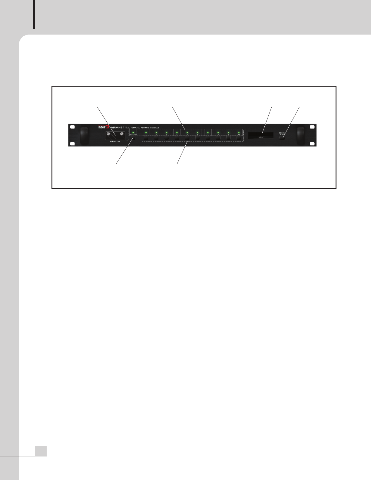
Front Panel
Front Panel
1. SD CARD COVER
2GB SD Card is installed.
Be sure the direction when insert a SD card into the slot.
Only 2GB memory can be used.
2. INDICATING LED
The LED is lit when the button is pressed.
3. COPY BUTTON
Use this button to copy the front SD card to the backup SD card which is inside the unit.
The backup SD card is 2GB. When press the COPY button, the window displays ‘PRESS THE MODE KEY
ONCE MORE’. Press the Display mode button to start COPY. If the Display mode button is not pressed within
about 3 seconds, then the COPY function is cancelled.
During copy the SD card, no other functions can be used.
NOTE: Do not turn off the power during copying the memory disc.
4. INSTANT PLAY BUTTONS
Use this button to play the file in the SD card directly.
5. DISPLAY WINDOW
The display shows the current status of the unit.
6. DISPLAY MODE BUTTON
Use this button to change the display mode.
4
ARM-911
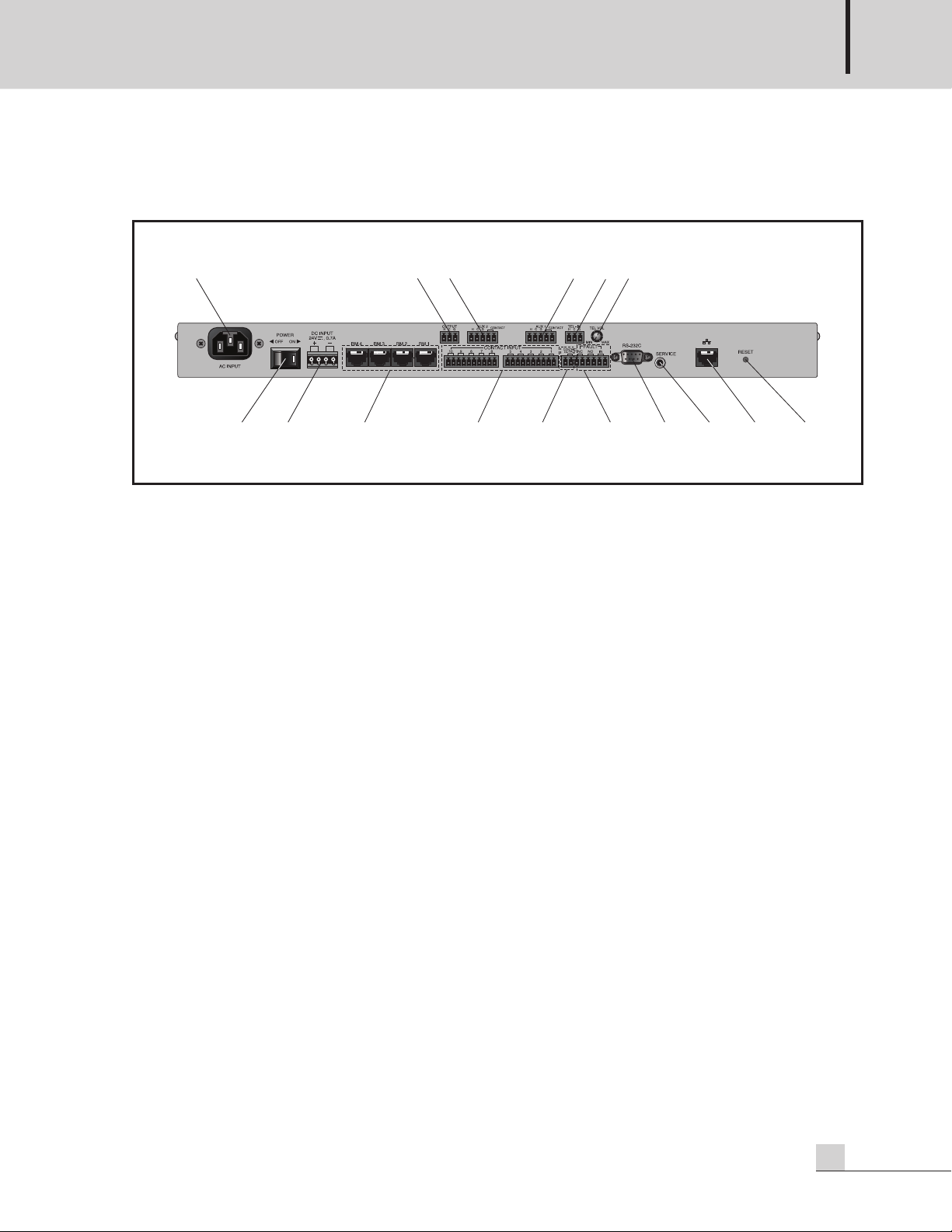
Rear Panel
1
23 4 5
7 13 14 15 16
1
2 11 10
8
9
6
Rear Panel
AUTOMATED REMOTE MESSAGE
1. AC INLET
Connect the power cable which is supplied with the unit.
2. POWER SW
Use this switch to turn the power on or off.
.
3. DC INPUT
Connect a DC24V power source to this terminal.
Make sure the polarity when make a connection.
4. RM INPUT TERMINAL
Connect the RM-911D or RM-911W to this terminal.
Be sure for the CAT5E cable not to exceed the maximum operable distance.
*Maximum length of CAT5E cable between ARM-911 and RM-911.
Cable resistance ≤ 30Ω: 300m
30Ω < cable resistance ≤ 80Ω: 100m
5. CONTACT INPUT
To play the file directly which is in the SD card, make a short of the each input contact.
6. CONTACT OUTPUT
If the contact output is set using GUI, then the contact is output when the message is played.
7. FAULT INPUT / OUTPUT
If the Fault input pins are opened, then the window displays ‘FAULT-IN’.
If the Fault input pins are shorted, then it is nornmal state.
NC means Normally Closed, when it is in fault status it is opened.
NO means Normally Opened, when it is in fault status it is closed.
ARM-911
5
AUTOMATED REMOTE MESSAGE
8. TEL IN
onnect to a telephone exchange system for paging purposes.
C
If a DTMF signal is inputted, then the unit decode the DTMF tone and play the corresponded file which is in
the SD card.
9. TEL VOLUME
Turn the volume clockwise to increase the volume.
Turn the volume counter-clockwise to decrease the volume.
10. AUX1 INPUT
Connect AUX signal source to this terminal. The input sensitivity can be set using GUI (Graphic User
Interface), -50dBu, -10dBu or +4dBu. When use a microphone, the phantom power can be set using GUI.
The phantom power is 12V.
This input is activated by sensing the signal level so that the input is on or off by the input Signal level. When
the input contact is closed, the input is activated so that the input can be controlled by the input contact.
NOTE: DO NOT turn on the phantom power when the input is not used for the phantom microphone.
11. AUX2 INPUT
Connect AUX signal source to this terminal. The input sensitivity can be set using GUI (Graphic User
Interface), -50dBu, -10dBu or +4dBu. When use a microphone, the phantom power can be set using GUI.
The phantom power is 12V.
This input is activated by sensing the signal level so that the input is on or off by the input signal level. When
the input contact is closed, the input is activated so that the input can be controlled by the input contact.
NOTE: DO NOT turn on the phantom power when the input is not used for the phantom microphone.
12. AUDIO OUTPUT
This is the audio output terminal. The output level can be controlled by GUI (Graphic User interface).
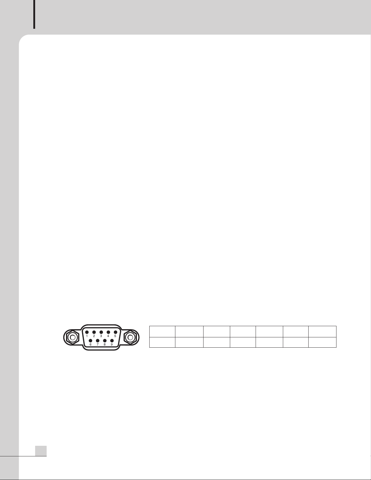
13. RS-232C TERMINAL
This terminal allows control by a remote controller such as AMX / CRESTRON etc. The control protocol can
be downloaded from the home page. (www.inter-m.com)
The maximum cable length should be below 15m.
Pin 123 456-9
Purpose X Receive Transmit X Ground X
14. SERVICE TERMINAL
This terminal is used for the software upgrade.
15. NETWORK TERMINAL
10/100 Base-Tx is supported.
16. RESET
Use this reset switch to make this unit to factory default setting.
6
ARM-911
Operation Method
Operation Method
1. SD Disk Function
2GB SD memory is installed both front SD card and internal Backup SD card.
(1) Take out the SD memory from the unit.
AUTOMATED REMOTE MESSAGE
Screw off the cover.
(2) Storing message files
①Save 10 message files into the SD memory.
②The track number of the SD disc is in numerical order.
The track number is directly corresponded to the front 10 buttons. So, name the message files as below.
01.mp3, 02.mp3, ......, 09.mp3 and 10.mp3.
(3) Plug the SD memory into the slot
Be sure the direction when insert a SD memory into the slot.
Follow the direction silk under the slot.
Plug the SD memory into the slot until it is locked.
Screw the cover on the slot.
(4) The window displays ‘READY’.
(5) Press the Instant Play Button from 1 to 10 respectively to check the message file stored in the SD memory.
When press the Instant Play Button, then the indicating LED is lit.
If the files stored in the SD memory is less than 10 files, then the correspond indicating LED is not lit even if
the button is pressed.
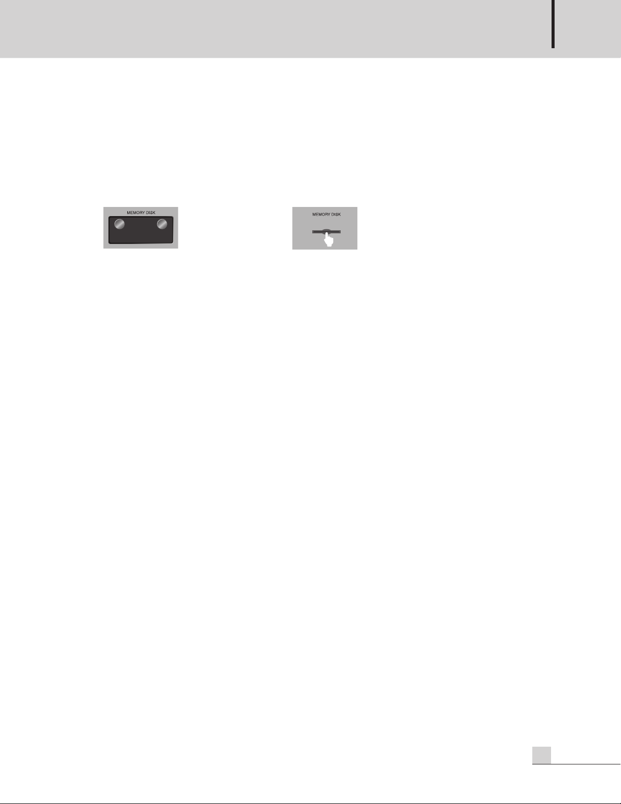
Push and r elease th e center o f the SD
memory and then take out the SD memory.
The window displays ‘No Device’.
(6) Press the button again to stop playback.
2. SD Disk Copy Function
Use this function to make a backup for the SD memory.
(1) Press the COPY button on the front. The window displays ‘PRESS THE MODE KEY ONCE MORE’. Press the
DISPLAY MODE to start copy. If the Display Mode button is not pressed within about 3 seconds, then the
COPY function is cancelled.
The unit reads the files from the front SD memory and then copy to the Internal backup SD memory.
The window displays ‘COPYING’.
When the copy is finished, the window displays ‘READY’.
(2) Take out the SD memory from the front slot.
(3) Press the Instant Play Button from 1 to 10 respectively to check the message files copied from the front SD
memory.
ARM-911
7
 Loading...