

Page 1
DVR Installation Manual
1/2/2014
V1.1
truVision 11c Series DVR’s
Page 2

Table of Contents
INTRODUCTION ................................................................................................................................................................ 3
WORKFLOW ...................................................................................................................................................................... 4
INSTALLATION WORKSHEET ...................................................................................................................................... 5
DEFAULT DVR LOGIN ..................................................................................................................................................... 6
FIRMWARE VERSION ...................................................................................................................................................... 7
NETWORK AND TIME SETUP ....................................................................................................................................... 8
ROUTER SETTINGS ........................................................................................................................................................ 10
SMTP SETTINGS ............................................................................................................................................................. 11
USER SETTINGS .............................................................................................................................................................. 12
RECORDING SETUP ....................................................................................................................................................... 13
SCHEDULED RECORDING MODE ............................................................................................................................... 14
ALARM ACTIONS AND INPUT SETUP ...................................................................................................................... 15
EVENT RECORDING ....................................................................................................................................................... 16
CONFIGURE I-VIEW NOW ENTRY DELAYS ............................................................................................................. 17
TEST SETTINGS .............................................................................................................................................................. 18
TROUBLESHOOTING ..................................................................................................................................................... 19
GLOSSARY ........................................................................................................................................................................ 20
This manual will provide assistance in setting up I-View Video Verification functionality based on sensor
events configured in the interlogix truVision 11c. It is not a replacement for the excellent manuals for the
interlogix truVision 11c, which can be downloaded from their site at
http://www.interlogix.com/video/product/truvision-dvr-11/.
interlogix truVision DVR 11c © 2014 I-View Now, LLC. All Rights Reserved. Page 2
Page 3
Introduction
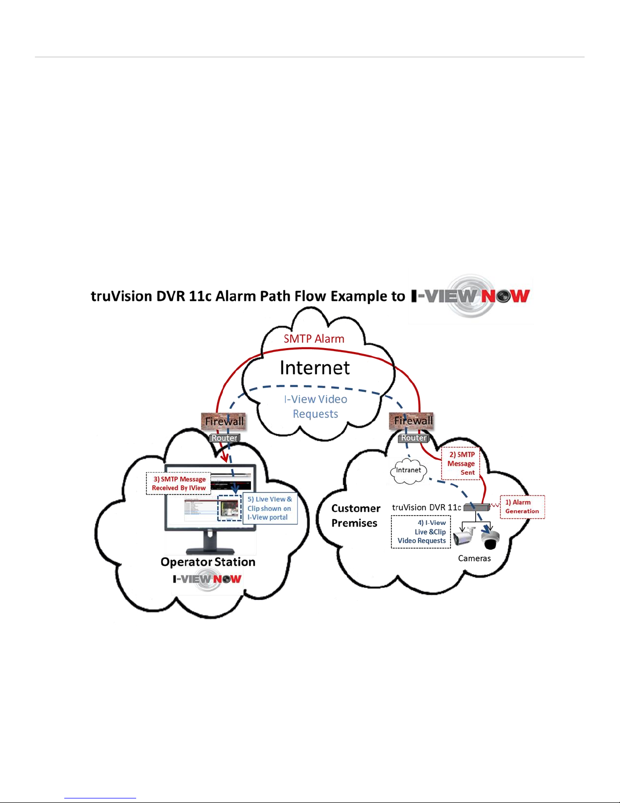
Once the DVR has been set up it is ready to be tested with I-View. The following illustration shows the path of two
message flows comprising a typical “Video Verification” scenario:
1-3 - An onsite alarm ‘event’ causes an SMTP message to be sent to the I-View Now system. The alarm event is
usually the result of a simple contact closure wired into the back panel of the DVR.
4, 5 - The resulting message path I-View initiates upon receipt of the SMTP message to retrieve the ‘pre’ and
‘post’ alarm video associated with the alarm event. The number of pre and post seconds can vary but it’s usually
not less than 3 and normally about 10 on either side of the alarm condition that initiates the sequence.
The user can view one or more consecutive alarm event ‘clips’ as they arrive from the I-View Now portal via a cell phone,
or a PC or tablet device’s browser. With each clip is the ability to see one or more “Live Views” for various cameras
associated with the DVR that generated the SMTP alarm.
interlogix truVision DVR 11c © 2014 I-View Now, LLC. All Rights Reserved. Page 3
Figure 1
Page 4

Workflow
The following steps describe a high level workflow to be followed in order to properly configure and install a truVision
DVR 11c to work with I-View Now. Subsequent sections will provide more detail on each step outlined here.
1. Network Setup: Configure the DVR and router/firewall at the site so the DVR can connect to the Internet.
Router/Firewall instructions will vary by location, manufacturer and site LAN configuration. In addition, data
from this step needs to be input into the i-viewnow.com portal, such as the External IP Address for the site, as
well as the “Client Port”. These are necessary so that the I-View Now portal can gain access to the DVR for “Live
Views” and retrieving video “Clips” associated with alarm events. Finally, a static IP must be available for the
DVR on site which the router will send I-View requests to as well as services on specific ports.
2. Configure SMTP email: This will be used to communicate alerts and alarms to I-View Now. The SMTP server and
SMTP ID provided on the “Installer Data” Worksheet obtained from the i-viewnow.com portal is a necessary for
this step.
3. User Setup: Change the default administrator login password from ‘1234’ to a unique password. I-View Now
will be using this password to log into the device programmatically for ‘Live View’ and ‘Clip’ retrieval. As such I-
View Now recommends using the suggested password on the “Installer Data” worksheet. If a password for the
admin account on the DVR differs from the one provided on the worksheet, this needs to be communicated to IView administrators in order to update the database.
4. Alarm Input Setup: The technician will configure alarm inputs on the back of the DVR to perform two actions:
1. Trigger recording on all connected cameras
2. Send SMTP (email) alerts to I-View Now when an alarm event occurs
5. Recording Setup: The DVR can be set to record by schedule or by events. Event recording from alarm inputs is
the recommended approach for I-View Now although other modes, such as motion detection, are possible with
some caveats. These are described in more detail in this section.
6. Configure I-View Now Entry Delay: Entry delay is configured through the I-View Now portal.
7. Test: Here you will test the individual inputs on the DVR as they are connected to your alarm panel relays or
other input devices. It is recommended that you test all inputs for functionality and to ensure the proper
workflow is configured within the I-Viewnow.com portal.
8. Trouble Shooting: This section is provided to help the technician troubleshoot common problems encountered
while installing this particular type of DVR.
interlogix truVision DVR 11c © 2014 I-View Now, LLC. All Rights Reserved. Page 4
Page 5
Installation Worksheet
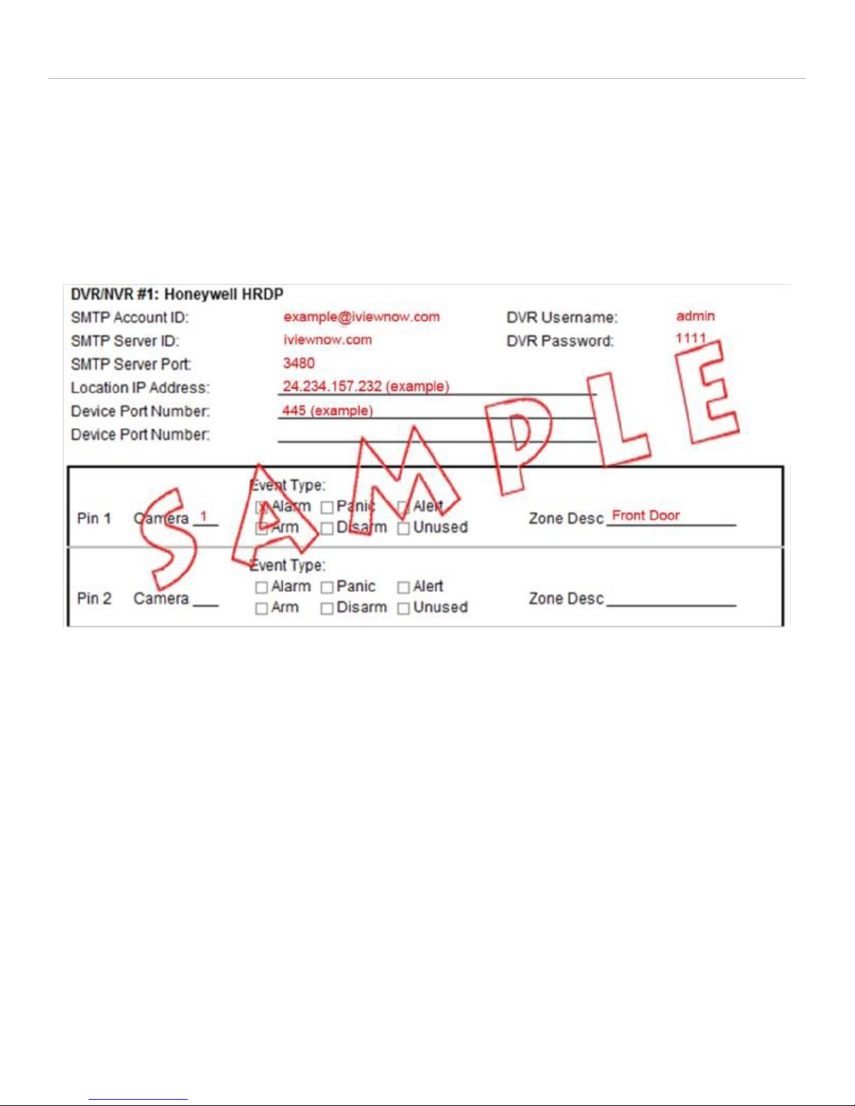
The I-View Now Portal Installation Worksheet is created after entering the DVR make and model into the system. A
portion of an example worksheet is printed below. This sheet should be generated from the system before attempting
to set up the site for integration with I-View as it enables setup of the DVR onsite login and password as well as the
means to send SMTP messages back to the I-View Now server. There is a place on the form for recording the Location IP
Address which is the external IP address used for the router at the site facing the Internet. In addition the ports on the
external router that will be forwarded to the DVR should be noted on this form. This information needs to be input into
the i-viewnow.com system so it will know the external IP address and ports used to communicate from the site through
the router at the site and onto the DVR.
Figure 2
Retrieve the IP address by asking the Customer/IT department for the IP address, or visit http://whatismyip.org while
on-site for a possible correct address; however, verify with the IT department that the IP address discovered is valid to
use as a target from the I-View servers. The IT Site Administration must enable port forwarding from their
router/firewalls to the Speco DS 16 DVR port address.
interlogix truVision DVR 11c © 2014 I-View Now, LLC. All Rights Reserved. Page 5
Page 6

Default DVR Login
USB Mouse
VGA Cable
VGA Port
Plug a monitor into the VGA output on the DVR. Also, plug the mouse provided with the DVR into the front side USB port
of the DVR unit. The mouse must be plugged in before the DVR is turned on, or the DVR will not recognize it.
User Name: admin
Password: 1234
Although a keyboard can be used it’s not required as the system will provide for mouse selection of alpha-numeric
characters.
interlogix truVision DVR 11c © 2014 I-View Now, LLC. All Rights Reserved. Page 6
Page 7

Firmware Version
The version of the firmware on the DVR tested with I-View Now is shown below. The DVR should have this version set to
ensure proper interoperation with I-View Now.
Figure 3
interlogix truVision DVR 11c © 2014 I-View Now, LLC. All Rights Reserved. Page 7
Page 8

Network and Time Setup
After logging into the device for the first time, the first setting that should be changed is the IP address. The DVR
requires a static or fixed internal IP address and one or more communication ports need to be forwarded to it from the
firewall/router on site facing the Internet.
With the Mouse, Right Click on the middle of the display
Select Menu, The Default user name is admin
Click on the Password field
Use the mouse to enter the password; the default is 1234. To change this to match the settings on the Installation
sheet, see the section on User Settings.
After entering the password, it will bring up the Main Menu
On the main menu click on the green menu that looks like a small hierarchy of squares
This should bring up a menu of network items. Setting up the network configuration is the focus of this section.
Figure 4
The Enable DHCP box should be unchecked and the IPv4, Subnet and Default Gateway addresses should be set
to values provided by to the IT team responsible for the site’s addressing configuration.
Typically the static IP address on the DVR are in the form of a private network address, e.g. 192.168.x.y, of a site
specific Intranet address, since it is proxied by a router/firewall facing the Internet.
The IPV6 values are not used.
The Preferred DNS server is typically 8.8.8.8 with an alternate of 4.2.2.2.
Be sure to apply these and any other settings made by clicking on the “Apply” button at the bottom of the
screen.
interlogix truVision DVR 11c © 2014 I-View Now, LLC. All Rights Reserved. Page 8
Page 9

Most DVRs have a time reference in order to periodically synchronize clock settings. Setting up the proper time starts by
selecting the “Time” menu item under Monitor.
Figure 5
Set the Time Zone for the location where the DVR will be located as shown
Typically, DST (Daylight Savings) is enabled so the time sent to I-View will match the local time I-View requests
when it attempts to retrieve the pre and post clip video associated with the time of an event.
In addition, if the system is connected to a public network, it can be configured to automatically synchronize its time
settings to a public network, such as the National Time Center. The DVR manual provides more detail on options for
how to do this. You can see the default settings here after selecting the Network settings icon and selecting NTP as
shown below:
Figure 6
interlogix truVision DVR 11c © 2014 I-View Now, LLC. All Rights Reserved. Page 9
Page 10

Router Settings
Router configurations for I-View are unique based on the specific router/firewall onsite. I-View Now requires at least
two ports to be forwarded to the Device. You can change the server and HTTP ports from the default settings in the
Network Settings window. This can be done either through port forwarding or NAT (Network Address Translation)
depending on what the installation site’s router supports.
With either of these router features, any unused/unfiltered external port can be forwarded to the DVR’s Server Port
(Also referred to as the Video Port). For example external port 9000 could be forwarded to the DVR on port 8000
internally. Similarly, external port 8080 could be forwarded to the DVR’s internal port 80. Using port forwarding it’s
possible to not need to change the DVR’s default internal port settings.
Another approach is to forward external ports to the DVR using the same external and internal port. In this case, the
ports must be set on the DVR through Network Settings. Common ports used for forwarding the HTTP port are 1024,
1025, 1026, 1027 or 8080. Common ports used for forwarding the command port are 8010, 8011, 9000 or 9010. For
these situations it is the External IP Address and External Port numbers that must be entered into the I-View Now
“Installer’s Portal” so that the I-View system is aware of the proper port with which to communicate to the DVR with.
As was mentioned in the workflow overview, the external IP address and client port used to forward messages to the
DVR must be input into the i-viewnow.com portal. Through this fashion I-View will know how to route requests across
the Internet as well as the port used to talk to the DVR.
The default server port for this NVR is 8000 while that of the default HTTP port is 80. In addition, this particular camera
unit makes use of RTSP (Real Time Streaming Protocol) and as such the router needs to make the RTSP ‘well-known’ port
of 554 available or an alternate port must be configured. In general any ports used must be unblocked in any firewall or
boundary security devices (which is typically just the router). To configure the RTSP service port for the DVR:
1. Click the Network Settings icon in the menu toolbar and then click More Settings.
2. Enter the RSTP port value. The default value is 554.
3. Click Apply to save the settings.
interlogix truVision DVR 11c © 2014 I-View Now, LLC. All Rights Reserved. Page 10
Figure 7
Page 11

Since the router/firewall at the entrance to the site can originate from any number of manufacturers this manual
doesn’t attempt to specify exactly how to configure each one to provide port forwarding for the above services. As
such, it’s best to discuss the specific needs of I-View port forwarding discussed above first with the IT personnel
responsible for maintaining the router at the site.
SMTP Settings
This section provides more detail on how to set up SMTP on the DVR to allow Alarm notifications to be sent to I-View
Now. SMTP is an Internet protocol that enables basic email messages to be sent using simple encoding, such as base
64, to the I-View system when an alarm event occurs.
From the Network Settings menu
Click on the E-mail button and a menu similar to that below should appear:
Figure 8
Uncheck Enable Server Authentication as it isn’t required when sending an email to the I-View Now system.
The DVR needs an SMTP Sender Address to enable it to send an email to the I-View Now system when an alarm
is detected. This e-mail address should be on the installer’s sheet as the “SMTP Account ID” which is used as
both the ‘from’ and ‘to’ e-mail address.
Enter ivnview.com in the SMTP Server Field as that is the address of the I-View Now email server.
For this DVR installation SSL is the desired method of communication and port 9116 is the preferred port to
communicate with the I-View Now email server.
From the “Installation Worksheet.” Enter the SMTP ID into the Sender and Sender’s Address
Check Enable SSL, then “Apply” and the email settings should be complete.
The “Test” button next to the “Apply” button can be checked to verify the basic email settings are complete.
Note Test does not verify that the DVR’s SMTP ID is correct, only that the DVR was able to reach I-View Now via
SMTP. The full test is when an alarm contact is closed and a message is sent to I-View with the corresponding
interaction with I-View to provide Live View and Video Clips.
interlogix truVision DVR 11c © 2014 I-View Now, LLC. All Rights Reserved. Page 11
Page 12

User Settings
This section explains how to change the DVR’s password.
The administrator account includes extended menu with full access to all settings. The Administrator has the
authority to add, delete or configure parameters for most of the system functions.
There can only be one administrator.
The user name is admin. The name cannot be modified. The default password is 1234. From the main menu
click on “Menu” and the Login screen appears.
Figure 9
After logging in, one can add users, modify permissions, etc. by first clicking on the image of a person at the top
of the screen as shown below:
Figure 10
The MAC address, permissions, adding/deleting users can all be controlled from this screen. Selecting “Change
Password” after selecting admin allows the admin password to be changed. The password on the Installation
form should be set to match the DVR’s password in order to allow I-View to programmatically log onto the DVR
when requesting clips or initiating Live View.
interlogix truVision DVR 11c © 2014 I-View Now, LLC. All Rights Reserved. Page 12
Page 13

Recording Setup
The Interlogix truVision DVR supports various recording modes which can be enabled via the user interface for the DVR.
Before you can set up the DVR to begin recording, you must configure general recording settings for the analog cameras.
The DVR manual covers the details on initializing recording settings.
When using I-View it’s important to remember that if a continuous recording mode is enabled in addition to event based
recording (event based recording is required for I-View alarm based recording) the effect may be to slow the retrieval of
clips as the I-View system will need to wait for a current block of video to finish recording before retrieving it.
interlogix truVision DVR 11c © 2014 I-View Now, LLC. All Rights Reserved. Page 13
Page 14

Scheduled Recording Mode
Scheduled recording mode can be configured to record continuously. There are some downsides to using this mode in
conjunction with I-View:
The DVR’s hard drive fills faster and older video will be overwritten as new video is generated.
Clip retrieval has to wait for the DVR to finish the current recording block to finish before I-View Now can
retrieve it.
The manual for the DVR goes into more detail on how to define and set up various recording schedules. Note, for I-View
integration it’s important that Pre-record and Post-record parameters are set to an interval that exceeds the minimum
pre and post alarm video time recording intervals that the I-View system will attempt to retrieve and show as a clip for
the user.
interlogix truVision DVR 11c © 2014 I-View Now, LLC. All Rights Reserved. Page 14
Page 15

Alarm Actions and Input Setup
When setting up the rules for alarm detection, you also specify how the event will be reported. You can select more than
one notification type but to forward the event to I-View it’s necessary to configure the DVR to “send e-mail.” Thus
ensure that the DNS address associated with the DVR has been set up correctly beforehand as described above.
Alarm sensors are the recommended technique for recording pre and post video as they provide a certainty of event
detection. This is in contrast to motion detection which can produce continuous streams of messages due to movement
from wind and/or other activities unrelated to genuine alarm conditions. The receipt of multiple alarm messages from
short duration can result in a backlog as each clip is scheduled forward in time for downloading. For more on setting up
motion detection as an alarm event see the truVision DVR manual.
When configured to interface with I-View Now, the truVision DVR is typically configured to record an alarm from an
external device, such as a dry contact. To configure the alarm settings refer to the following steps as outlined from the
DVR manual.
Figure 11
1. Click the Alarm settings icon in the menu toolbar and select the Alarm Input tab.
2. Select the alarm input number of a camera and enter the name of the input, if required.
3. Select the alarm input type, NO or NC, e.g. Not Open or Not Closed.
4. Check the Setting box to enable the function and click Rule, as shown in Figure 11, to set up the rules for the
cameras to be triggered, their schedules and method of alarm notification, which for I-View is to “Send E-mail.”
5. Select the cameras to be triggered when an external alarm is detected.
6. In the Rule window, click Trigger channel and select the cameras to be triggered for recording when an alarm is
detected. Only analog cameras can be selected. Click Apply to save the settings.
interlogix truVision DVR 11c © 2014 I-View Now, LLC. All Rights Reserved. Page 15
Figure 12
Page 16

Event Recording
This section focuses on how to set up recording when an alarm event occurs. Defining a recording schedule lets you
specify when the DVR records video and under what circumstances. Each camera can be configured to have its own
recording schedule.
The schedules are visually presented on a map for easy reference under the icon. See the Figure below for an
example of setting up a 24 hour schedule M-F based on Alarm inputs.
Figure 13
The Encoding screen is used to setup the recording parameters for the video stream of the cameras to disk as well as the
amount of pre and post alarm event recording. For I-View integration both values should be set to 10 seconds.
Figure 14
interlogix truVision DVR 11c © 2014 I-View Now, LLC. All Rights Reserved. Page 16
Page 17

Configure I-View Now Entry Delays
Entry Delays are configurable through the I-View Now Dealer Portal. Log in to configure.
interlogix truVision DVR 11c © 2014 I-View Now, LLC. All Rights Reserved. Page 17
Page 18

Test Settings
Once the DVR has been properly configured and the necessary settings entered into the I-Viewnow.com portal, it is a
good idea to test each alarm input on the DVR by triggering the corresponding device on your alarm panel.
For example, if relay 1, connected to input 1 on the DVR is supposed to trigger when a panic button is pushed, ensure
not only that the DVR has received the signal, but that the i-viewnow.com portal has received the signal and correctly
identifies the type of alarm.
interlogix truVision DVR 11c © 2014 I-View Now, LLC. All Rights Reserved. Page 18
Page 19

Troubleshooting
This section is provided to help the technician troubleshoot common problems encountered while configuring the
Interlogix truVision DVR to talk to I-View.
A recommended setting for the cameras is CIF with a frame rate of approximately 6 per second. This provides a good
balance of quality and bandwidth resolution.
Good luck testing with the truVision and I-View. The two components together make for a powerful video verification
capability and should provide a significant improvement to the overall security strategy for your company, home or
institution.
interlogix truVision DVR 11c © 2014 I-View Now, LLC. All Rights Reserved. Page 19
Page 20

Glossary
This section includes terminology used throughout the manual. For further information on any term, type the name in
Google with “wiki” at the end to see a complete definition.
1. DDNS - Dynamic DNS is a method, protocol, or network service that provides the capability for a networked
device, such as a router or computer system using the Internet Protocol Suite, to notify a domain name server to
change, in real time (ad-hoc) the active DNS configuration of its configured hostnames, addresses or other
information stored in DNS
2. DHCP - Dynamic Host Configuration Protocol (DHCP) is a network application protocol used by devices (DHCP
clients) to obtain configuration information for operation in an Internet Protocol network.
3. DVR - Digital Video Recorder. This is typically an analog camera based recording system that provides a common
interface into 4 to 16 cameras. In contrast, an NVR (Network Video Recorder) provides an IP based interface to
cameras.
4. IP - Internet Protocol address. IP addresses are used to identify the I-View server, the site containing the DVR
and the DVR itself. The site and I-View IP addresses are Internet routable which means they can be anywhere
on the Internet. The DVR typically has an private address which is specific to the site. This is why the
router/firewall at the site that faces the Internet must contain a port forwarding entry to allow for messages to
be passed to the DVR from I-View as well as the DVR to communicate with the I-View via an SMTP email
message or in response to a request for a clip or live view.
5. MAC Address - A media access control address (MAC address) is a unique identifier assigned to network
interfaces for communications on the physical network segment. MAC addresses are used as a network address
for most IEEE 802 network technologies, including Ethernet. Essentially, the MAC address can be thought of as
one layer above the physical medium, e.g. wire or cable, and one level below the IP address. The MAC address
is often assigned by the manufacturer.
6. Private Network - In the Internet addressing architecture, a private network is a network that uses private IP
address space, following the standards set by RFC 1918 for IPv4 and RFC 4193 for IPv6. These addresses are
commonly used for home, office, and enterprise local area networks (LANs), when globally routable addresses
are not mandatory, or are not available for the intended network applications. Under Internet Protocol IPv4,
private IP address spaces were originally defined in an effort to delay IPv4 address exhaustion, but they are also
a feature of the next generation Internet Protocol, IPv6.
7. SMTP - Simple Mail Transfer Protocol is an Internet standard for electronic mail (e-mail) transmission across
Internet Protocol (IP) networks.
interlogix truVision DVR 11c © 2014 I-View Now, LLC. All Rights Reserved. Page 20
 Loading...