

Page 1

NS4750-24S-4T-4X-V2
Managed Switch Command
Guide
P/N 1073621-EN • REV A • ISS 18MAR19
Page 2

Copyright
©
2019 United Technologies Corporation.
Interlogix is part of UTC
rights reserved.
Disclaimer
Information in t his document is subjec t to change without notice. No part of this document may be
reproduced or transmitted in any form or by any means, electronic or mechani cal, for any purpose,
without the express written permission of UTC Fire & Security Americas Corporation, Inc.
Trademarks and
patents
Trade names used in t his document may be
manufacturers or vendors of the respective products.
Manufacturer
Interlogix
2955 Red Hill Avenue, C osta Mesa, CA 92626
Authorized EU manufacturing representative:
UTC Fire & Security B.V.
Kelvinstraat
Version
This document applies to
FCC compliance
This device compl ies with part 15 of the FCC R ules. Operation is subject to the fol lowing two
conditions:
interference r eceived, including interference that may cause undesired operation.
FCC compliance
Class A:
device, pursuant to part 15 of the FCC Rules . These limits are designed to provide reasonable
protection agains t harmful interference when the equipment is operated in a comm ercial environment.
This equipment gen erates, uses, a
used in accordanc e with the instruction manual, may cause harmful interf erence to radio
communications. Operation of thi s equipment in a residential area is lik ely to cause harmful
interferenc
Canada
This Class A digital apparatus complies with CAN ICES
Cet appareil numérique de la class e A est conforme à la norme CAN IC ES
ACMA
compliance
Notice!
interference i n w hich case the user may be required to take adequate measures.
Certification
EU directives
This product and
therefore with t he applicable harmoni zed European standards listed under the EMC Directive
2014/30/EU, the RoHS Directive 2011/65/EU.
2012/19
municipal waste in the European Union. For proper recycling, return this product to your local supplier
upon the purchase of equivalent new equi pm ent, or dispose of it at designated coll ection point
more information see: www.recyclethis.info.
Product warnings
and disclaimers
THESE PRODUCTS ARE INTENDED FOR SALE TO AND INSTALLATION BY QUALIFI ED
PROFESSIONALS. UTC FIRE & SECURITY CANNOT PROVIDE ANY ASSURANCE THAT ANY
PERSON OR ENTITY BUYING ITS
“AUTHORIZED RESELLER”, I S PROPER LY TRAINED OR EXPERIENCED TO CORRECTLY
INSTALL FIRE AND SECURITY RELATED PRODUCTS
For more informat ion on warranty dis claimers and product safety information, please check
www
Contact
information and
manuals/ tools/
firmware
For contact information and to download the latest manuals, tools, and firmware, go to the web site of your
region.
Americas:
EMEA: www.firesecurityproducts.com
Manuals are available in several languages
Australia/New Zealand: www.utcfs.com.au
Climate, Controls & Security, a unit of United Technologies Corporation. All
7, 6003 DH Weert, The Netherlands
NS4750-24S-4T-4X-V2.
trademarks or registered tradem arks of the
-5923, USA
(1) This device may not cause harmful int erference, and (2) thi s device must accept any
This equipment has been tested and found to comply with the limits for a Cl ass A digital
nd can radiate radio f requency energy and, if not installed and
e in which case the user will be required to correct the interference at his own expense.
-003 (A)/NMB-3 (A).
-003 (A)/NMB-3 (A).
This is a Class A product. In a domestic environment this product may cause radio
- if applicabl e - t he supplied accessories too are marked with "CE" and comply
/EU (WEEE directive): Products marked with this symbol cannot be disposed of as unsorted
s. For
PRODUCTS, INCLUDING ANY “AUTHORIZED DEALER” O R
.
.firesecurityproducts.com/policy/product-warning/ or scan the QR code:
www.interlogix.com
Page 3

Content
Chapter 1 Command line interface 2
Accessing the CLI 2
Command line modes 2
Requirements 4
Chapter 2 Console CLI management 5
Terminal setup 5
Log on to the console 6
Configuring the IP address 7
Chapter 3 Remote CLI management 10
SSH login 10
Chapter 4 Commands for CLI configuration 11
clear 11
configure terminal 25
copy 208
debug 209
delete 209
dir 210
disable 210
do 211
dot1x 211
enable 212
erps 212
exit 213
firmware 213
ip 214
logout 214
more 215
no 216
ping 216
reload 217
send 218
show 219
terminal 285
NS4750-24S-4T-4X-V2 Managed Switch Command Guide 1
Page 4

Command Mode
User mode
Priveleged mode
Global config mode
Chapter 1
Command line interface
Accessing the CLI
When accessing the management interface for the switch over a direct connection to
the server’s console port or via a Telnet connection, the switch can be managed by
entering command keywords and parameters at the prompt. Using the switch's
command-line interface (CLI) is very similar to entering commands on a UNIX system.
This chapter describes how to use the Command Line Interface (CLI).
Command line modes
The CLI groups all the commands in appropriate modes according to the nature of the
command. A sample of the CLI command modes are described below. Each of the
command modes supports specific software commands.
Mode-based command hierarchy
The Command Line Interface (CLI) groups all the commands in appropriate modes by
the nature of the commands. Examples of the CLI command modes are described
below. Each of the command modes supports specific switch commands.
The CLI Command Modes table captures the command modes, the prompts visible in
that mode and the exit method fro m that mode.
A ccess Method Prompt Exit or Access Previous
Mode
2 NS4750-24S-4T-4X-V2 Managed Switch Command Guide
This is the first level of
access. Perform basic
tasks and list system
information.
From the User Mode, enter
the enable command.
From the Privileged Mode,
enter the configuration
command.
COMMAND> Enter Logout command
Switch# To exit to the User Mode,
enter exit or Logout.
Switch (Config)# To exit to the Privileged
Mode, enter the exit
command.
Page 5

Chapter 1: Command line interface
Command Mode
Interface config mode
A ccess Method Prompt Exit or Access Previous
Mode
From the Global Config
mode, enter the interface
<port#> command.
Switch (interface
<port#>)#
To exit to the Global
Config mode, enter exit.
The CLI is divided into various modes. The commands in one mode are not available
until the operator switches to that particular mode. The commands available to the
operator at any point in time depend upon the mode. Entering a question mark (?) at
the CLI prompt displays a list of the available commands and descriptions of the
commands.
The CLI provides the following modes:
User Mode
When the operator logs into the CLI, the User Mode is the initial mode. The User Mode
contains a limited set of commands. The command prompt shown at this level is:
Command Prompt: switch>
Privileged Mode
To have access to the full suite of commands, the operator must enter the Privileged
Mode. The Privileged Mode requires password authentication. From Privileged Mode,
the operator can issue any Exec command to enter the Global Configuration mode. The
command prompt shown at this level is:
Command Prompt: switch#
Global Config Mode
This mode permits the operator to make modifications to the running configuration.
General setup commands are grouped in this mode. From the Global Configuration
mode, the operator can enter the Interface Configuration mode. The command prompt
at this level is:
Command Prompt: switch(Config)#
From the Global Config mode, the operator may enter the following configuration
modes:
Interface Config Mode
Many features are enabled for a particular interface. The Interface commands enable or
modify the operation of an interface. In this mode, a physical port is set up for a specific
logical connection operation. The command prompt at this level is:
Command Prompt: Switch(Interface <port#>)#
NS4750-24S-4T-4X-V2 Managed Switch Command Guide 3
Page 6

Chapter 1: Command line interface
Requirements
• Workstations running Windows XP/Vista/7/8/10, Windows 2003/2008, MAC OS X or
later, Linux, UNIX, or other platforms are compatible with TCP/IP protocols.
• Workstations are installed with Ethernet NIC (Network Interface Card).
• Serial Port Connection (Terminal)
• The above Workstations come with COM Port (DB9) or USB-to-RS-232
converter.
• The above Workstations have been installed with terminal emulator, such as
Hyper Terminal included in Windows XP/2003.
• Serial cable -- one end is attached to the RS-232 serial port, while the other end
to the console port of the Managed Switch.
• Ethernet Port Connection
• Network cables -- Use standard network (UTP) cables with RJ-45 connectors.
• The above PC is installed with Web Browser and JAVA runtime environment
plug-in.
4 NS4750-24S-4T-4X-V2 Managed Switch Command Guide
Page 7
Chapter 2
Console CLI management
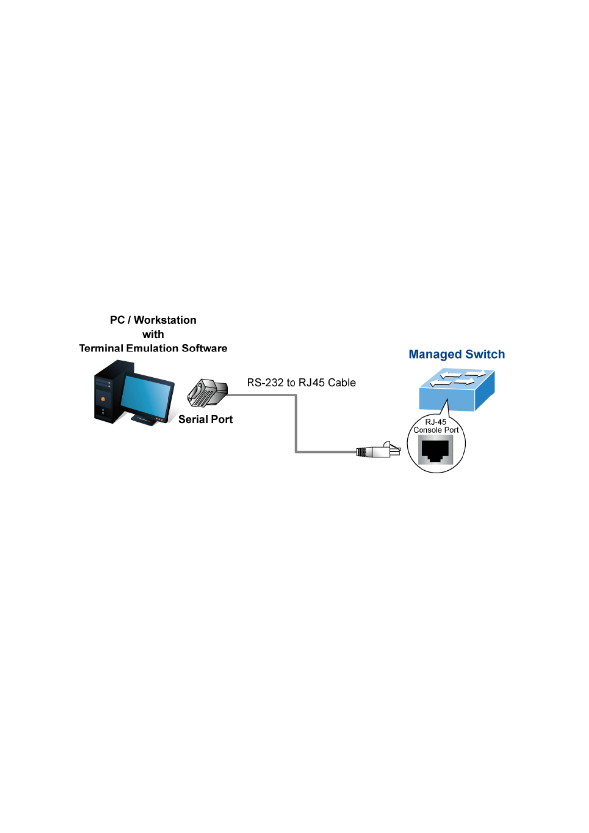
Terminal setup
To configure the system, connect a serial cable to a COM port on a PC or notebook
computer and to the RJ-45 type of serial (console) port of the managed switch.
The console port of the managed switch is a RJ-45 type, RS-232 serial port connector.
It is an interface for connecting a terminal directly. Through the console port, it provides
rich diagnostic information including IP Address setting, factory reset, port
management, link status, and system settings. Users can use the RS-232 cable in the
package and connect to the console port on the device. After the connection, users can
run any terminal emulation program (Hyper Terminal, ProComm Plus, Telix, Winterm,
and so on) to enter the startup screen of the device.
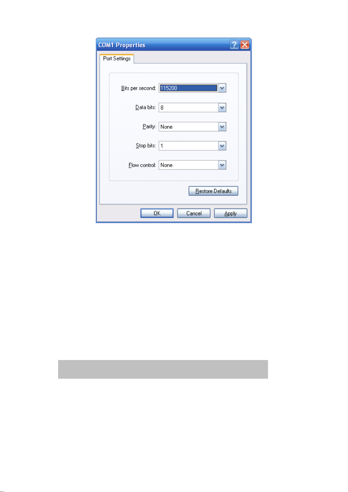
A terminal program is required to make the software connection to the managed switch.
Windows' Hyper Terminal program may be a good choice. The Hyper Terminal can be
accessed from the Start menu.
1. Click Start > Programs > Accessories, and then click Hyper Terminal.
2. When the following screen appears, make sure that the COM port is configured as
shown:
NS4750-24S-4T-4X-V2 Managed Switch Command Guide 5
Page 8
Chapter 2: Console CLI management
If required, you can change these settings after you log on. This management method
is often preferred because you can remain connected and monitor the system during
system reboots. Also, certain error messages are sent to the serial port, regardless of
the interface through which the associated action was initiated. A Macintosh or PC
attachment can use any terminal -emulation program for connecting to the terminal
serial port. A workstation attachment under UNIX can use an emulator such as TIP.
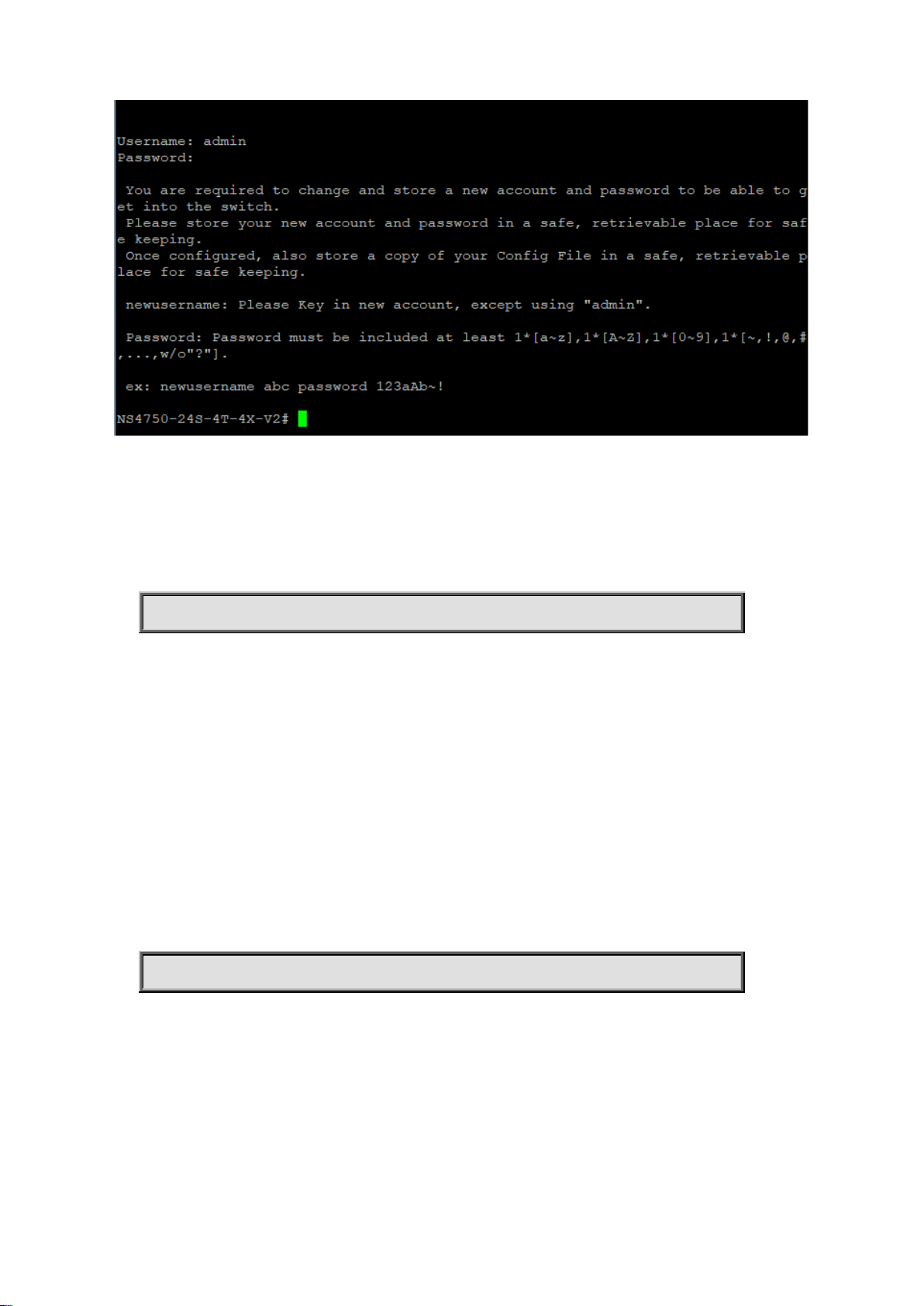
Log on to the console
After the terminal is connected to the device, power on the managed switch. “Running
testing procedures” ap pear s in the terminal display. Then, a user name and password
prompt appears. The factory default user name and password are shown as follows
and the login screen appears.
Username: admin
Password: admin
6 NS4750-24S-4T-4X-V2 Managed Switch Command Guide
Page 9
Chapter 2: Console CLI management
After logging in with the default user name and password, a new user name and
password must be configured.
newusername
Command:
newusername <username> password <password>
username Establish a new User Name Authentication
<username> New User name allows letters, numbers and underscores except
admin
password Specify the password for the user
<password > The new password is required at least 8 characters and must be
included
one lowercase letter [a~z], one uppercase letter [A~Z], one
number [0~9], and one special character [~,!,@,#,...,w/o"?"].
Default:
N/A
Usage Guide:
To change user name and password when logging with default account(admin).
Example:
To change user name and pa ssword.
Switch# newusername abc password 123aAb~!
The user can now enter commands to manage the managed switch. For a detailed
description of the commands, refer to the following chapters.
Note: For security purposes, store the new account information ain a safe location.
Configuring the IP address
The managed switch is shipped with default IP address shown below.
NS4750-24S-4T-4X-V2 Managed Switch Command Guide 7
Page 10
Chapter 2: Console CLI management
IP Address: 192.168.0.100
Subnet Mask: 255.255.255.0
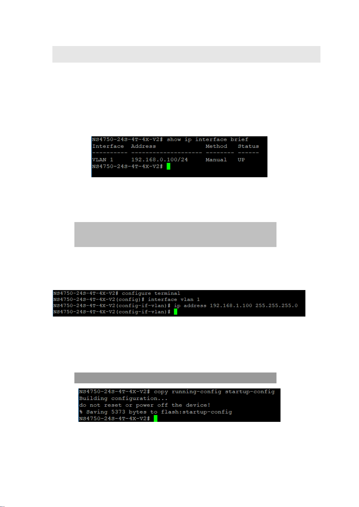
To check the current IP address or modify a new IP address for the switch, please use
the procedures as follows:
Show the current IP address
At the “#” prompt, type “show ip interface brief”. The screen displays the current IP
address and Subnet Mask as shown:
Configure the IP address
At the “#” prompt, ent er the following command and pres s Enter.
# configure terminal
(config)# interface vlan 1
(config-if-vlan)# ip address 192.168.1.100 255.255.255.0
The previous command would apply the following settings for the managed switch.
IP Address: 192.168.1.100
Subnet Mask: 255.255.255.0
At the “#” prompt, type “show ip interface brief” to check if the IP address has changed.
Store the current switch configuration
At the “#” prompt, ent er the following command and pres s Enter.
# copy running-config startup-config
If the IP is successfully configured, the managed switch applies the new IP address
setting immediately. You can access the web interface of the managed switch through
the new IP address.
8 NS4750-24S-4T-4X-V2 Managed Switch Command Guide
Page 11

Chapter 2: Console CLI management
Note: If unfamiliar with the console command or the related parameter, type “?” at any
time in the console to obtain the help description.
.
NS4750-24S-4T-4X-V2 Managed Switch Command Guide 9
Page 12
Chapter 3
Remote CLI management
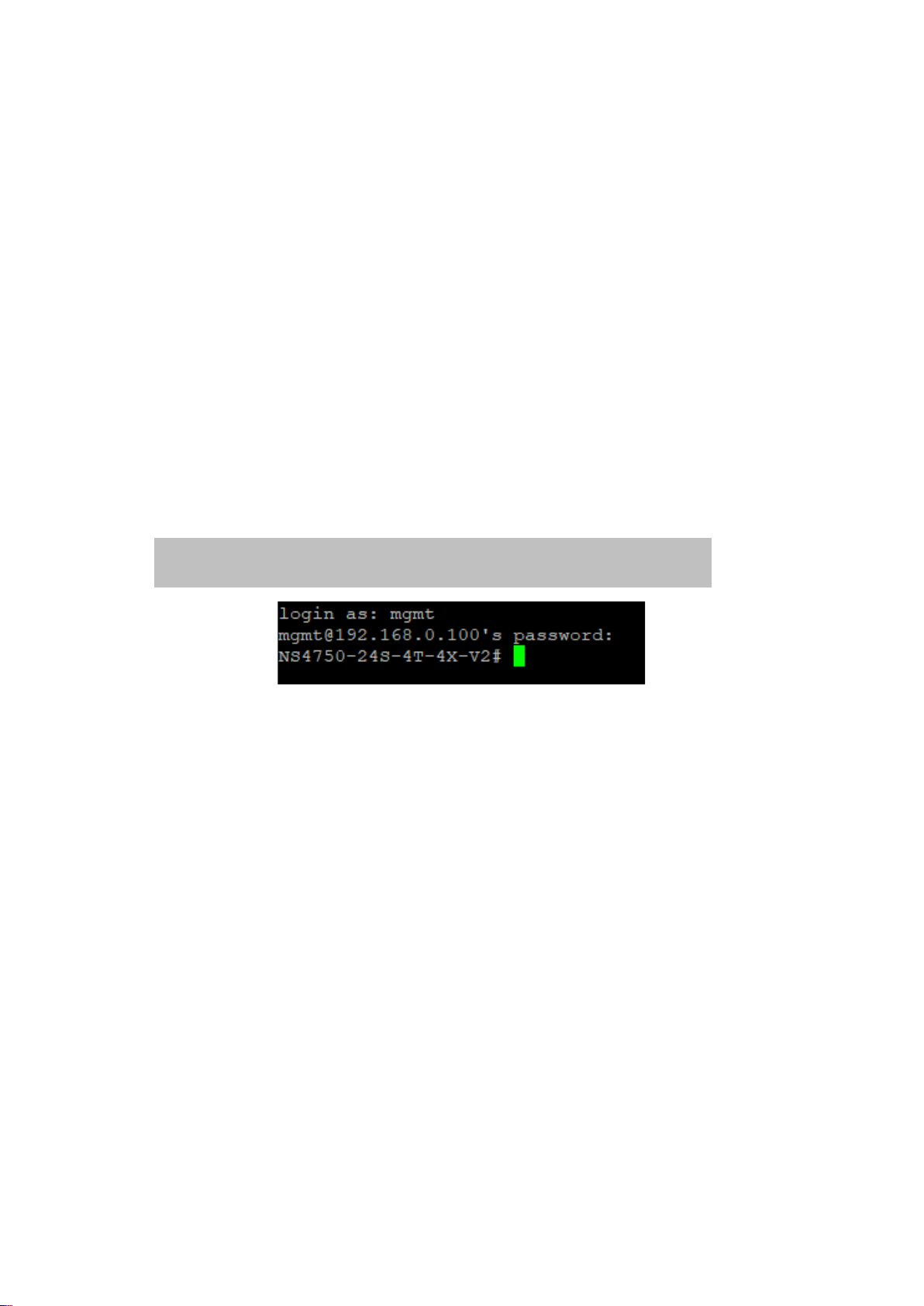
SSH login
The managed switch also supports SSH for remote management. The switch asks for a
user name and password for remote login when using telnet. Use the new username
and password.
Default IP address: 192.168.0.100
New username and password:
10 NS4750-24S-4T-4X-V2 Managed Switch Command Guide
Page 13

Chapter 4
Commands for CLI
configuration
clear
clear access management statistics
Command:
clear access management statistics
Default:
N/A
Usage Guide:
To clear the access ma nag em ent s tati s ti cs .
Example:
To clear the switch’s access management statistics.
Switch# clear access management statistics
clear access-list ace statistics
Command:
clear access-list ace st at ist ics
Default:
N/A
Usage Guide:
To clear the Access list entry statistics.
Example:
To clear the switch’s Access list entry statistics.
Switch# clear access-list ace statistics
NS4750-24S-4T-4X-V2 Managed Switch Command Guide 11
Page 14

Chapter 4: Commands for CLI configuration
clear dot1x statistics interface GigabitEthernet |
10GigabitEthernet
clear dot1x statistics interface
Command:
Default:
N/A
Usage Guide:
To clear the dot1x statistics.
Example:
To clear the switch’s GigabitEthernet 1/25 dot1x statistics.
Switch# clear dot1x statistics interface GigabitEthernet 1/25
clear eps
Command:
clear eps <Inst : uint>
<Inst : uint> The EPS instance number.
Default:
N/A
Usage Guide:
To clear the EPS instance number.
clear erps
Command:
clear erps < ERPS group numbers > statistics
Default:
N/A
Usage Guide:
To clear the ERPS group numbers statistics.
Example:
To clear the switch’s ERPS group 1 statistics.
Switch# # clear erps 1 statistics
clear erps statistics
Command:
clear erps statistics
12 NS4750-24S-4T-4X-V2 Managed Switch Command Guide
Page 15

Chapter 4: Commands for CLI configuration
Default:
N/A
Usage Guide:
To clear the ERPS statistics.
Example:
To clear the switch’s ERPS statistics.
Switch# clear erps statistics
clear ip arp
Command:
clear ip arp
Default:
N/A
Usage Guide:
To clear the ARP cache.
Example:
To clear the switch’s ARP cache.
Switch# clear ip arp
clear ip dhcp detailed statistics all
Command:
clear ip dhcp detailed statistics all
Default:
N/A
Usage Guide:
To clear the DHCP detailed statistics for all.
Example:
To clear the switch’s DHCP detailed statistics for all.
Switch# clear ip dhcp detailed statistics all
clear ip dhcp detailed statistics client
Command:
clear ip dhcp detailed statistics client
Default:
N/A
Usage Guide:
NS4750-24S-4T-4X-V2 Managed Switch Command Guide 13
Page 16

Chapter 4: Commands for CLI configuration
To clear the DHCP client statistics.
Example:
To clear the switch’s DHCP client statistics.
Switch# clear ip dhcp detailed statistics client
clear ip dhcp detailed statistics helper
Command:
clear ip dhcp detailed statistics helper
Default:
N/A
Usage Guide:
To clear the DHCP normal L2 or L3 forward statistics.
Example:
To clear the switch’s DHCP normal L2 or L3 forward statistics.
Switch# clear ip dhcp detailed statistics helper
clear ip dhcp detailed statistics server
Command:
clear ip dhcp detailed statistics server
Default:
N/A
Usage Guide:
To clear the DHCP server statistics.
Example:
To clear the switch’s DHCP server statistics.
Switch# clear ip dhcp detailed statistics server
clear ip dhcp detailed statistics snooping
Command:
clear ip dhcp detailed statistics snooping
Default:
N/A
Usage Guide:
To clear the DHCP snooping statistics.
Example:
To clear the switch’s DHCP normal L2 or L3 forward statistics.
14 NS4750-24S-4T-4X-V2 Managed Switch Command Guide
Page 17

Chapter 4: Commands for CLI configuration
Switch# clear ip dhcp detailed statistics snooping
clear ip dhcp relay statistics
Command:
clear ip dhcp relay statistics
Default:
N/A
Usage Guide:
To clear the DHCP relay statistics.
Example:
To clear the switch’s DHCP relay statistics.
Switch# clear ip dhcp relay statistics
clear ip dhcp server binding
Command:
clear ip dhcp server binding <IP>
<IP> A.B.C.D
Default:
N/A
Usage Guide:
To clear the DHCP server binding cache.
Example:
To clear the switch’s DHCP server(192.168.0.100) binding cache.
Switch# clear ip dhcp server binding 192.168.0.100
clear ip dhcp server binding automatic
Command:
clear ip dhcp server binding automatic
Default:
N/A
Usage Guide:
To clear the DHCP automatic bindings cache.
Example:
To clear the switch’s DHCP automatic bindings cache.
NS4750-24S-4T-4X-V2 Managed Switch Command Guide 15
Page 18

Chapter 4: Commands for CLI configuration
Switch# clear ip dhcp server binding automatic
clear ip dhcp server binding expired
Command:
clear ip dhcp server binding expired
Default:
N/A
Usage Guide:
To clear the DHCP expired bindings for free.
Example:
To clear the switch’s DHCP expired bindings for free.
Switch# clear ip dhcp server binding expired
clear ip dhcp server binding manual
Command:
clear ip dhcp server binding manual
Default:
N/A
Usage Guide:
To clear the DHCP server manual binding cache.
Example:
To clear the switch’s DHCP server manual binding cache.
Switch# clear ip dhcp server binding manual
clear ip igmp snooping statistics
Command:
clear ip igmp snooping statistics
Default:
N/A
Usage Guide:
To clear the IGMP snooping statistics.
Example:
To clear the switch’s IGMP snooping statistics.
Switch# clear ip igmp snooping statistics
16 NS4750-24S-4T-4X-V2 Managed Switch Command Guide
Page 19

Chapter 4: Commands for CLI configuration
clear ip igmp snooping vlan
Command:
clear ip igmp snooping vlan < vlan_list> statistics
<vlan_list> VLAN identifier(s): VID
Default:
N/A
Usage Guide:
To clear the IGMP snooping vlan < vlan_list> statistics.
Example:
To clear the switch’s IGMP snooping vlan 1 statistics.
Switch# clear ip igmp snooping vlan 1 statistics
clear ipv6 mld snooping statistics
Command:
clear ipv6 mld snooping statistics
Default:
N/A
Usage Guide:
To clear the ipv6 mld snooping statistics.
Example:
To clear the switch’s ipv6 mld snooping statistics.
Switch# clear ipv6 mld snooping statistics
clear ipv6 mld snooping vlan
Command:
clear ipv6 mld snooping vlan <vlan_list> statistics
<vlan_list> VLAN identifier(s): VID
Default:
N/A
Usage Guide:
To clear the ipv6 mld snooping statistics for specific VLAN.
Example:
To clear the switch’s ipv6 mld snooping statistics for specific VLAN 1.
Switch# clear ipv6 mld snooping vlan 1 statistics
NS4750-24S-4T-4X-V2 Managed Switch Command Guide 17
Page 20

Chapter 4: Commands for CLI configuration
clear ipv6 neighbors
Command:
clear ipv6 neighbors
Default:
N/A
Usage Guide:
To clear the ipv6 neighbors.
Example:
To clear the switch’s ipv6 neighbors.
Switch# clear ipv6 neighbors
clear lacp statistics
Command:
clear lacp statistics
Default:
N/A
Usage Guide:
To clear the lacp statistics.
Example:
To clear the switch’s lacp statistics.
Switch# clear lacp statistics
clear lldp statistics
Command:
clear lldp statistics
Default:
N/A
Usage Guide:
To clear the lldp statistics.
Example:
To clear the switch’s lldp statistics.
Switch# clear lldp statistics
18 NS4750-24S-4T-4X-V2 Managed Switch Command Guide
Page 21

Chapter 4: Commands for CLI configuration
clear logging error info
Command:
clear logging error info
Default:
N/A
Usage Guide:
To clear the logging error info.
Example:
To clear the switch’s logging error info.
Switch# clear logging error info
clear logging error warning
Command:
clear logging error warning
Default:
N/A
Usage Guide:
To clear the logging error warning.
Example:
To clear the switch’s logging error warning.
Switch# clear logging error warning
clear logging info error
Command:
clear logging info error
Default:
N/A
Usage Guide:
To clear the logging info error.
Example:
To clear the switch’s logging info error.
Switch# clear logging info error
NS4750-24S-4T-4X-V2 Managed Switch Command Guide 19
Page 22

Chapter 4: Commands for CLI configuration
clear logging info warning
Command:
clear logging info warning
Default:
N/A
Usage Guide:
To clear the logging info warning.
Example:
To clear the switch’s logging info warning.
Switch# clear logging info warning
clear logging warning error
Command:
clear logging warning error
Default:
N/A
Usage Guide:
To clear the logging warning error.
Example:
To clear the switch’s logging warning error.
Switch# clear logging warning error
clear logging warning info
Command:
clear logging warning info
Default:
N/A
Usage Guide:
To clear the logging warning info.
Example:
To clear the switch’s logging warning info.
Switch# clear logging warning info
20 NS4750-24S-4T-4X-V2 Managed Switch Command Guide
Page 23

Chapter 4: Commands for CLI configuration
clear mac address-table
Command:
clear mac address-table
Default:
N/A
Usage Guide:
To clear the mac address-table.
Example:
To clear the switch’s mac address-table.
Switch# clear mac address-table
clear mep
Command:
clear mep <Inst : uint>
<Inst : uint> The MEP instance.
Default:
N/A
Usage Guide:
To clear the MEP instance profiles.
clear mvr name
Command:
clear mvr name <MvrName : word16>
<MvrName : word16> MVR multicast VLAN name
Default:
N/A
Usage Guide:
To clear the mvr name profiles.
clear mvr statistics
Command:
clear mvr statistics
Default:
N/A
Usage Guide:
To clear the mvr statistics.
Example:
To clear the switch’s mvr statistics.
NS4750-24S-4T-4X-V2 Managed Switch Command Guide 21
Page 24

Chapter 4: Commands for CLI configuration
Switch# clear mvr statistics
clear mvr vlan
Command:
clear mvr vla n <vlan_list> statistics
<vlan_list> MVR multicast VLAN list
Default:
N/A
Usage Guide:
To clear the mvr vlan statistics for specific VLAN.
Example:
To clear the switch’s mvr vlan statistics for specific VLAN 1.
Switch# clear mvr vlan 1 statistics
clear spanning-tree detected-protocols interface *
Command:
clear spanning-tree detected-protocols interface *
Default:
N/A
Usage Guide:
To clear the spanning-tree detected-protocols for all.
Example:
To clear the switch’s spanning-tree detected-protocols for all.
Switch# clear spanning-tree detected-protocols interface *
clear spanning-tree detected-protocols interface *
Command:
clear spanning-tree detected-protocols interface *
Default:
N/A
Usage Guide:
To clear the spanning-tree detected-protocols for all.
Example:
To clear the switch’s spanning-tree detected-protocols for all.
22 NS4750-24S-4T-4X-V2 Managed Switch Command Guide
Page 25

Chapter 4: Commands for CLI configuration
clear spanning-tree detected-protocols interface
GigabitEthernet <PORT_LIST>
Switch# clear spanning-tree detected-protocols interface
GigabitEthernet 1/1
clear spanning-tree detected-protocols interface
10GigabitEthernet <PORT_LIST>
Switch# clear spanning-tree detected-protocols interface
10GigabitEthernet 1/1
Switch# clear spanning-tree detected-protocols interface *
clear spanning-tree detected-protocols interface
GigabitEthernet
Command:
<PORT_LIST> Port list in X/X-XX
Default:
N/A
Usage Guide:
To clear the spanning-tree detected-protocols for specific GigabitEthernet port.
Example:
To clear the switch’s spanning-tree detected-protocols for specific GigabitEthernet
1/1.
clear spanning-tree detected-protocols interface
10GigabitEthernet
Command:
<PORT_LIST> Port list in X/X-XX
Default:
N/A
Usage Guide:
To clear the spanning-tree detected-protocols for specific 10GigabitEthernet port.
Example:
To clear the switch’s spanning-tree detected-protocols for specific
10GigabitEthernet 1/1.
clear spanning-tree statistics interface *
Command:
clear spanning-tree statistics interface *
Default:
N/A
NS4750-24S-4T-4X-V2 Managed Switch Command Guide 23
Page 26

Chapter 4: Commands for CLI configuration
clear spanning-tree statistics interface GigabitEthernet
<PORT_LIST>
Switch# clear spanning-tree statistics interface GigabitEthernet
1/1
clear spanning-tree statistics interface 10GigabitEthernet
<PORT_LIST>
Switch# clear spanning-tree statistics interface 10GigabitEthernet
1/1
Usage Guide:
To clear the spanning-tree statistics for all.
Example:
To clear the switch’s spanning-tree statistics for all.
Switch# clear spanning-tree statistics interface *
clear spanning-tree statistics interface GigabitE thernet
Command:
<PORT_LIST> Port list in X/X-XX
Default:
N/A
Usage Guide:
To clear the spanning-tree statistics for specific GigabitEthernet port.
Example:
To clear the switch’s spanning-tree statistics for specific GigabitEthernet 1/1.
clear spanning-tree statistics interface 10GigabitEthernet
Command:
<PORT_LIST> Port list in X/X-XX
Default:
N/A
Usage Guide:
To clear the spanning-tree statistics for specific 10GigabitEthernet port.
Example:
To clear the switch’s spanning-tree statistics for specific 10GigabitEthernet 1/1.
clear statistics *
Command:
clear statistics *
Default:
24 NS4750-24S-4T-4X-V2 Managed Switch Command Guide
Page 27

Chapter 4: Commands for CLI configuration
N/A
Usage Guide:
To clear the statistics for all.
Example:
To clear the switch’s statistics for all.
Switch# clear statistics *
clear statistics GigabitEthernet
Command:
clear statistics GigabitEthernet <PORT_LIST>
<PORT_LIST> Port list in X/X-XX
Default:
N/A
Usage Guide:
To clear the statistics for specific GigabitEthernet port.
Example:
To clear the switch’s statistics for specific GigabitEthernet 1/1.
Switch# clear statistics GigabitEthernet 1/1
clear statistics 10GigabitEthernet
Command:
clear statistics 10GigabitEthernet <PORT_LIST>
<PORT_LIST> Port list in X/X-XX
Default:
N/A
Usage Guide:
To clear the statistics for specific 10GigabitEthernet port.
Example:
To clear the switch’s statistics for specific 10GigabitEthernet 1/1.
Switch# clear statistics 10GigabitEthern et 1/1
configure terminal
aaa authentication login console local
Command:
NS4750-24S-4T-4X-V2 Managed Switch Command Guide 25
Page 28

Chapter 4: Commands for CLI configuration
Switch (config)# aaa authentication login console local
Switch (config)# aaa authentication login console local radius
tacacs
aaa authentication login console local
Default:
console : local
Usage Guide:
To authenticate the local account via console only.
Example:
To authenticate the local account via console.
Switch# configure terminal
aaa authentication login console radius
Command:
aaa authentication login console radius
Default:
console : local
Usage Guide:
To authenticate the radius account via console only.
Example:
To authenticate the local and radius account via console.
Switch# configure terminal
aaa authentication login console tacacs
Command:
aaa authentication login console tacacs
Default:
console : local
Usage Guide:
To authenticate the tacacs account via console only.
Example:
To authenticate the local and radius and tacacs account via console.
Switch# configure terminal
Switch (config)# aaa authentication login console local radius
aaa authentication login http local
Command:
26 NS4750-24S-4T-4X-V2 Managed Switch Command Guide
Page 29

Chapter 4: Commands for CLI configuration
Switch (config)# aaa authentication login http local
Switch (config)# aaa authentication login http local radius
Switch (config)# aaa authentication login http local radius tacacs
aaa authentication login http local
Default:
http : local
Usage Guide:
To authenticate the local account via http only.
Example:
To authenticate the local account via http.
Switch# configure terminal
aaa authentication login http radius
Command:
aaa authentication login http radius
Default:
http : local
Usage Guide:
To authenticate the radius account via http only.
Example:
To authenticate the local and radius account via http.
Switch# configure terminal
aaa authentication login http tacacs
Command:
aaa authentication login http tacacs
Default:
http : local
Usage Guide:
To authenticate the tacacs account via http only.
Example:
To authenticate the local and radius and tacacs account via http.
Switch# configure terminal
aaa authentication login ssh local
Command:
NS4750-24S-4T-4X-V2 Managed Switch Command Guide 27
Page 30

Chapter 4: Commands for CLI configuration
Switch (config)# aaa authentication login ssh local
Switch (config)# aaa authentication login ssh local radius
Switch (config)# aaa authentication login ssh local radius tacacs
aaa authentication login ssh local
Default:
ssh : local
Usage Guide:
To authenticate the local account via ssh only.
Example:
To authenticate the local account via ssh.
Switch# configure terminal
aaa authentication login ssh radius
Command:
aaa authentication login ssh radius
Default:
ssh : local
Usage Guide:
To authenticate the radius account via ssh only.
Example:
To authenticate the local and radius account via ssh.
Switch# configure terminal
aaa authentication login ssh tacacs
Command:
aaa authentication login ssh tacacs
Default:
ssh : local
Usage Guide:
To authenticate the tacacs account via ssh only.
Example:
To authenticate the local and radius and tacacs account via console.
Switch# configure terminal
aaa authentication login telnet local
Command:
28 NS4750-24S-4T-4X-V2 Managed Switch Command Guide
Page 31

Chapter 4: Commands for CLI configuration
Switch (config)# aaa authentication login telnet local
Switch (config)# aaa authentication login telnet local radius
Switch (config)# aaa authentication login telnet local radius tacacs
aaa authentication login telnet local
Default:
telnet : local
Usage Guide:
To authenticate the local account via telnet only.
Example:
To authenticate the local account via telnet.
Switch# configure terminal
aaa authentication login telnet radius
Command:
aaa authentication login telnet radius
Default:
telnet : local
Usage Guide:
To authenticate the radius account via telnet only.
Example:
To authenticate the local and radius account via telnet.
Switch# configure terminal
aaa authentication login telnet tacacs
Command:
aaa authentication login telnet tacacs
Default:
telnet : local
Usage Guide:
To authenticate the tacacs account via telnet only.
Example:
To authenticate the local and radius and tacacs account via telnet.
Switch# configure terminal
access management
Command:
NS4750-24S-4T-4X-V2 Managed Switch Command Guide 29
Page 32

Chapter 4: Commands for CLI configuration
access management <AccessId : 1-16> <AccessVid : 1-4095>
to | We b
Switch (config)# access management 1 1 2001::7788 all
access-list ace <AceId : 1-512> action {deny, permit} | dmac-
| vid {<Vid : 1-4095>, any}
<AddrRangeStart : ipv4_addr | ipv6_addr> all | snmp | telnet |
<AccessId : 1-16> ID of access management entry
<AccessVid : 1-4095> The VLAN ID for the access management entry
<AddrRangeStart : ipv4_addr> Start IPv4 address
<AddrRangeStart : ipv6_addr> Start IPv6 address
all All services
snmp SNMP service
telnet TELNET/SSH service
to End address of the range
web Web service
Default:
access management : disable
Usage Guide:
To enable t he acce ss m anag emen t profile to allow SNMP / Telnet / HTTP
services.
Example:
To create a Profile 1 enabling all services for VLAN 1 (IPv6 address 2001::7788) .
Switch# configure terminal
access-list ace
Command:
type {any, broadcast, multicast, unicast} | frametype {any,
arp, etype, ipv4, ipv4-icmp, ipv4-tcp, ipv4-udp, ipv6, ipv6icmp, ipv6-tcp, ipv6-udp} | ingress {any, interface
10GigabitEthernet | GigabitEthernet <PORT_ID>} | logging
{disable, next, policy, rate-limiter, shutdown, tag-priority, vid}
| next {<AceId : 1-512>, last}| policy <PolicyId : 0-255> | ratelimiter {<RateLimiterId : 1-16>, disable} | redirect {disable,
interface 10GigabitEthernet | GigabitEthernet <PORT_ID>} |
tag-priority {0-1, 0-3, 2-3, 4-5, 4-7, 6-7, <TagPriority : 0-7>, any}
<AceId : 1-512> ACE ID
action Access list action
dmac-typ e The type of destination MAC address
frametype Frame type
ingress Ingress
logging Logging frame information. Note: The logging feature only
works when the packet length is less than 1518 (without
VLAN tags) and the System Log memory size and logging rate
are limited.
next Insert the current ACE before the next ACE ID
30 NS4750-24S-4T-4X-V2 Managed Switch Command Guide
Page 33

Chapter 4: Commands for CLI configuration
limiter 1 tag-priority 1 vid 1
access-list ace update <AceId : 1-512> action {deny, permit} |
| vid {<Vid : 1-4095>, any}
policy Policy
rate-limiter Rate limiter
redirect Redirect frame to specific port
shutdown Shutdown incoming port. The shutdown feature only works
when the packet length is less than 1518 (without VLAN
tags).
tag-priority Tag priority
vid VID field
Default:
N/A
Usage Guide:
To create and set up a profile for the access list.
Example:
To set a Profile 1 up (action: permit, dmac-type: unicast, frametype: ipv4-icmp,
ingress: any, logging: disable, policy: 1, rate-limiter: 1, tag-priority: 1. vid: 1).
Switch# configure terminal
Switch (config)# access-list ace 1 action permit dmac-type unicast
frametype ipv4-icmp ingress any logging disable policy 1 rate-
access-list ace update
Command:
dmac-type {any, broadcast, multicast, unicast} | frametype
{any, arp, etype, ipv4, ipv4-icmp, ipv4-tcp, ipv4-udp, ipv6,
ipv6-icmp, ipv6-tcp, ipv6-udp} | ingress {any, interface
10GigabitEthernet | GigabitEthernet <PORT_ID>} | logging
{disable, next, policy, rate-limiter, shutdown, tag-priority, vid}
| next {<AceId : 1-512>, last}| policy <PolicyId : 0-255> | ratelimiter {<RateLimiterId : 1-16>, disable} | redirect {disable,
interface 10GigabitEthernet | GigabitEthernet <PORT_ID>} |
tag-priority {0-1, 0-3, 2-3, 4-5, 4-7, 6-7, <TagPriority : 0-7>, any}
<AceId : 1-512> ACE ID
action Access list action
dmac-typ e The type of destination MAC address
frametype Frame type
ingress Ingress
logging Logging frame information. Note: The logging feature only
works when the packet length is less than 1518 (without
VLAN tags) and the System Log memory size and logging rate
are limited.
next Insert the current ACE before the next ACE ID
policy Policy
rate-limiter Rate limiter
redirect Redirect frame to specific port
NS4750-24S-4T-4X-V2 Managed Switch Command Guide 31
Page 34

Chapter 4: Commands for CLI configuration
any
access-list rate-limiter <RateLimiter Li st : 1~ 16> pps
<PpsRate : 0-131071>
Switch (config)# access-list rate-limiter 1 pps 10000
shutdown Shutdown incoming port. The shutdown feature only works
when the packet length is less than 1518 (without VLAN
tags).
tag-priority Tag priority
vid VID field
Default:
N/A
Usage Guide:
To update the specific pro file for the access list.
Example:
Original:
Profile 1 (action: permit, dmac-type: unicast, frametype: ipv4-icmp, ingress: any,
logging: disable, policy: 1, rate-limiter: 1, tag-priority: 1. vid: 1).
Updated:
Profile 1 (action: deny, dmac-type: any, frametype: ipv4-icmp, ingress: any,
logging: disable, policy: 1, rate-limiter: 1, tag-priority: 1. vid: 1).
Switch# configure terminal
Switch (config)# access-list ace update 1 action deny dmac-type
access-list rate-limiter
Command:
<RateLimiterList : 1~16> Rate limiter ID
<PpsRate : 0-131071> Rate value
Default:
0
Usage Guide:
To set pps rate for specific rate-limiter ID.
Example:
To set pps rate(10000 pps) for specific rate-limiter ID 1.
Switch# configure terminal
access-list rate-limite r pps
Command:
access-list rate-limiter pps <PpsRate : 0-131071>
<PpsRate : 0-131071> Rate value
Default:
32 NS4750-24S-4T-4X-V2 Managed Switch Command Guide
Page 35

Chapter 4: Commands for CLI configuration
Switch (config)# access-list rate-limiter pps 100
Switch (config)# access-list rate-limiter pps 100
Enter TEXT message. End with the character '1'.
0
Usage Guide:
To set pps rate for all rate-limiter ID.
Example:
To set pps rate(10000 pps) for all rate-limiter ID.
Switch# configure terminal
aggregation mode
Command:
aggregation mode dmac | ip | port | smac
dmac Destination MAC affect s the distribution
ip IP address affects the distribution
port IP port affects the distribution
smac Source MAC affects the distribution
Default:
SMAC : Enabled
DMAC : Disabled
IP : Enabled
Port : Enabled
Usage Guide:
To configure static aggregation mode type.
Example:
To configure static aggregation mode type with Destination MAC affects the
distribution and Source MAC affects the distribution only.
Switch# configure terminal
banner
Command:
banner <LINE>
<LINE> c banner-text c, where 'c' is a delimiting character
Default:
N/A
Usage Guide:
To configure banner-text.
Example:
To configure banner-text with word “ddddd”.
Switch# configure terminal
Switch (config)# banner 1
NS4750-24S-4T-4X-V2 Managed Switch Command Guide 33
Page 36

Chapter 4: Commands for CLI configuration
ddddd
1
Username:
1
Username: admin
#
Telnet 192.168.0.100
ddddd
banner exec
Command:
banner login <LINE>
<LINE> c banner-text c, where 'c' is a delimiting character
Default:
N/A
Usage Guide:
To configure login banner-text.
Example:
To configure login banner-text with word “wwwwwwwwww”.
Telnet 192.168.0.100:
banner login
Command:
<LINE> c banner-text c, where 'c' is a delimiting character
Default:
N/A
Usage Guide:
To configure login banner-text.
Example:
Switch# configure terminal
Switch (config)# b anner exec 1
Enter TEXT message. End with the character '1'.
gggggg
Password:
gggggg
banner login <LINE>
34 NS4750-24S-4T-4X-V2 Managed Switch Command Guide
Page 37

Chapter 4: Commands for CLI configuration
1
Press ENTER to get started
Password:
1
ffffff
Username:
To configure login banner-text with word “wwwwwwwwww”.
Switch# configure terminal
Switch (config)# banner logi n 1
Enter TEXT message. End with the character '1'.
wwwwwwwwww
Console:
wwwwwwwwww
Username: admin
banner motd
Command:
banner motd <LINE>
<LINE> c banner-text c, where 'c' is a delimiting character
Default:
N/A
Usage Guide:
To configure motd banner-text.
Example:
To configure motd banner-text with word “ffffff”.
Switch# configure terminal
Switch (config)# banner motd 1
Enter TEXT message. End with the character '1'.
ffffff
Console:
Press ENTER to get started
NS4750-24S-4T-4X-V2 Managed Switch Command Guide 35
Page 38

Chapter 4: Commands for CLI configuration
clock summer-time <WORD> date <Monthstart: 1-12>
<Timeend: hh: mm > <Offset minutes: 1-1440 >
2013 8:8 60
Switch (config)# clock timezone 1 -15
clock summer-time
Command:
<Daystart: 1-31> <Yearstart: 1-12> <Timestart: hh:mm >
<Monthend: 1-12> <Dayend: 1-31> <Yearend: 1-12>
Default:
N/A
Usage Guide:
To set daylight saving.
Example:
To set daylight saving (Started time: Feb, 3. 2013 8:8AM, End time: Dec, 31. 2013
8:8AM, Offset tim e: 60 minutes).
Switch# configure terminal
Switch (config)# clock summer-time 1 date 2 3 2013 8:8 12 31
clock timezone
Command:
clock timezone <WORD> <timezone: -23-23>
<WORD> name of time zone
Default:
0
Usage Guide:
To set timezone.
Example:
To set timezone (GMT -15) with profile 1.
Switch# configure terminal
default access-list rate-limiter
Command:
default access-list rate-limiter <RateLimiterId : 1-16>
<RateLimiterId : 1-16> Rate limiter ID
Default:
0
Usage Guide:
To default the Rate limiter.
Example:
To default the Rate limiter ID 1.
36 NS4750-24S-4T-4X-V2 Managed Switch Command Guide
Page 39

Chapter 4: Commands for CLI configuration
Switch (config)# default access-list rate-limiter 1
Switch (config)# dot1x authentication timer inactivity 147
Switch (config)# dot1x authentication timer re-auth ent i cate 777
Switch# configure terminal
dot1x authentication timer inactivity
Command:
dot1x authentication timer inactivity <10-1000000>
Default:
Aging period: 300
Usage Guide:
To set the Aging period for Network Access Server.
Example:
To set the Aging period (147 seconds).
Switch# configure terminal
dot1x authentication timer re-authenticate
Command:
dot1x authentication timer re-authenticate <1-3600>
Default:
Re-authenticated Period: 3600
Usage Guide:
To set the Re-authenticated Period for Network Access Server.
Example:
To set the Re-authenticated Period (777 seconds).
Switch# configure terminal
dot1x feature
Command:
dot1x feature guest-vlan | radius-qos | radius-vlan
Default:
Disable
Usage Guide:
To enable the guest-vlan, radius-qos, radius-vlan for Network Access Server
Example:
To enable the guest-vlan, radius-qos, radius-vlan for Network Access Server.
NS4750-24S-4T-4X-V2 Managed Switch Command Guide 37
Page 40

Chapter 4: Commands for CLI configuration
Switch (config)# dot1x authentication timer re-auth ent i cate 777
Switch (config)# dot1x guest-vlan 2
Switch (config)# dot1x guest-vlan supplicant
Switch# configure terminal
dot1x guest-vlan
Command:
dot1x guest-vlan <1-4095>
<1-4095> Guest VLAN ID used when entering the Guest VLAN.
Default:
1
Usage Guide:
To set the value of guest-vlan for Network Access Server
Example:
To set the value of guest-vlan(2) for Network Access Server
Switch# configure terminal
dot1x guest-vlan supplicant
Command:
dot1x guest-vlan supplicant
supplicant The switch remembers if an EAPOL frame has been received on the port
for the life-time of the port. Once the switch considers whether to enter
the Guest VLAN, it will first check if this option is enabled or disabled.
Default:
Disable
Usage Guide:
To allow all frames automatically entering guest-vlan for Network Access Server
Example:
To allow all frames automatically entering guest-vlan for Network Access Server
Switch# configure terminal
dot1x max-reauth-req
Command:
dot1x max-reauth-req <1-255>
Default:
2
Usage Guide:
38 NS4750-24S-4T-4X-V2 Managed Switch Command Guide
Page 41

Chapter 4: Commands for CLI configuration
Switch (config)# dot1x max-reauth-req 78
Switch (config)# dot1x system-auth-control
Switch (config)# dot1x timeout quiet-period 12
To define 802.1X re-authentication frequency for Network Access Server
Example:
To define 802.1X re-authentication frequency with 78 times for Network Access
Server
Switch# configure terminal
dot1x system-auth-control
Command:
dot1x system-auth-control
Default:
Disable
Usage Guide:
To enable 802.1X service for Networ k A ccess Server
Example:
To enable 802.1X service for Networ k A ccess Server
Switch# configure terminal
dot1x timeout quiet-period
Command:
dot1x timeout quiet-period <10-1000000>
quiet-period Time in seconds before a MAC-address that fail e d authentication
gets a new authentication chance.
Default:
10
Usage Guide:
To configure 802.1X hold time for Network A ccess Server
Example:
To configure 802.1X hold time(12 seconds) for Network Access Server
Switch# configure terminal
dot1x timeout tx-period
Command:
dot1x timeout tx-period <1-65535>
tx-period The time between EAPOL re t rans mis si o ns .
Default:
30
NS4750-24S-4T-4X-V2 Managed Switch Command Guide 39
Page 42

Chapter 4: Commands for CLI configuration
Switch (config)# dot1x timeout tx-period 45
#
Usage Guide:
To configure 802.1X EPOAL timeout for Networ k A ccess Server
Example:
To configure 802.1X EPOAL timeout (45 seconds) for Network A ccess Server
Switch# configure terminal
enable password
Command:
enable password <WORD>
<WORD> The UNENCRYPTED (cleartext) password.
Default:
Disable
Usage Guide:
To configure enable password for user
Example:
To configure enable password(admin) for user
Switch# configure terminal
Switch (config)# enable password admin
Press ENTER to get started
Username:
Password:
> enable
Password: *****
enable password level
Command:
enable password level <1-15> <WORD>
<1-15> Level number
<WORD> The UNENCRYPT ED (cleartext) password.
Default:
Disable
Usage Guide:
To configure enable password and specific level for user
40 NS4750-24S-4T-4X-V2 Managed Switch Command Guide
Page 43

Chapter 4: Commands for CLI configuration
#
#
Example:
To configure enable password(admin) and specific level(15) for user
Switch# configure terminal
Switch (config)# enable password level 15 admin
Press ENTER to get started
Username:
Password:
> enable
Password: admin
enable secret
Command:
enable secret 0 | 5 level <1-15> <WORD>
0 Specifies an UNENCRYPTED password will follow
5 Specifies an ENCRYPTED secret will follow
<1-15> Level number
<WORD> The UNENCRYPTED (cleartext) / ENCRYPTED(MD5) password.
Default:
Disable
Usage Guide:
To configure enable password to encrypted secret in the system configurations
and specific level for user
Example:
To configure enable password(cisco) to encrypted secret in the system
configurations and specific level(15) for user
Switch# configure terminal
Switch (config)# enable secret 0 level 15 cisco
# show running-config
Building configuration...
enable secret 5 level 15
FC89368B9513DE0760290BCE9A1DA90A
……………
Press ENTER to get started
Username:
Password:
> enable
Password: cisco
NS4750-24S-4T-4X-V2 Managed Switch Command Guide 41
Page 44

Chapter 4: Commands for CLI configuration
#
Switch (config)# erps 1 guard 178
end
Command:
end
Default:
N/A
Usage Guide:
To level the configure terminal mode
Example:
To level the configure terminal mode
Switch# configure terminal
Switch (config)# end
erps <1-64> guard
Command:
erps <1-64> guard <10-2000>
<1-64> ERPS group number
<10-2000> Guard time in ms
Default:
500
Usage Guide:
To configure the Guard Time for ERPS.
Example:
To configure the Guard Time(178 ms) for ERPS(Profile 1)
Switch# configure terminal
erps <1-64> holdoff
Command:
erps <1-64> holdoff < 0-10000>
<1-64> ERPS group number
< 0-10000> Holdoff time in ms
Default:
0
Usage Guide:
To configure the Hold Off Time for ERPS
Example:
To configure the Hold Off Time (178 ms) for ERPS(Profile 1)
42 NS4750-24S-4T-4X-V2 Managed Switch Command Guide
Page 45

Chapter 4: Commands for CLI configuration
Switch (config)# erps 1 holdoff 900
erps <1-64> major port0 interface {10GigabitEthernet,
[ interconnect ]
1/1 port1 interface GigabitEthernet 1/2
erps <1-64> mep port0 sf <p0_sf: 1-100> aps <p0_aps: 1-100>
port1 sf <p1_sf: 1-100> aps <p1_aps: 1-100>
Switch (config)# erps 1 mep port0 sf 2 aps 1 port1 sf 4 aps 3
Switch# configure terminal
erps <1-64> major
Command:
GigabitEthernet} <PORT0_ID> port1 interface
{10GigabitEthernet, GigabitEthernet} <PORT1_ID>
<1-64> ERPS group number
interconnect Major ring is interconnected
Default:
0
Usage Guide:
To create a profile and configure the Major ERPS inter fa ce por t 0, port 1.
Example:
To create a profile 1 and configure the Major ERPS interface port
0(GigabitEthernet 1/1), port 1(GigabitE the rnet 1/2) without interconnected
mode
Switch# configure terminal
Switch (config)# erps 1 major port0 interface GigabitEthernet
erps <1-64> mep
Command:
<1-64> ERPS group number
<p0_sf: 1-100> Index of Port 0 SignalFail MEP
<p0_aps: 1-100> Index of Port 0 APS MEP
<p1_sf: 1-100> Index of Port 1 SignalFail MEP
<p1_aps: 1-100> Index of Port 1 APS MEP
Default:
0
Usage Guide:
To configure ERPS Instance Data for specific ERPS profile.
Example:
To configure ERPS Instance Data(Port0: SF MEP = 2, APS MEP = 1. Port1: SF
MEP = 4, APS MEP = 3) for specific ERPS profile(1).
Switch# configure terminal
NS4750-24S-4T-4X-V2 Managed Switch Command Guide 43
Page 46

Chapter 4: Commands for CLI configuration
Switch (config)# erps 1 rpl neighbor port0
Switch (config)# erps 1 rpl owner port0
erps <1-64> sub port0 interface {10GigabitEthernet,
{interconnect <major_ring_id: 1-64> [ virtual-channel ] } }
erps <1-64> rpl neighbor
Command:
erps <1-64> rpl neighbor { port0 | port1 }
port0 ERPS Port 0 interface
port1 ERPS Port 1 interface
Default:
N/A
Usage Guide:
To configure Ring Protection Link Neighbor Role for specific ERPS interface.
Example:
To configure Ring Protection Link Neighbor Role for specific ERPS interface..
Switch# configure terminal
erps <1-64> rpl owner
Command:
erps <1-64> rpl owner { port0 | port1 }
port0 ERPS Port 0 interface
port1 ERPS Port 1 interface
Default:
N/A
Usage Guide:
To configure Ring Protection Link Owner Role for specific ERPS interface.
Example:
To configure Ring Protection Link Owner Role for specific ERPS interface..
Switch# configure terminal
erps <1-64> sub
Command:
GigabitEthernet} <PORT0_ID> { { port0 interface
{10GigabitEthernet, GigabitEthernet} <PORT1_ID> },
<1-64> ERPS group number
interconnect Sub ring is interconnected
<major_ring_id: 1-64> Major ring group number
virtual-channel Enable virtual channel for sub-ring
Default:
0
44 NS4750-24S-4T-4X-V2 Managed Switch Command Guide
Page 47

Chapter 4: Commands for CLI configuration
port1 interface GigabitEthernet 1/6
interconnect 1 virtual-channel
Switch (config)# erp s 1 topology-change propagate
Usage Guide:
To create a profile and configure the Sub ERPS i nterface port 0, port 1.
Example 1:
To create a profile 3 and configure the Sub ERPS interface port
0(GigabitEthernet 1/5), port 1(Gigabi tE the rnet 1/6) without interconnected
mode and Major RIng group and virtual-channel
Switch# configure terminal
Switch (config)# erps 3 sub port0 interface GigabitEthernet 1/5
Example 2:
To create a profile 2 and configure the Sub ERPS interface port
0(GigabitEthernet 1/3), port 1(Gigabi tE the rnet 1/4) with inter connected mode
and Major RIng group 1 and virtual-channel
Switch# configure terminal
Switch (config)# er p s 1 sub port0 interface GigabitEthernet 1/3
erps <1-64> topology-change propagate
Command:
erps <1-64> topology-change propagate
<1-64> ERPS group number
topology-change Topology Change
propagate Propagate
Default:
N/A
Usage Guide:
To configure topology change notification (TCN) propagation for the specific
profile.
Example:
To configure topology change notification (TCN) propagation for the specific
profile 1
Switch# configure terminal
erps <1-64> topology-change propagate
Command:
erps <1-64> version 1 | 2
<1-64> ERPS group number
version Version
Default:
V2
NS4750-24S-4T-4X-V2 Managed Switch Command Guide 45
Page 48

Chapter 4: Commands for CLI configuration
Switch (config)# er p s 1 version 1
Switch (config)# erps 1 vlan add 5-8
#
Usage Guide:
To configure ERPS version number for the specific profile.
Example:
To configure ERPS version 1 for the specific profile 1.
Switch# configure terminal
erps <1-64> vlan
Command:
erps <1-64> vlan { none | [ add | remove ] <vlans> }
<1-64> ERPS group number
<vlan_list> List of VLANs
add Add to set of included VLANs
none Do not include any VLANs
remove Remove from set of included VLANs
Default:
V2
Usage Guide:
To configure ERPS VLANs for the specific profile.
Example:
To configure ERPS VLANs(VLAN5 - VLAN8) for the specific profile 1.
Switch# configure terminal
exit
Command:
exit
Default:
N/A
Usage Guide:
To exit configure terminal mode.
Example:
To exit configure terminal mode.
Switch# configure terminal
Switch (config)# exit
help
Command:
46 NS4750-24S-4T-4X-V2 Managed Switch Command Guide
Page 49

Chapter 4: Commands for CLI configuration
2. Partial help is provided when an abbreviated argument is
(e.g. 'show pr?'.)
IFSbestswitch(config)#
interface * | 10GigabitEthernet <port_type_list> |
help
Default:
N/A
Usage Guide:
To explain how to use commands.
Example:
To explain how to use commands.
Switch# configure terminal
Switch (config)# help
Help may be requested at any point in a command by entering
a question mark '?'. If nothing matches, the help list will
be empty and you must back up until entering a '?' showing the
available options.
Two styles of help are provided:
1. Full help is available when you are ready to enter a
command argument (e.g. 'show ?') and describes each possible
argument.
entered and you want to know what arguments match the input
hostname
Command:
hostname < WORD >
< WORD > This system's network name
Default:
N/A
Usage Guide:
To configure switch’s hostname.
Example:
To configure switch’s hostname with “IFSbestswitch”
Switch# configure terminal
Switch (config)# hostname IFSbestswitch
interface * | 10GigabitEthernet | GigabitEthernet
Command:
NS4750-24S-4T-4X-V2 Managed Switch Command Guide 47
Page 50

Chapter 4: Commands for CLI configuration
GigabitEthernet <port_type_list>
Switch (config-if) #
Switch (config-if) # access-list action permit
Switch (config)# interface GigabitEthernet X/X
* All switches or All ports
GigabitEthernet 1 Gigabit Ethernet Port
10GigabitEthernet 10 Gigabit Ethernet Port
Default:
N/A
Usage Guide:
To enter the interface mode.
Example:
To enter the interface 10GigabitEthernet 1/2
Switch# configure terminal
Switch (config)# in t erface 10GigabitEthernet 1/2
access-list action permit
Command:
access-list action permit
action Access list action
Default:
Permit
Usage Guide:
To configure Permit for the ACL action.
Example:
To configure Permit ACL ac ti on for the GigabitEthernet X/X.
Switch# configure terminal
Switch (config)# interface GigabitEthernet X/X
access-list action deny
Command:
access-list action deny
action Access list action
Default:
Deny
Usage Guide:
To configure Deny for the ACL action.
Example:
To configure Deny ACL action for the GigabitEthernet X/X.
Switch# configure terminal
48 NS4750-24S-4T-4X-V2 Managed Switch Command Guide
Page 51

Chapter 4: Commands for CLI configuration
Switch (config-if) # access-list action deny
Switch (config-if) # access-list logging
Switch (config-if) # access-list policy 1
access-list logging
Command:
access-list logging
logging Logging frame information. Note: The logging feature only works when
the packet length is less than 1518 (without VLAN tags) and the
System Log memory size and logging rate is limited.
Default:
Disable
Usage Guide:
To enable Logging function for the ACL.
Example:
To enable ACL Logging function for the GigabitEthernet X/X.
Switch# configure terminal
Switch (config)# interface GigabitEthernet X/X
access-list policy
Command:
access-list policy <PolicyId : 0-255>
policy Policy
<PolicyId : 0-255> Policy ID
Default:
Policy ID: 0
Usage Guide:
To configure Policy ID for the ACL.
Example:
To configure ACL Policy ID 1 for the GigabitEthernet X/X.
Switch# configure terminal
Switch (config)# interface GigabitEthernet X/X
access-list port-state
Command:
access-list port-state
port-state Re-enable shutdown port that was shutdown by access-list module
Default:
Enable
Usage Guide:
To enable Port-state function for the ACL.
NS4750-24S-4T-4X-V2 Managed Switch Command Guide 49
Page 52

Chapter 4: Commands for CLI configuration
Switch (config-if) # access-list port-state
Switch (config-if) # access-list rate-limiter 1
access-list redirect interface 10GigabitEthernet
<port_type_list> | GigabitEthernet <port_type_list>
GigabitEthernet 1/2
Example:
To configure ACL Port-state function for the GigabitEthernet X/X.
Switch# configure terminal
Switch (config)# interface GigabitEthernet X/X
access-list rate-limiter
Command:
access-list rate-limiter <RateLimiterId : 1-16>
rate-limiter Rate limiter
<RateLimiterId : 1-16> Rate limiter ID
Default:
Disable
Usage Guide:
To apply Rate Limiter ID for the ACL.
Example:
To apply ACL Rate Limiter ID 1 for the GigabitEthernet X/X.
Switch# configure terminal
Switch (config)# interface GigabitEthernet X/X
access-list redirect interface
Command:
redirect Redirect frame to specific port
Default:
Disable
Usage Guide:
To redirect frames to specific Port.
Example:
To redirect GigabitEthernet X/X frames to GigabitEthernet 1/2.
Switch# configure terminal
Switch (config)# interface GigabitEthernet X/X
Switch (config-if) # access-list redirect interface
access-list shutdown
Command:
access-list shutdown
shutdown Shut down incoming port. The shutdown feature only works when the
packet length is less than 1518 (without VLAN tags).
50 NS4750-24S-4T-4X-V2 Managed Switch Command Guide
Page 53

Chapter 4: Commands for CLI configuration
Switch (config-if) # access-list shutdown
Switch (config-if) # aggregation group 7
Switch (config-if) # description IPTV_Port
Default:
Disable
Usage Guide:
To enable Shutdown function for the ACL.
Example:
To enable ACL Shutdown function for the GigabitEthernet X/X.
Switch# configure terminal
Switch (config)# interface GigabitEthernet X/X
aggregation group
Command:
aggregation group <uint>
aggregation Create an aggregation
group Create an aggregation group
<uint> The aggregation group id
Default:
N/A
Usage Guide:
To configure aggregation group.
Example:
To configure aggregation group 7 for the GigabitEthernet X/X.
Switch# configure terminal
Switch (config)# interface GigabitEthernet X/X
description
Command:
description <string>
description Port description
<string> specifies a comment or a description of the port to assist the user.
(Length: 1-12 characters)
Default:
N/A
Usage Guide:
To configure port description.
Example:
To configure port description (IPTV_Port) for the GigabitEthernet X/X.
Switch# configure terminal
Switch (config)# interface GigabitEthernet X/X
NS4750-24S-4T-4X-V2 Managed Switch Command Guide 51
Page 54

Chapter 4: Commands for CLI configuration
http : local
Switch (config-if) # dot1x guest-vlan
dot1x port-control auto | force-authorized | forceunauthorized | mac-based | multi | single
do
Command:
do < exec commands >
do To run exec commands in config mode
Default:
N/A
Usage Guide:
To run exec commands in configure terminal mode
Example:
To run “show aaa” in configure terminal mode.
Switch# configure terminal
Switch (config)# interface GigabitEthernet X/X
Switch (config-if) # do show aaa
console : local
telnet : local
ssh : local
dot1x guest-vlan
Command:
dot1x guest-vlan
dot1x IEEE Standard for por t-based Network Access Control
guest-vlan Enables/disables guest VLA N
Default:
Disable
Usage Guide:
To enable Guest VLAN
Example:
To enable Guest VLAN for GigabitEthernet X/X.
Switch# configure terminal
Switch (config)# interface GigabitEthernet X/X
dot1x port-control
Command:
dot1x IEEE Stand ar d for port-based Network Access Control
port-control Sets the port security state.
auto Port-based 802.1X Authentication
force-authorized Port access is allowed
force-unauthorized Port access is not allowed
mac-based Switch authenticates on behalf of the client
52 NS4750-24S-4T-4X-V2 Managed Switch Command Guide
Page 55

Chapter 4: Commands for CLI configuration
Switch (config-if) # dot1x port-control auto
Switch (config-if) # dot1x radius-qos
Switch (config-if) # dot1x radius-vlan
multi Mul tiple Host 802.1X Authenticatio n
single Single Host 802.1X Authentication
Default:
Force-authorized
Usage Guide:
To configure Port-control mode for 802.1X
Example:
To configure Port-Based 802.1X(Auto) mode for GigabitEthernet X/X.
Switch# configure terminal
Switch (config)# interface GigabitEthernet X/X
dot1x radius-qos
Command:
dot1x radius-qos
dot1x IEEE Stand ar d for port-based Network Access Control
radius-qos Enables/disabl es per-port state of RADIUS-assigned QoS.
Default:
Disable
Usage Guide:
To enable RADIUS-assigned QoS for 802.1X
Example:
To enable RADIUS-assigned QoS for GigabitEthernet X/X.
Switch# configure terminal
Switch (config)# interface GigabitEthernet X/X
dot1x radius-vlan
Command:
dot1x radius-vlan
dot1x IEEE Stand ar d for port-based Network Access Control
radius-vlan Enables/disables per-port state of RADIUS-assigned VLAN.
Default:
Disable
Usage Guide:
To enable RADIUS-assigned VLAN for 802.1X
Example:
To enable RADIUS-assigned VLAN for GigabitEthernet X/X.
Switch# configure terminal
Switch (config)# interface GigabitEthernet X/X
NS4750-24S-4T-4X-V2 Managed Switch Command Guide 53
Page 56

Chapter 4: Commands for CLI configuration
Switch (config-if) # dot1x re-authenticate
Switch (config-if) # duplex auto
dot1x re-authenticate
Command:
dot1x re-authenticate
dot1x IEEE Stand ar d for port-based Network Access Control
re-authenticate Refresh (restart) 802.1X authentication process.
Default:
N/A
Usage Guide:
To restart 802.1X authentication process.
Example:
To restart 802.1X authentication process for GigabitEthernet X/X.
Switch# configure terminal
Switch (config)# interface GigabitEthernet X/X
duplex
Command:
duplex auto | full | half
duplex Interface duplex
auto Auto negotiation of duplex mode.
full Forced full duplex.
half Forced half duplex.
Default:
Auto
Usage Guide:
To configure duplex mode for interface.
Example:
To configure auto duplex mode for GigabitEthernet X/X.
Switch# configure terminal
Switch (config)# interface GigabitEthernet X/X
end
Command:
end
end Go back to EXEC mode
Default:
Auto
Usage Guide:
To back to EXEC mode
Example:
To back to EXEC mode
54 NS4750-24S-4T-4X-V2 Managed Switch Command Guide
Page 57

Chapter 4: Commands for CLI configuration
Switch#
Switch (config-if) # excessive-restart
Switch (config)#
Switch# configure terminal
Switch (config)# interface GigabitEthernet X/X
Switch (config-if) # end
excessive-restart
Command:
excessive-restart
excessive-restart Restart backoff algorithm after 16 collisions (No excessive-
restart means discard f rame a ft er 16 collisions)
Default:
Discard
Usage Guide:
To enable Backoff Algorithm for the specific interface
Example:
To enable Backoff Algorithm for the GigabitEthernet X/X.
Switch# configure terminal
Switch (config)# interface GigabitEthernet X/X
exit
Command:
exit
exit Exit from current mode
Default:
None
Usage Guide:
To exit current mode
Example:
To exit current mode.
Switch# configure terminal
Switch (config)# interface GigabitEthernet X/X
Switch (config-if) # exit
flowcontrol
Command:
flowcontrol off | on
flowcontrol Traffic flow control.
off Disable flow control.
on Enable flow control .
NS4750-24S-4T-4X-V2 Managed Switch Command Guide 55
Page 58

Chapter 4: Commands for CLI configuration
Switch (config-if) # flowcontrol on
Switch (config-if) # ip arp inspection check-vlan
Default:
Disable
Usage Guide:
To enable Flow-control for specific interface
Example:
To enable Flow-control for GigabitEthernet X/X
Switch# configure terminal
Switch (config)# interface GigabitEthernet X/X
ip arp inspection check-vlan
Command:
ip arp inspection check-vlan
arp Address Resolution Protocol
inspection ARP inspection
check-vlan ARP inspection VLAN mode config
Default:
Disable
Usage Guide:
To configure Check-VLAN mode into ARP inspection for specific interface
Example:
To configure Check-VLAN mode (Enabled) into ARP inspection for
GigabitEthernet X/X
Switch# configure terminal
Switch (config)# interface GigabitEthernet X/X
ip arp inspection logging
Command:
ip arp inspection logging all | deny | permit
arp Address Resolution Protocol
inspection ARP inspection
logging ARP inspection logging mode config
all log all entries
deny log denied entries
permit log permitted entries
Default:
None
Usage Guide:
To configure Logging type into ARP inspection for specific interface
Example:
To configure Logging type (All) into ARP inspection for GigabitEthernet X/X
56 NS4750-24S-4T-4X-V2 Managed Switch Command Guide
Page 59

Chapter 4: Commands for CLI configuration
Switch (config-if) # ip arp inspection logging all
Switch (config-if) # ip arp inspection trust
Switch (config-if) # ip dhcp snooping trust
Switch# configure terminal
Switch (config)# interface GigabitEthernet X/X
ip arp inspection trust
Command:
ip arp inspection trust
arp Address Resolution Protocol
inspection ARP inspection
trust ARP inspection trust config
Default:
Trusted
Usage Guide:
To configure Trusted into ARP inspection for specific interface
Example:
To configure Trusted into ARP inspection for GigabitEthernet X/X
Switch# configure terminal
Switch (config)# interface GigabitEthernet X/X
ip dhcp snooping trust
Command:
ip dhcp snooping trust
Default:
Trusted
Usage Guide:
To configure Trusted into DHCP Snooping for specific interface
Example:
To configure Trusted into DHCP Snooping for GigabitEthernet X/X
Switch# configure terminal
Switch (config)# interface GigabitEthernet X/X
ip igmp snooping filter
Command:
ip igmp snooping filter <ProfileName : word16>
<ProfileName : word 16> Profile name in 16 words
Default:
N/A
Usage Guide:
NS4750-24S-4T-4X-V2 Managed Switch Command Guide 57
Page 60

Chapter 4: Commands for CLI configuration
Switch (config-if) # ip igmp snooping filter 1
Switch (config-if) # ip igmp snooping immediate-leave
ip igmp snooping max-groups <Throttling : 1-10>
Switch (config-if) # ip igmp snooping max-groups 5
To apply the IGMP Snooping filter ID for specific interface
Example:
To apply the IGMP Snooping filter ID 1 for GigabitEthernet X/X
Switch# configure terminal
Switch (config)# interface GigabitEthernet X/X
ip igmp snooping immediate-leave
Command:
ip igmp snooping immediate-leave
Default:
Disabled
Usage Guide:
To enable IGMP Snooping Immediate-leave (Fast Leave) for specific interface
Example:
To enable IGMP Snooping Immediate-leave (Fast Leave) for GigabitEthernet
X/X
Switch# configure terminal
Switch (config)# interface GigabitEthernet X/X
ip igmp snooping max-groups
Command:
max-groups IGMP group throttling configuration
<Throttling : 1-10> Maximum number of IGMP group registration
Default:
Unlimited
Usage Guide:
To limit maximum number of IGMP group for specific interface
Example:
To limit 5 groups of IGMP for GigabitEthernet X/X
Switch# configure terminal
Switch (config)# interface GigabitEthernet X/X
ip igmp snooping mrouter
Command:
ip igmp snooping mrouter [ automatic | fix | none ]
mrouter Multicast router port configuration
automatic auto mo d e
58 NS4750-24S-4T-4X-V2 Managed Switch Command Guide
Page 61

Chapter 4: Commands for CLI configuration
Switch (config-if) # ip igmp snooping mrouter fix
Switch (config-if) # ip verify source
Switch (config-if) # ip verify source limit 2
fix fix mode
none none mode
Default:
Auto
Usage Guide:
To configure Multicast router port mode for specific inter fac e
Example:
To configure Multicast router port mode (fix) for GigabitEthernet X/X
Switch# configure terminal
Switch (config)# interface GigabitEthernet X/X
ip verify source
Command:
ip verify source
Default:
Disabled
Usage Guide:
To enable IP Source Guard for specific interface
Example:
To enable IP Source Guard for GigabitEthernet X/X
Switch# configure terminal
Switch (config)# interface GigabitEthernet X/X
ip verify source limit
Command:
ip verify source limit <0-2>
<0-2> the number of limit
Default:
Unlimited
Usage Guide:
To limit numbers of Dynamic Client for specific interface
Example:
To limit 2 numbers of Dynamic Client for GigabitEthernet X/X
Switch# configure terminal
Switch (config)# interface GigabitEthernet X/X
NS4750-24S-4T-4X-V2 Managed Switch Command Guide 59
Page 62

Chapter 4: Commands for CLI configuration
Switch (config-if) # ipv6 mld snooping filter 1
Switch (config-if) # ipv6 mld snooping immediate-leave
ipv6 mld snooping filter
Command:
ipv6 mld snooping filter <ProfileName : word16>
filter Access control on MLD multicast group registration
<ProfileName : word16> Profile name in 16 words
Default:
N/A
Usage Guide:
To apply the MLD Snooping filter ID for specific interface
Example:
To apply the MLD Snooping filter ID 1 for GigabitEthernet X/X
Switch# configure terminal
Switch (config)# interface GigabitEthernet X/X
ipv6 mld snooping immediate-leave
Command:
ipv6 mld snooping immediate-leave
Default:
Disabled
Usage Guide:
To enable MLD Snooping Immediate-leave (Fast Leave) for specific interface
Example:
To enable MLD Snooping Immediate-leave (Fast Leave) for GigabitEthernet
X/X
Switch# configure terminal
Switch (config)# interface GigabitEthernet X/X
ipv6 mld snooping max-groups
Command:
ipv6 mld snooping max-groups <Throttling : 1-10>
max-groups IGMP group throttling configuration
<Throttling : 1-10> Maximum number of IGMP group registration
Default:
Unlimited
Usage Guide:
To limit maximum number of MLD group for specific interface
Example:
To limit 5 groups of MLD for GigabitEthernet X/X
60 NS4750-24S-4T-4X-V2 Managed Switch Command Guide
Page 63

Chapter 4: Commands for CLI configuration
Switch (config-if) # ipv6 mld snooping max-groups 5
Switch (config-if) # ipv6 mld snooping mrouter fix
Switch (config-if) # lacp
Switch# configure terminal
Switch (config)# interface GigabitEthernet X/X
ipv6 mld snooping mrouter
Command:
ipv6 mld snooping mrouter [ automatic | fix | none]
mrouter Multicast router port configuration
automatic auto mod e
fix fix mode
none none mode
Default:
Auto
Usage Guide:
To configure MLD router port mode for specific interface
Example:
To configure MLD router port mode (fix) for GigabitEthernet X/X
Switch# configure terminal
Switch (config)# interface GigabitEthernet X/X
lacp
Command:
lacp
lacp Enable LACP on this interface
Default:
Disabled
Usage Guide:
To enable LACP for specific interface
Example:
To enable LACP for GigabitEthernet X/X
Switch# configure terminal
Switch (config)# interface GigabitEthernet X/X
lacp key
Command:
lacp key <1-65535> | auto
lacp Enable LACP on this interface
key Key of the LACP aggregation
<1-65535> Key value
auto Choose a key based on port speed
NS4750-24S-4T-4X-V2 Managed Switch Command Guide 61
Page 64

Chapter 4: Commands for CLI configuration
Switch (config-if) # lacp key 555
Switch (config-if) # lacp port-priority 555
Default:
Auto
Usage Guide:
To configure LACP key f or specific interface
Example:
To configure LACP key (555) for GigabitEthernet X/X
Switch# configure terminal
Switch (config)# interface GigabitEthernet X/X
lacp port-priority
Command:
lacp port-priority <1-65535>
lacp Enable LACP on this interface
port-priority LACP priority of the port
<1-65535> Priority value, lower means higher priority
Default:
32768
Usage Guide:
To configure LACP port-priority for specific interface
Example:
To configure LACP port-priority (555) for GigabitEthernet X/X
Switch# configure terminal
Switch (config)# interface GigabitEthernet X/X
lacp role
Command:
lacp role active | passive
lacp Enable LACP on this interface
role Active / Passive (speak if spoken to) role
active Transmit LACP BPDUs continously
passive W ait for neighbour LACP BPDUs before trans mitt ing
Default:
Active
Usage Guide:
To configure LACP role for specific interface
62 NS4750-24S-4T-4X-V2 Managed Switch Command Guide
Page 65

Chapter 4: Commands for CLI configuration
Switch (config-if) # lacp role passive
Switch (config-if) # lacp timeout slow
Switch (config-if) # lldp cdp-aware
Example:
To configure LACP role (passive) for GigabitEthernet X/X
Switch# configure terminal
Switch (config)# interface GigabitEthernet X/X
lacp timeout
Command:
lacp timeout fast | slow
lacp Enable LACP on this interface
timeout The period between BPDU trans mi s si ons
fast Transmit BPDU each second (fast timeout)
slow Transmit BPDU each 30th second (slow timeout)
Default:
Fast
Usage Guide:
To configure LACP timeout type for specific interface
Example:
To enable LACP timeout type (slow) for GigabitEthernet X/X
Switch# configure terminal
Switch (config)# interface GigabitEthernet X/X
lldp cdp-aware
Command:
lldp cdp-aware
lldp LLDP configurations
cdp-aware Configures if the interface shall be CDP aware (CDP discovery
information is added to the LLDP neighbor table)
Default:
Passive
Usage Guide:
To configure MIB variable retrieve local info or remote info of LLDP for specific
interface
Example:
To configure MIB variable retrieve (local info) of LLDP for GigabitEthernet X/X
Switch# configure terminal
Switch (config)# interface GigabitEthernet X/X
NS4750-24S-4T-4X-V2 Managed Switch Command Guide 63
Page 66

Chapter 4: Commands for CLI configuration
Switch (config-if) # lldp med media-vlan policy-list 2
lldp med transmit-tlv [ capabilities ] [ location ] [ networkpolicy ]
Switch# configure terminal
Switch (config-if) # lldp med transmit-tlv capabilities location
lldp med media-vlan policy-list
Command:
lldp med media-vlan policy-list <v_range_list>
lldp LLDP configurations
med Media Endpoint Discovery
media-vlan Media VLAN assignment
policy-list Assignment of policies
<v_range_list> Policies to assign to the interface
Default:
N/A
Usage Guide:
To apply MED Media-VLAN policy of LLDP for specific interface
Example:
To apply MED Media-VLAN policy 2 of LLDPfor GigabitEthernet X/X
Switch# configure terminal
Switch (config)# interface GigabitEthernet X/X
lldp med transmit-tlv
Command:
lldp LLDP configurations
med Media Endpoint Discovery
transmit-tlv LLDP-MED Location Type Length Value parameter.
capabilities Enable transmission of the optional capabilities TLV.
location Enable transmission of the optional location TLV.
network-policy Enable transmission of the optional network-policy TLV.
Default:
N/A
Usage Guide:
To configure LLDP-MED TLV Type for specific interface
Example:
To enable LLDP-MED TLV (capabilities and location) for GigabitEthernet X/X
Switch (config)# interface GigabitEthernet X/X
lldp receive
Command:
lldp receive
lldp LLDP configurations
receive Enable/Disable decoding of received LLDP frames.
64 NS4750-24S-4T-4X-V2 Managed Switch Command Guide
Page 67

Chapter 4: Commands for CLI configuration
Switch# configure terminal
Switch (config-if) # lldp receive
Switch# configure terminal
Switch (config-if) # lldp tlv-select management-address
Switch# configure terminal
Switch (config-if) # lldp tlv-select port-description
Default:
Both (Tx +Rx)
Usage Guide:
To configure LLDP Rx only mode for specific interface
Example:
To configure LLDP Rx only mode for GigabitEthernet X/X
Switch (config)# interface GigabitEthernet X/X
lldp tlv-select management-address
Command:
lldp tlv-select management-address
lldp LLDP configurations
tlv-select To transmit which optional TLVs.
management-address Enable/Disable transmission of management address.
Default:
Enabled
Usage Guide:
To enable management address of LLDP TLV for specific interface
Example:
To enable management address of LLDP TLV for GigabitEthernet X/X
Switch (config)# interface GigabitEthernet X/X
lldp tlv-select port-description
Command:
lldp tlv-select port-description
lldp LLDP configurations
tlv-select To transmit whic h optional TLVs.
port-description Enable/Disable transmission of port description.
Default:
Enabled
Usage Guide:
To enable port-description of LLDP TLV for specific interface
Example:
To enable port-description of LLDP TLV for GigabitEthernet X/X
Switch (config)# interface GigabitEthernet X/X
NS4750-24S-4T-4X-V2 Managed Switch Command Guide 65
Page 68

Chapter 4: Commands for CLI configuration
Switch# configure terminal
Switch (config-if) # lldp tlv-select system-capabilities
Switch# configure terminal
Switch (config-if) # lldp tlv-select system-description
lldp tlv-select system-capabilities
Command:
lldp tlv-select system-capabilities
lldp LLDP configurations
tlv-select To transmit whic h optional TLVs.
system-capabilit ies Enable/Disable transmission of system capabilities.
Default:
Enabled
Usage Guide:
To enable system-capabilities of LLDP TLV for specific interface
Example:
To enable system-capabilities of LLDP TLV for GigabitEthernet X/X
Switch (config)# interface GigabitEthernet X/X
lldp tlv-select system-description
Command:
lldp tlv-select system-description
lldp LLDP configurations
tlv-select To transmit whic h optional TLVs.
system-description Enable/Disable transmission of system description.
Default:
Enabled
Usage Guide:
To enable system-description of LLDP TLV for specific interface
Example:
To enable system-description of LLDP TLV for GigabitEthernet X/X
Switch (config)# interface GigabitEthernet X/X
lldp tlv-select system-name
Command:
lldp tlv-select system-name
lldp LLDP configurations
tlv-select To transmit whic h optional TLVs.
system-name Enable/Disable transmission of system name.
Default:
Enabled
Usage Guide:
To enable system-name of LLDP TLV for specific interface
Example:
66 NS4750-24S-4T-4X-V2 Managed Switch Command Guide
Page 69

Chapter 4: Commands for CLI configuration
Switch# configure terminal
Switch (config-if) # lldp tlv-select system-name
Switch# configure terminal
Switch (config-if) # lldp transmit
Switch# configure terminal
Switch (config-if) # loop-protect
To enable system-name of LLDP TLV for GigabitEthernet X/X
Switch (config)# interface GigabitEthernet X/X
lldp transmit
Command:
lldp transmit
lldp LLDP configurations
transmit Enable/Disabled transmi si on o f LLDP frames.
Default:
Both (Tx +Rx)
Usage Guide:
To configure LLDP Tx only mode for specific interface
Example:
To configure LLDP Tx only mode for GigabitEthernet X/X
Switch (config)# interface GigabitEthernet X/X
loop-protect
Command:
loop-protect
loop-protect Loop protection configuration
Default:
Enabled
Usage Guide:
To enable loop-protect for specific interface
Example:
To enable loop-protect for GigabitEthernet X/X
Switch (config)# interface GigabitEthernet X/X
loop-protect action
Command:
loop-protect action [log] [shutdown]
loop-protect Loop protection configur ati o n
action Action if loop detected
log Generate log
shutdown Shutdown port
NS4750-24S-4T-4X-V2 Managed Switch Command Guide 67
Page 70

Chapter 4: Commands for CLI configuration
Switch# configure terminal
Switch (config-if) # loop-protect action shutdown log
Switch# configure terminal
Switch (config-if) # loop-protect tx-mode
Switch# configure terminal
Switch (config-if) # loop-protect tx-mode
Default:
Shutdown
Usage Guide:
To configure action mode of Loop protection for specific interf ace
Example:
To configure action mode (log and shutdown) of Loop protection for
GigabitEthernet X/X
Switch (config)# interface GigabitEthernet X/X
loop-protect tx-mode
Command:
loop-protect tx-mode
loop-protect Loop protection configur ati o n
tx-mode Actively generate PDUs
Default:
Enabled
Usage Guide:
To enable tx-mode of Loop protec tion for specific interface
Example:
To enable tx-mode of Loop protec tion for GigabitEthernet X/X
Switch (config)# interface GigabitEthernet X/X
mac address-table learning
Command:
68 NS4750-24S-4T-4X-V2 Managed Switch Command Guide
Page 71

Chapter 4: Commands for CLI configuration
Switch# configure terminal
Switch (config-if) # mac address-table learning
Switch# configure terminal
Switch (config-if) # mtu 9000
mac address-table learning [secure]
mac MAC keyword
address-table MAC table config ur ati o n
learning Port learning mode
secure Port Secure mod e
Default:
Enabled (Auto)
Usage Guide:
To enable learning of MAC address table for specific interface
Example:
To enable learning of MAC address table for GigabitEthernet X/X
Switch (config)# interface GigabitEthernet X/X
mtu
Command:
mtu <1518-10056>
mtu Maximum transmiss i o n uni t
<1518-10056> Maximum frame size in bytes.
Default:
10056
Usage Guide:
To configure MTU sizes for specific interface
Example:
To configure MTU sizes (9000) for GigabitEthernet X/X
Switch (config)# interface GigabitEthernet X/X
mvr immediate-leave
Command:
mvr immediate-leave
mvr Multicast VLAN Registration configuration
immediate-leave Immediate leave configuration
Default:
Disabled
Usage Guide:
To enable Immediate-leave of MVR for specific interface
Example:
To enable Immediate-leave of MVR for GigabitEthernet X/X
NS4750-24S-4T-4X-V2 Managed Switch Command Guide 69
Page 72

Chapter 4: Commands for CLI configuration
Switch# configure terminal
Switch (config-if) # mvr immediate-leave
Switch# configure terminal
Switch (config-if) # mvr name 111 type source
Switch# configure terminal
Switch (config-if) # mvr name 111 type source
Switch (config)# interface GigabitEthernet X/X
mvr name
Command:
mvr name <MvrName : word16> type [receiver | source]
mvr Multicast VLAN Registration configuration
name MVR multicast name
<MvrName : word16> MVR mul ti cas t VLA N name
type MVR port role configuration
receiver MVR receiver port
source MVR source port
Default:
Inactive
Usage Guide:
To configure port role of specific MVR pr o file for specific interface
Example:
To configure port role (source) of MVR profiles (111) for GigabitEthernet X/X
Switch (config)# interface GigabitEthernet X/X
mvr vlan
Command:
mvr vlan <v_vlan_list> type [source | receiver ]
mvr Multicast VLAN Registration configuration
vlan MVR multicast vlan
<vlan_list> MVR multicast VLAN list
type MVR port role configuration
receiver MVR receiver port
source MVR source port
Default:
Inactive
Usage Guide:
To configure port role of specific MVR VLAN ID for specific interface
Example:
To configure port role (source) of MVR VLAN ID (111) for GigabitEthernet X/X
Switch (config)# interface GigabitEthernet X/X
no
Command:
70 NS4750-24S-4T-4X-V2 Managed Switch Command Guide
Page 73

Chapter 4: Commands for CLI configuration
Switch# configure terminal
Switch (config-if) # no network-clock synchronization ssm
Switch# configure terminal
Switch (config-if) # ping ip 10.10.10.10 size 88
no
no Negate a command or set its defaults
Default:
N/A
Usage Guide:
To default the function for specific interface
Example:
To enable the function (network-clock syn chron izat io n ssm) for
GigabitEthernet X/X.
Switch (config)# interface GigabitEthernet X/X
ping ip
Command:
ping ip <ipv4_addr> size <size: 2-1452>
ping The ping command allows you to test connectivity to a network host from the
appliance
ip ip
<ipv4_addr> IP address
size size
<size: 2-1452> Default is 56 (excluding MAC, IP and ICMP headers)
Default:
N/A
Usage Guide:
To run Ping function for specific interface
Example:
To run Ping function (IP address: 10.10.10.10 with size 88 bytes) for
GigabitEthernet X/X.
Switch (config)# interface GigabitEthernet X/X
port-security
Command:
port-security
port-security Enable/disable port security per interface.
Default:
Disabled
Usage Guide:
To enable Port-security for specific interface
Example:
To enable Port-security for GigabitEthernet X/X
NS4750-24S-4T-4X-V2 Managed Switch Command Guide 71
Page 74

Chapter 4: Commands for CLI configuration
Switch# configure terminal
Switch (config-if) # port-security
Switch# configure terminal
Switch (config-if) # port-security maximum 100
port-security vi olation [protect | shutdown | trap | trapshutdown]
Switch# configure terminal
Switch (config-if) # port-security violation trap-shutdown
Switch (config)# interface GigabitEthernet X/X
port-security maximum
Command:
port-security maximum <Number of addresses : 1-1024>
port-security Enable/disable port security per interface.
maximum Maximum number of MAC addresses that can be learned on this set
of interfaces.
<Number of addresses : 1-1024> Number of addresses
Default:
None
Usage Guide:
To configure number of Port-security addresses for specific interface
Example:
To configure 100 Port-security addresses for GigabitEthernet X/X
Switch (config)# interface GigabitEthernet X/X
port-security violation
Command:
port-security Enable/disable port security per interface.
violation The action involved with exceeding the limit.
protect Don't do anything
shutdown Shutdown the port
trap Send an SNMP trap
trap-shutdown Send an SNMP trap and shut down the port
Default:
None (Protected)
Usage Guide:
To configure protected mode of Port-security for specific interface
Example:
To configure protected mode (trap-shutdown) of Port-security for
GigabitEthernet X/X
Switch (config)# interface GigabitEthernet X/X
pvlan
Command:
72 NS4750-24S-4T-4X-V2 Managed Switch Command Guide
Page 75

Chapter 4: Commands for CLI configuration
Switch# configure terminal
Switch (config-if) # pvlan 5
Switch# configure terminal
Switch (config-if) # pvlan isolation
Switch# configure terminal
Switch (config)# interface GigabitEthernet X/X
pvlan <range_list>
pvlan Private VLAN
<range_list> list of PVLANs. Range is from 1 to number of ports.
Default:
None
Usage Guide:
To create PVLAN ID for specific interface
Example:
To create PVLAN ID (5) for GigabitEthernet X/X
Switch (config)# interface GigabitEthernet X/X
pvlan isolation
Command:
pvlan isolation
pvlan Private VLAN
isolation Port isolation
Default:
None
Usage Guide:
To enable PVLAN isolation for specific interface
Example:
To enable PVLAN isolation for GigabitEthernet X/X
Switch (config)# interface GigabitEthernet X/X
qos cos
Command:
qos cos <Cos : 0-7>
qos Quality of Service
cos Class of service configuration
<Cos : 0-7> Specific class of service
Default:
0
Usage Guide:
To configure CoS of QoS for specific interface
Example:
To configure CoS (4) of QoS for GigabitEthernet X/X
NS4750-24S-4T-4X-V2 Managed Switch Command Guide 73
Page 76

Chapter 4: Commands for CLI configuration
Switch (config-if) # qo s cos 4
Switch# configure terminal
Switch (config-if) # qos dei 1
Switch# configure terminal
Switch (config-if) # qos dpl 1
qos dei
Command:
qos dei <Dei : 0-1>
qos Quality of Service
dei Drop Eligible Indicator configuration
<Dei : 0-1> Specific Drop Eligible Indicator
Default:
0
Usage Guide:
To configure DEI of QoS for specific interface
Example:
To configure DEI (1) of QoS for GigabitEthernet X/X
Switch (config)# interface GigabitEthernet X/X
qos dpl
Command:
qos dpl <Dei : 0-1>
qos Quality of Service
dpl Drop precedence level configuration
<Dpl : dpl> Specific drop precedence level
Default:
0
Usage Guide:
To configure DPL of QoS for specific interface
Example:
To configure DPL (1) of QoS for GigabitEthernet X/X
Switch (config)# interface GigabitEthernet X/X
qos dscp-classify
Command:
qos dscp-classify any | selected | zero
qos Quality of Service
dscp-classify DSCP in gre s s c lassification
any Classify to new DSCP always
selected Classify to new DSCP if classify is enabled for specific DSCP value in
global dscp-classify map
zero Classify to new DSCP if DSCP is 0
74 NS4750-24S-4T-4X-V2 Managed Switch Command Guide
Page 77

Chapter 4: Commands for CLI configuration
Switch# configure terminal
Switch (config-if) # qos dscp-classify any
Switch# configure terminal
Switch (config-if) # qos dscp-remark remap
Switch# configure terminal
Switch (config-if) # qos dscp-translate
Default:
Disabled
Usage Guide:
To configure DSCP Classify of QoS for specific interface
Example:
To configure DSCP Classify (Any) of QoS for GigabitEthernet X/X
Switch (config)# interface GigabitEthernet X/X
qos dscp-remark
Command:
qos dscp-remark remap | rewrite
qos Quality of Service
dscp-remark DSCP egress remarking
remap Rewrite DSCP field using classified DSCP remapped through global
dscp-egress-translation map
rewrite Rewrite DSCP field with classified DSCP value (no translation)
Default:
Disabled
Usage Guide:
To configure DSCP egress remarking of QoS for specific interface
Example:
To configure DSCP egress remarking (Remap) of QoS for GigabitEthernet X/X
Switch (config)# interface GigabitEthernet X/X
qos dscp-translate
Command:
qos dscp-translate
qos Quality of Service
dscp-translate DSCP ingress translation
Default:
Disabled
Usage Guide:
To configure DSCP ingress translation of QoS for specific interface
Example:
To configure DSCP ingress translation of QoS for GigabitEthernet X/X
Switch (config)# interface GigabitEthernet X/X
NS4750-24S-4T-4X-V2 Managed Switch Command Guide 75
Page 78

Chapter 4: Commands for CLI configuration
qos map cos-tag cos <Cos : 0~7> dpl <Dpl : 0~1> pcp <Pcp :
0-7> dei <Dei : 0-1>
Switch# configure terminal
Switch (config-if) # qos map cos-tag cos 1 dpl 1 pcp 6 dei 0
qos map tag-cos pcp <Pc p : 0-7> dei <Dei : 0-1> cos <Cos :
0~7> dpl <Dpl : 0~1>
qos map cos-tag
Command:
qos Quality of Service
map QoS Map/Table configuration
cos-tag Map for cos to tag configuration
cos Specify class of service
<Cos : 0~7> Specific class of service or range
dpl Specify drop precedence level
<Dpl : 0~1> Specific drop precedence level or range
pcp Specify PCP (Priority Code Point)
<Pcp : 0-7> Specific PCP
dei Specify DEI (Drop Eligible Indicator)
<Dei : 0-1> Specific DEI
Default:
Disabled
Usage Guide:
To configure (QoS class, DP level) to (PCP, DEI) Mapping of QoS for specific
interface
Example:
To configure (QoS class, DP level) to (PCP, DEI) Mapping of QoS as below table
for GigabitEthernet X/X
Switch (config)# interface GigabitEthernet X/X
qos map tag-cos
Command:
qos Quality of Service
map QoS Map/Table configu ration
tag-cos Map for tag to cos configur ati o n
pcp Specify PCP (Priority Code Point)
<Pcp : 0-7> Specific PCP
dei Specify DEI (Drop Eligible Indicator)
<Dei : 0-1> Specific DEI
cos Specify class of service
<Cos : 0~7> Specific class of service or range
dpl Specify drop precedence level
<Dpl : 0~1> Specific drop precedence level or range
Default:
76 NS4750-24S-4T-4X-V2 Managed Switch Command Guide
Page 79

Chapter 4: Commands for CLI configuration
Switch# configure terminal
Switch (config-if) # qos map tag-cos pcp 4 dei 0 cos 5 dpl 1
Switch# configure terminal
Switch (config-if) # qos pcp 6
Disabled
Usage Guide:
To configure (PCP, DEI) to (QoS class, DP level) Mapping of QoS for specific
interface
Example:
To configure (PCP, DEI) to (QoS class, DP level) Mapping of QoS as below table
for GigabitEthernet X/X
Switch (config)# interface GigabitEthernet X/X
qos pcp
Command:
qos pcp <Pcp : 0-7>
qos Quality of Service
pcp Priority Code Point configuration
<Pcp : 0-7> Specific Priority Code Point
Default:
0
Usage Guide:
To configure PCP of QoS for specific interface
Example:
To configure PCP (6) of QoS for GigabitEthernet X/X
Switch (config)# interface GigabitEthernet X/X
qos policer
Command:
qos policer <Rate : 100-13200000>
qos Quality of Service
policer Policer configuration
<Rate : 100-13200000> Policer rate (default kbps)
Default:
0
Usage Guide:
To configure Ingress Port Policers Rate of QoS for specific interface
Example:
To configure Ingress Port Policers Rate (9999 Kbps) of QoS for GigabitEthernet
X/X
NS4750-24S-4T-4X-V2 Managed Switch Command Guide 77
Page 80

Chapter 4: Commands for CLI configuration
Switch# configure terminal
Switch (config-if) # qos policer 9999
qos queue-policer queue <Queue : 0~7> <Rate : 10013200000>
Switch# configure terminal
Switch (config-if) # qos queue-policer queue 4 9999
qos queue-shaper queue <Queue : 0~7> <Rat e : 100 13200000>
Switch# configure terminal
Switch (config-if) # qos queue-shaper queue 4 9999
Switch (config)# interface GigabitEthernet X/X
qos queue-policer queue
Command:
qos Quality of Service
queue-policer Queue policer configuration
queue Specify queue
<Queue : 0~7> Specific queue or range
<Rate : 100-13200000> Policer rate in kbps
Default:
0
Usage Guide:
To configure Ingress Queue Policer s Rate of QoS for specific interface
Example:
To configure Ingress Queue (4) Policers Rate (9999 Kbps) of QoS for
GigabitEthernet X/X
Switch (config)# interface GigabitEthernet X/X
qos queue-shaper queue
Command:
qos Quality of Service
queue-shaper Queue shaper configuration
queue Specify queue
<Queue : 0~7> Specific queue or range
<Rate : 100-13200000> Policer rate in kbps
Default:
0
Usage Guide:
To configure Egress Queue Shapers Rate of QoS for specific interface
Example:
To configure Egress Queue (4) Shapers Rate (9999 Kbps) of QoS for
GigabitEthernet X/X
Switch (config)# interface GigabitEthernet X/X
78 NS4750-24S-4T-4X-V2 Managed Switch Command Guide
Page 81

Chapter 4: Commands for CLI configuration
Switch# configure terminal
Switch (config-if) # qos queue-shaper queue 4 9999
Switch# configure terminal
Switch (config-if) # qos storm broadcast 999 fps
qos shaper
Command:
qos shaper <Rate : 100-13200000>
qos Quality of Service
shaper Shaper configuration
<Rate : 100-13200000> Shaper rate in kbps
Default:
0
Usage Guide:
To configure Egress Port Shapers Rate of QoS for specific interface
Example:
To configure Egress Port (4) Shapers Rate (9999 Kbps) of QoS for
GigabitEthernet X/X
Switch (config)# interface GigabitEthernet X/X
qos storm broadcast
Command:
qos storm broadcast <Rate : 100-13200000> [fps]
qos Quality of Service
storm Storm polic er
broadcast Police broadcast fra mes
<Rate : 100-13200000> Policer rate (default kbps)
fps Rate is fps
Default:
500
Usage Guide:
To configure Broadcast Frames Storm Control Rate of QoS for specific interface
Example:
To configure Broadcast Frames Storm Control Rate (999 fps) of QoS for
GigabitEthernet X/X
Switch (config)# interface GigabitEthernet X/X
qos storm unicast
Command:
qos storm unicast <Rate : 100-13200000> [fps]
qos Quality of Service
storm Storm policer
unicast Police uni cast frames
<Rate : 100-13200000> Policer rate (default kbps)
fps Rate is fps
NS4750-24S-4T-4X-V2 Managed Switch Command Guide 79
Page 82

Chapter 4: Commands for CLI configuration
Switch# configure terminal
Switch (config-if) # qos storm unicast 999
Switch# configure terminal
Switch (config-if) # qos storm unicast 999 fps
Default:
500
Usage Guide:
To configure Unicast Frames Storm Control Rate of QoS for specific interface
Example:
To configure Unicast Frames Storm Control Rate (999 Kbps) of QoS for
GigabitEthernet X/X
Switch (config)# interface GigabitEthernet X/X
qos storm unknown
Command:
qos storm unknown <Rate : 100-13200000> [fps]
qos Quality of Service
storm Storm policer
unknown Police unknown (floode d) fra me s
<Rate : 100-13200000> Policer rate (default kbps)
fps Rate is fps
Default:
500
Usage Guide:
To configure Unknown Frames Storm Control Rate of QoS for specific interface
Example:
To configure Unknown Frames Storm Control Rate (999 fps) of QoS for
GigabitEthernet X/X
Switch (config)# interface GigabitEthernet X/X
qos tag-remark
Command:
qos tag-remark pcp <Pcp : 0-7> dei <Dei : 0-1>
qos Quality of Service
tag-remark Tag remarking configuration
pcp Specify default PCP
<Pcp : 0-7> Specific PCP
dei Specify default DEI
<Dei : 0-1> Specific DEI
Default:
0
Usage Guide:
To enable Tag-remark default mode of QoS for specific interface
Example:
To enable Tag-remark default mode (PCP:1 , DEI:1) of QoS for GigabitEthernet
80 NS4750-24S-4T-4X-V2 Managed Switch Command Guide
Page 83

Chapter 4: Commands for CLI configuration
Switch# configure terminal
Switch (config-if) # qos tag-remark pcp 1 dei 1
Switch# configure terminal
Switch (config-if) # qos tag-remark mapped
Switch# configure terminal
Switch (config-if) # qos trust dscp
X/X
Switch (config)# interface GigabitEthernet X/X
qos tag-remark mapped
Command:
qos tag-remark mapped
qos Quality of Service
tag-remark Tag remarking configuration
mapped Used mapped values (cos,dpl -> pcp,dei)
Default:
Classified
Usage Guide:
To enable Tag-remark mapped mode of QoS for specific interface
Example:
To enable Tag-remark mapped mode of QoS for GigabitEthernet X/X
Switch (config)# interface GigabitEthernet X/X
qos trust dscp
Command:
qos trust dscp
qos Quality of Service
trust Trust configuration
dscp DSCP value
Default:
Disabled
Usage Guide:
To enable DSCP Classification of QoS for specific interface
Example:
To enable DSCP Classification of QoS for GigabitEthernet X/X
Switch (config)# interface GigabitEthernet X/X
qos trust tag
Command:
qos trust tag
qos Quality of Service
trust Trust configuration
NS4750-24S-4T-4X-V2 Managed Switch Command Guide 81
Page 84

Chapter 4: Commands for CLI configuration
Switch# configure terminal
Switch (config-if) # qos trust tag
rmon collection history <1-65535> buckets <1-65535> interval
<1-3600>
Switch# configure terminal
3
tag VLAN tag
Default:
Disabled
Usage Guide:
To enable VLAN tag Classification of QoS for specific interface
Example:
To enable VLAN tag Classification of QoS for GigabitEthernet X/X
Switch (config)# interface GigabitEthernet X/X
rmon collection history
Command:
rmon Configure Remote Monitoring on an interface
collection Configure Remote Monitoring Collection on an interface
history Configure history
buckets Requested buckets of intervals. Default is 50 buckets
interval Interval to sample data for each bucket. Default is 1800 seconds
Default:
N/A
Usage Guide:
To configure RMON History Configuration for specific interface
Example:
To configure RMON History Configuration as below table for GigabitEthernet
X/X
Switch (config)# interface GigabitEthernet X/X
Switch (config-if) # rmon collection history 1 buckets 5 interval
rmon collection stats
Command:
rmon collection stats <1-65535>
rmon Configure Remote Monitoring on an interface
collection Configure Remote Monitoring Collection on an interface
stats Configure statistics
Default:
82 NS4750-24S-4T-4X-V2 Managed Switch Command Guide
Page 85

Chapter 4: Commands for CLI configuration
Switch# configure terminal
Switch (config-if) # rmon collection stats 2
Switch# configure terminal
Switch (config-if) # shutdown
Switch# configure terminal
Switch (config-if) # spanning-tree
0
Usage Guide:
To configure RMON Statistics Configuration for specific interface
Example:
To configure RMON Statistics Configuration (2) as below table for
GigabitEthernet X/X
Switch (config)# interface GigabitEthernet X/X
shutdown
Command:
shutdown
shutdown Shutdown of the interface.
Default:
No shutdown
Usage Guide:
To shut down specific interface
Example:
To shut down GigabitEthernet X/X
Switch (config)# interface GigabitEthernet X/X
spanning-tree
Command:
spanning-tree
spanning-tree Spanning Tree protocol
Default:
Disabled
Usage Guide:
To enable STP for specific interface
Example:
To enable STP for GigabitEthernet X/X
Switch (config)# interface GigabitEthernet X/X
NS4750-24S-4T-4X-V2 Managed Switch Command Guide 83
Page 86

Chapter 4: Commands for CLI configuration
Switch# configure terminal
Switch (config-if) # spanning-tree auto-edge
Switch# configure terminal
Switch (config-if) # spanning-tree bpdu-guard
spanning-tree auto-edge
Command:
spanning-tree auto-edge
spanning-tree Spanning Tree protocol
auto-edge A ut o detects edge status
Default:
Enabled
Usage Guide:
To enable Auto Edge of CIST Normal Port Configuration for specific interface
Example:
To enable Auto Edge of CIST Normal Port Configuration for GigabitEthernet
X/X
Switch (config)# interface GigabitEthernet X/X
spanning-tree bpdu-guard
Command:
spanning-tree bpdu-guard
spanning-tree Spanning Tree protocol
auto-edge A ut o detects edge status
Default:
Disabled
Usage Guide:
To enable BPDU Guard of CIST Normal P ort Configuration for specific interface
Example:
To enable BPDU Guard of CIST Normal P ort Configuration for GigabitEthernet
X/X
Switch (config)# interface GigabitEthernet X/X
spanning-tree edge
Command:
spanning-tree edge
spanning-tree Spanning Tree protocol
edge Edge port
Default:
Non-Edge
Usage Guide:
To enable edge port of CIST Normal Port Configuration for specific interf ace
Example:
To enable edge port of CIST Normal Port Configuration for GigabitEthernet X/X
84 NS4750-24S-4T-4X-V2 Managed Switch Command Guide
Page 87

Chapter 4: Commands for CLI configuration
Switch# configure terminal
Switch (config-if) # spanning-tree edge
Switch# configure terminal
Switch (config-if) # spanning-tree edge
spanning-tree mst <Instance : 0-7> cost <Cost : 1-200000000>
| auto
Switch# configure terminal
Switch (config)# interface GigabitEthernet X/X
Switch (config)# interface GigabitEthernet X/X
spanning-tree link-type
Command:
spanning-tree link-type auto | point-to-point | shared
spanning-tree Spanning Tree protocol
link-type Port link-type
auto Auto detect
point-to-point Forced to point-to-point
shared Forced to Shar ed
Default:
Auto
Usage Guide:
To configure point to point mode of CIST Normal Port Configuration for specific
interface
Example:
To enable point to point mode (shared) of CIST Normal Port Configuration for
GigabitEthernet X/X
Switch (config)# interface GigabitEthernet X/X
spanning-tree mst <Instance : 0-7> cost
Command:
spanning-tree Spanning Tree protocol
mst STP bridge instance
<Instance : 0-7> instance 0-7 (CIST=0, MST2=1...)
cost STP Cost of this port
<Cost : 1-200000000> Cost range
auto Use auto cost
Default:
Auto
Usage Guide:
To configure Path Cost of CIST / MST Normal Port Configuration for specific
interface
Example:
To enable Path Cost (100) of CIST / MST Normal Port Configuration (CIST) for
GigabitEthernet X/X
NS4750-24S-4T-4X-V2 Managed Switch Command Guide 85
Page 88

Chapter 4: Commands for CLI configuration
Switch (config-if) # spanning-tree mst 0 cost 100
240>
Switch# configure terminal
Switch (config-if) # spanning-tree mst 0 port-priority 32
Switch# configure terminal
Switch (config-if) # spanning-tree restricted-role
spanning-tree mst <Instance : 0-7> cost
Command:
spanning-tree mst <Instance : 0-7> port-priority <Prio : 0-
spanning-tree Spanning Tree protocol
mst STP bridge instance
<Instance : 0-7> instance 0-7 (CIST=0, MST2=1...)
port-priority STP priority of this port
<Prio : 0-240> Range (lower higher priority)
auto Use auto cost
Default:
Auto
Usage Guide:
To configure Path Cost of CIST / MST Normal Port Configuration for specific
interface
Example:
To enable Path Cost (32) of CIST / MST Normal Port Configuration (CIST) for
GigabitEthernet X/X
Switch (config)# interface GigabitEthernet X/X
spanning-tree restricted-role
Command:
spanning-tree restricted-role
spanning-tree Spanning Tree protocol
restricted-role Port role is restricted (never root port)
Default:
Disabled
Usage Guide:
To enable Restricted-role of CIST Normal Port Configuration for specific
interface
Example:
To enable Restricted-role of CIST Normal Port Configuration for
GigabitEthernet X/X
Switch (config)# interface GigabitEthernet X/X
spanning-tree restricted-tcn
Command:
spanning-tree restricted-tcn
86 NS4750-24S-4T-4X-V2 Managed Switch Command Guide
Page 89

Chapter 4: Commands for CLI configuration
Switch# configure terminal
Switch (config-if) # spanning-tree restricted-tcn
Switch# configure terminal
Switch (config-if) # speed 1000
spanning-tree Spanning Tree protocol
restricted-tcn Restrict topology change notifications
Default:
Disabled
Usage Guide:
To enable Restrict topology change notifications of CIST Nor m al P or t
Configuration for specific interface
Example:
To enable Restrict topology change notifications of CIST Norm al P or t
Configuration for GigabitEthernet X/X
Switch (config)# interface GigabitEthernet X/X
speed
Command:
speed [10 | 100 | 1000 | 10g | auto]
speed Configures interface speed. If you use 10, 100, or 1000 keywords with
the auto keyword the port will only advertise the specified speeds.
10 10Mbps
100 100Mbps
1000 1Gbps
10g 10Gbps
auto Auto negotiatio n
Default:
Auto
Usage Guide:
To configure line speed for specific interface
Example:
To configure line speed (1Gbps) for GigabitEthernet X/X
Switch (config)# interface GigabitEthernet X/X
switchport access vlan
Command:
switchport access vlan <vlan_id>
switchport Switching mode characteristics
access Set access mode characteristics of the interface
vlan Set VLAN when interface is in access mode
<vlan_id> VLAN ID of the VLAN when this port is in access mode
Default:
1
Usage Guide:
NS4750-24S-4T-4X-V2 Managed Switch Command Guide 87
Page 90

Chapter 4: Commands for CLI configuration
Switch# configure terminal
Switch (config-if) # switchport access vlan 5
Switch# configure terminal
Switch (config-if) # switchport forbidden vlan add 5
Switch# configure terminal
To configure access VLAN ID for specific interface
Example:
To configure access VLAN ID (5) for GigabitEthernet X/X
Switch (config)# interface GigabitEthernet X/X
switchport forbidden vlan add
Command:
switchport forbidden vlan add <vlan_list>
switchport Switching mode characteristics
forbidden Adds or removes forbidden VLANs from the current list of forbidden
VLANs
vlan Add or modify VLAN entry in forbidden tabl e.
add Add to existing list.
<vlan_list> VLAN IDs
Default:
1
Usage Guide:
To add forbidden VLAN ID for specific interface
Example:
To add forbidden VLAN ID (5) for GigabitEthernet X/X
Switch (config)# interface GigabitEthernet X/X
switchport forbidden vlan remove
Command:
switchport forbidden vlan remove <vlan_list>
switchport Switching mode characteristics
forbidden Adds or removes forbidden VLANs from the current list of forbidden
VLANs
vlan Add or modify VLAN entry in forbidden table.
remove Remove from existing list.
<vlan_list> VLAN IDs
Default:
1
Usage Guide:
To remove forbidden VLAN ID for specific interface
Example:
To remove forbidden VLAN ID (5) for GigabitEthernet X/X
88 NS4750-24S-4T-4X-V2 Managed Switch Command Guide
Page 91

Chapter 4: Commands for CLI configuration
Switch (config)# interface GigabitEthernet X/X
Switch (config-if) # switchport forbidden vlan remove 5
switchport hybrid acceptable-frame-type all | tagged |
untagged
Switch# configure terminal
tagged
switchport hybrid allowed vlan [all | none | add <vlan_list> |
remove <vlan_list> | except <vlan_list>]
Switch# configure terminal
switchport hybrid acceptable-frame-type
Command:
switchport Switching mode characteristics
hybrid Change PVID for hybrid port
acceptable-frame-type Set acceptable frame type on a port.
all Allow all frames
tagged Allow only tagged frames
untagged Allow only untagged frames
Default:
All
Usage Guide:
To configure acceptable-frame-type of Hybrid VLAN for specific interface
Example:
To configure acceptable-frame-type (tagged) of Hybrid VLAN for
GigabitEthernet X/X
Switch (config)# interface GigabitEthernet X/X
Switch (config-if) # switchport hybrid acceptable-frame-type
switchport hybrid allowed vlan
Command:
switchport Switching mode characteristics
hybrid Change PVID for hybrid port
allowed Set allowed VLAN characteristics when interf ace is in hybrid mode
<vlan_list> VLAN IDs of the allowed VLANs when this port is in hybrid mode
add Add VLANs to the current list
all All VLANs
except All VLANs except the following
none No VLANs
remove Remove VLANs fro m the c urr ent list
Default:
All
Usage Guide:
To configure VLAN list of Hybrid VLAN for specific interface
Example:
To configure VLAN list (None) of Hybrid VLAN for GigabitEthernet X/X
NS4750-24S-4T-4X-V2 Managed Switch Command Guide 89
Page 92

Chapter 4: Commands for CLI configuration
Switch (config)# interface GigabitEthernet X/X
Switch (config-if) # switchport hybrid allowed vlan none
Switch# configure terminal
Switch (config-if) # switchport hybrid egress-tag none
Switch# configure terminal
Switch (config-if) # switchport hybrid ingress-filtering
switchport hybrid egress-tag
Command:
switchport hybrid egress-tag [none | all | all except-native]
switchport Switching mode characteristics
hybrid Change PVID for hybrid port
egress-tag Egress VLAN tagging configuration
all Tag all frames
none No egress tagging
except-native Tag all frames except frames classified to native VLAN of the
hybrid port
Default:
Untagged Port VLAN
Usage Guide:
To configure Egress Tagging VLAN mode for specific interface
Example:
To configure Egress Tagging VLAN mode (None) for GigabitEthernet X/X
Switch (config)# interface GigabitEthernet X/X
switchport hybrid ingress-filtering
Command:
switchport hybrid ingress-filtering
switchport Switching mode characteristics
hybrid Change PVID for hybrid port
ingress-filtering VLAN Ingress filter configuration
Default:
Enabled
Usage Guide:
To enable Ingress-filtering with H ybrid VLAN mode for specific interface
Example:
To enable Ingress-filtering with H ybrid VLAN mode for GigabitEthernet X/X
Switch (config)# interface GigabitEthernet X/X
switchport hybrid native vlan
Command:
switchport hybrid native vlan <vlan_id>
switchport Switching mode characteristics
90 NS4750-24S-4T-4X-V2 Managed Switch Command Guide
Page 93

Chapter 4: Commands for CLI configuration
Switch# configure terminal
Switch (config-if) # switchport hybrid native vlan 5
switchport hybrid port-type c-port | s-custom-port | s-port |
unaware
Switch# configure terminal
Switch (config-if) # switchport hybrid port-type unaware
hybrid Change PVID for hybrid port
native Set native VLAN
vlan Set native VLAN when interface is in hybrid mode
<vlan_id> VLAN ID of the native VLAN when this port is in hybrid mode
Default:
1
Usage Guide:
To configure PVID in Hybrid VLAN mode for specific interface
Example:
To enable PVID (5) in Hybrid VLAN mode for GigabitEthernet X/X
Switch (config)# interface GigabitEthernet X/X
switchport hybrid port-type
Command:
switchport Switching mode characteristics
hybrid Change PVID for hybrid port
port-type Set port type
c-port Customer port
s-custom-port Custom Provider port
s-port Provider port
unaware Port in not aware of VLAN tags.
Default:
C-port
Usage Guide:
To configure Port type in Hybrid VLAN mode for specific interface
Example:
To enable Port type (Unaware) in Hybrid VLAN mode for GigabitEthernet X/X
Switch (config)# interface GigabitEthernet X/X
switchport mode
Command:
switchport mode c-port | s-custom-port | s-port | unaware
switchport Switching mode characteristics
mode Set mode of the interface
port-type Set port type
c-port Customer port
s-custom-port Custom Provider port
s-port Provider port
unaware Port in not aware of VLAN tags.
NS4750-24S-4T-4X-V2 Managed Switch Command Guide 91
Page 94

Chapter 4: Commands for CLI configuration
Switch# configure terminal
Switch (config-if) # switchport mode trunk
switchport vlan ip-subnet id <1-128> <ipv4_subnet> vlan
<vlan_id>
Switch# configure terminal
192.168.1.0/255.255.255.0 vlan 5
Default:
unaware
Usage Guide:
To configure VLAN mode for specific interface
Example:
To configure VLAN mode (trunk) for GigabitEthernet X/X
Switch (config)# interface GigabitEthernet X/X
switchport vlan ip-subnet
Command:
switchport Switching mode characteristics
vlan VLAN commands
ip-subnet VCL IP Subnet-based VLAN configuration.
id id keyword
<1-128> Unique VCE ID for each VCL entry (1-128)
<ipv4_subnet> Source IP address and mask (Format:
xx.xx.xx.xx/mm.mm.mm.mm).
vlan vlan keyword
<vlan_id> VLAN ID required for the group to VLAN mapping (Range: 1-4095)
Default:
None
Usage Guide:
To configure IP Subnet-based VLAN for specific interface
Example:
To configure IP Subnet-based VLAN as below table for GigabitEthernet X/X
Switch (config)# interface GigabitEthernet X/X
Switch (config-if) # switchport vlan ip-subnet id 1
switchport vlan mac
Command:
switchport vlan mac <mac_ucast> vlan <vlan_id>
switchport Switching mode characteristics
vlan VLAN commands
mac MAC-based VLAN commands
<mac_ucast> 48 bit unicast MAC address: xx:xx:xx:xx:xx:xx
92 NS4750-24S-4T-4X-V2 Managed Switch Command Guide
Page 95

Chapter 4: Commands for CLI configuration
Switch# configure terminal
Switch (config-if) # switchport vlan mac 00:55:44:33:22:11 vlan 5
Switch# configure terminal
Switch (config-if) # switchport vlan mapping 25
vlan vlan keyword
<vlan_id> VLAN ID required for the group to VLAN mapping (Range: 1-4095)
Default:
None
Usage Guide:
To configure MAC-based VL AN for specific interface
Example:
To configure MAC-based VL AN as below table for GigabitEthernet X/X
Switch (config)# interface GigabitEthernet X/X
switchport vlan mapping
Command:
switchport vlan mapping <group id : 1-29>
switchport Switching mode characteristics
vlan VLAN commands
mapping Maps an interface to a VLAN translation group.
<group id : 1-29> Group id
Default:
None
Usage Guide:
To configure Group mapping Table for specific interface
Example:
To configure Group mapping (Group 25) for GigabitEthernet X/X
Switch (config)# interface GigabitEthernet X/X
switchport vlan protocol group
Command:
switchport vlan protocol group <word16> vlan <vlan_id>
switchport Switching mode characteristics
vlan VLAN commands
protocol Protocol-based VLAN commands
group Protocol-based VLAN group commands
<word16> Group Name (Range: 1 - 16 characters)
vlan vlan keyword
<vlan_id> VLAN ID required for the group to VLAN mapping (Range: 1-4095)
Default:
NS4750-24S-4T-4X-V2 Managed Switch Command Guide 93
Page 96

Chapter 4: Commands for CLI configuration
Switch# configure terminal
Switch (config-if) # switchport vlan protocol group 8081 vlan 5
Switch# configure terminal
lldp
None
Usage Guide:
To configure VLAN protocol group for specific interface
Example:
To configure VLAN protocol group as tabled below for GigabitEthernet X/X
Switch (config)# interface GigabitEthernet X/X
switchport voice vlan discovery-protocol
Command:
switchport voice vlan discovery-protocol both | lldp | oui
switchport Switching mode characteristics
voice Voice appliance attributes
vlan Vlan for voice traffic
discovery-protocol Set Voice VLAN port discovery protocol
both Detect telephony device by OUI address and LLDP
lldp Detect telephony device by LLDP
oui Detect telephony device by OUI address
Default:
OUI
Usage Guide:
To configure Discovery-protocol in the Voice VLAN for specific interface
Example: To configure Discovery-protocol (LLDP) in the Voice VLAN for
GigabitEthernet X/X
Switch (config)# interface GigabitEthernet X/X
Switch (config-if) # switchport voice vlan discovery-protocol
switchport voice vlan mode
Command:
switchport voice vlan mode auto | disable | force
switchport Switching mode characteristics
voice Voice appliance attributes
vlan Vlan for voice traffic
mode Set Voice VLAN port mode
auto Enable auto detect mode
disable disjoin Voice VLAN
force Force to join Voice VLAN
Default:
Disabled
94 NS4750-24S-4T-4X-V2 Managed Switch Command Guide
Page 97

Chapter 4: Commands for CLI configuration
Switch# configure terminal
Switch (config-if) # switchport voice vlan mode auto
Switch# configure terminal
Switch (config-if) # switchport voice vlan security
Switch (config-if-vlan)#
Usage Guide:
To configure Voice VLAN mode for specific interface
Example:
To configure Voice VLAN mode (Auto) for GigabitEthernet X/X
Switch (config)# interface GigabitEthernet X/X
switchport voice vlan security
Command:
switchport voice vlan security
switchport Switching mode characteristics
voice Voice appliance attributes
vlan Vlan for voice traffic
security Enable Voice VLAN port security mode
Default:
Disabled
Usage Guide:
To enable V oice VLAN security for specific interface
Example:
To enable V oice VLAN security for GigabitEthernet X/X
Switch (config)# interface GigabitEthernet X/X
interface vlan
Command:
interface vlan <vlan_list>
vlan VLAN interface configurations
<vlan_list> List of VLAN interface numbers, 1~4095
Default:
N/A
Usage Guide:
To enter the VLAN interface mode.
Example:
To enter the VLAN 1 interface mode
Switch# configure terminal
Switch (config)# interface vlan 1
NS4750-24S-4T-4X-V2 Managed Switch Command Guide 95
Page 98

Chapter 4: Commands for CLI configuration
http : local
Switch#
do
Command:
do < exec commands >
do To run exec commands in config mode
Default:
N/A
Usage Guide:
To run exec commands in configure terminal mode
Example:
To run “show aaa” in configure terminal mode.
Switch# configure terminal
Switch (config)# interface vlan X
Switch (config-if-vlan)# do show aaa
console : local
telnet : local
ssh : local
end
Command:
end
end Go back to EXEC mode
Default:
Auto
Usage Guide:
To back to EXEC mode
Example:
To back to EXEC mode
Switch# configure terminal
Switch (config)# interface vlan X
Switch (config-if-vlan)# end
exit
Command:
exit Exit from current mode
Default:
Usage Guide:
Example:
96 NS4750-24S-4T-4X-V2 Managed Switch Command Guide
exit
None
To exit current mode
Page 99

Chapter 4: Commands for CLI configuration
Switch (config)#
Switch (config-if-vlan)# ip address 192.168.1.10 255.25 5. 2 55. 0
Switch (config-if-vlan)# ip address dhcp
To exit current mode.
Switch# configure terminal
Switch (config)# interface vlan X
Switch (config-if-vlan)# exit
ip address
Command:
ip address <ipv4_addr> <ipv4_netmask>
ip Interface Internet Protocol config commands
address Address configuraton
<ipv4_addr> IP address
<ipv4_netmask> IP netmask
Default:
None
Usage Guide:
To configure IP address mode for specific VLAN
Example:
To configure IP address mode (192.168.1.10/24) for VLAN X
Switch# configure terminal
Switch (config)# interface vlan X
ip address dhcp
Command:
ip address dhcp
ip Interface Internet Protocol config commands
address Address configuraton
dhcp Enable DHCP
Default:
None
Usage Guide:
To configure IP address mode for specific VLAN
Example:
To configure IP address mode (DHCP) for VLAN X
Switch# configure terminal
Switch (config)# interface vlan X
ip address dhcp fallback
Command:
NS4750-24S-4T-4X-V2 Managed Switch Command Guide 97
Page 100

Chapter 4: Commands for CLI configuration
255.255.255.0
Switch (config-if-vlan)# ip dhcp server
ip address dhcp fallback <ipv4_addr> <ipv4_netmask>
ip Interface Internet Protocol config commands
address Address configuraton
dhcp Enable DHCP
<ipv4_addr> DHCP fallback addr ess
<ipv4_netmask> DHCP fallback netmask
Default:
None
Usage Guide:
To configure DHCP fallback IP address for specific VLAN
Example:
To configure DHCP fallback IP address (192.168.1.10/24) for VLAN X
Switch# configure terminal
Switch (config)# interface vlan X
Switch (config-if-vlan)# ip address dhcp fallback 192.168.1.10
ip dhcp server
Command:
ip dhcp server
ip Interface Internet Protocol config commands
dhcp Configure DHCP server parameters
server Enable DHCP server per VLAN
Default:
None
Usage Guide:
To enable IPv4 DHCP Server for specific VLAN
Example:
To enable IPv4 DHCP Server for VLAN X
Switch# configure terminal
Switch (config)# interface vlan X
ip igmp snooping
Command:
ip igmp snooping
ip Interface Int er net Protocol config commands
igmp Internet Group Management Protocol
snooping Snooping IG MP
Default:
Disabled
98 NS4750-24S-4T-4X-V2 Managed Switch Command Guide
 Loading...