

Page 1
Current (mA)
Conditions
400
Maximum alarm current with the buzzer sounding and
the touch screen illuminated from a button press
100
Typical operation
40
Power saving mode (no panel AC power)
Wire gauge
(shielded or
unshielded)
Max. touch screen wire length between touch
screen and panel
22
120 feet
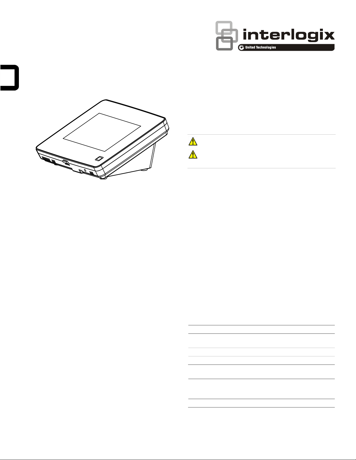
Concord 5” TouchScreen Installation Sheet
Safety information
IMPORTANT SAFETY INFORMATION. READ ENCLOSED
WARNINGS AND SAFETY INFORMATION.
WARNING! Disconnect panel power before servicing.
CAUTION: Use static electricity precautions when
handling electronic components.
Installation guidelines
Description
Concord 5” TouchScreen, model 60-924-3-C4TS5, features a
5-inch color LCD screen with a graphical user interface
designed to control basic functionality of Concord 4, version
4.5 or later.
Multiple touch screens can be added to each Concord panel.
An internal speaker provides system status beeps for trouble
and alarm indications.
The touch screen provides a convenient option for the
following system operations:
• Easily obtain home/building status using At-A-Glance
(AAG) sensor status.
• Arm the system (doors, windows, motion sensors, and
property).
• Disarm the system.
• Activate a panic alarm to call the central monitoring station
in a non-medical emergency.
Equipment
• Alphanumeric keypad (for panel and end user
programming)
• 4-conductor, 18 to 22-gauge wire
• #6 screws and anchors (included)
• Super bus power supply (optional), PN 600-1019
The touch screen can be the primary interface to the panel or it
can act as auxiliary interface working in conjunction with
alphanumeric keypads (such as Interlogix P/N 600-1070-E or
60-983).
• The touch screen is not listed to UL Fire Standards and
may not be programmed for use with a Fire System in
California per CSFM Regulations.
• Mount the touch screen in an environmentally-controlled
area (32°F to 120°F/0°C to 49°C).
• Do not exceed the maximum available power given in the
panel. Refer to the total system power and guideline
section in Concord installation instructions. See Table 1
for touch screen power usage and Table 2 for maximum
wire length between touch screen and panel.
• Depending on system loading, multiple touch screens can
be installed on a Concord 4 system. See the examples in
Table 3 and Table 4.
Table 1: Touch Screen Power Usage
Table 2: Maximum SuperBus Lengths
Tools
• 2.5mm flat-blade screwdriver
• #2 Phillips screwdriver
• Drill and drill bits for opening wallboard (3/16- and 1/2-inch
bits)
© 2018 UTC Fire & Security Americas Corporation, Inc. 1 / 8 P/N 466-5410 (EN) • REV D • ISS 19MAR18
Page 2
Device
Part #
Number
used
Alarm
current
draw
Available
Power
Concord 4
1000 mA
Concord 5”
Touch Screen
60-924-3C4TS5
2
800 mA
ATP 1000
60-983
1
110 mA
Total
90 mA
remaining
Device
Part #
Number
used
Alarm
current
draw
Available
Power
Concord 4
1000 mA
SB2000 voice
only module
60-836
1
600 mA
Concord 5”
Touch Screen
60-924-3C4TS
1
400 mA
0 mA
remaining
SB2000
Power Supply
600-1019
1 2000 mA
ADC LTE
Modem
600-1053LTEAT
1
125 mA
Concord 5”
Touch Screen
60-924-3C4TS5
4
1600 mA
Total
875 mA
remaining
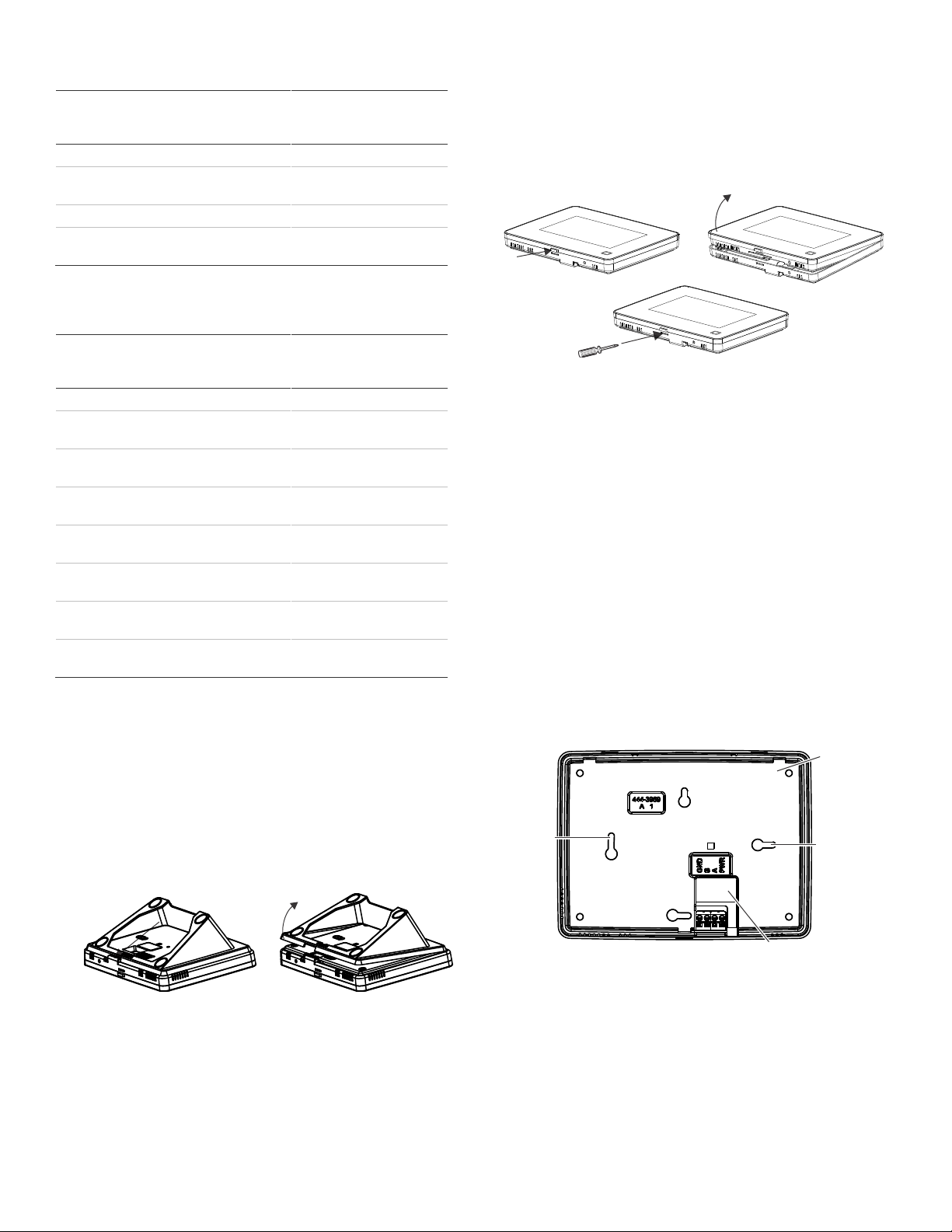
Opening
button
Mounting
hole
Mounting
hole
Mounting
base
Bus wire
drop opening
Table 3: Example – Basic Concord 4 system with two Concord 5”
TouchScreens and one alphanumeric keypad
Table 4: Example - Concord 4 system with four Concord 5”
TouchScreens, one ADC modem, and one panel voice module
(Note: SB 2000 power supply is needed in this configuration)
2. Remove the touch screen from the mounting base
pressing the opening button on the bottom of the touch
screen (as shown in Figure 2). In case the parts stick to
each other, try to separate them by inserting a small
screwdriver into the opening slot beneath the protruding
opening button (Figure 2).
Figure 2: Opening slot
Wall mounting
1. If the unit is to be installed and used on surface utilizing
the desktop stand, skip to step 9.
Wall mounting uses only the mounting base; the desktop
stand is not used.
2. Hold the base on the wall at the desired mounting location
and mark the mounting holes and bus wire drop.
3. At the mounting hole locations, drill 3/16-inch holes into
the wall for plastic anchors.
Preparation
To begin
1. Separate the touch screen and the mounting base from
the preassembled desktop stand. Remove the desktop
stand by holding the touch screen unit with one hand and
prying the desktop stand at the removal tab marking until it
separates (Figure 1) with the other.
Figure 1: Desktop stand removal
4. At the bus wire drop opening, drill a 1/2-inch hole into the
wall.
5. Push the two plastic anchors into the drilled holes and
tighten screws within a quarter-inch of the anchors.
6. Feed the bus wiring through the backside of the bus wire
drop in the mounting base (Figures 3 and 4).
Figure 3: Wire access in mounting base
2 / 8 P/N 466-5410 (EN) • REV D • ISS 19MAR18
Page 3
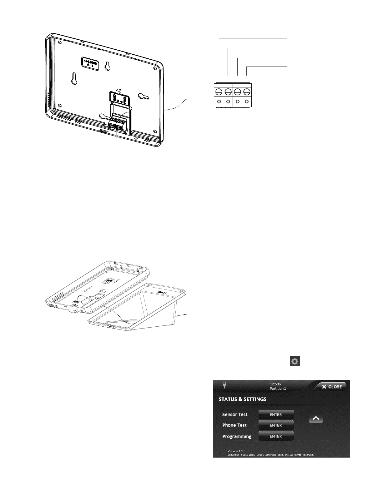
Terminal
Wires
Wires
123
4
+12V (Red)
BUS-A (Green)
BUS-B (White)
GND (Black)
Figure 4: Bus Wire Routing Wall Mount
7. Hang the base using the screws, level the base, and
tighten the screws.
8. Feed any extra bus wire back into wall. Bus wires should
not protrude outside of the bus wire drop opening.
Surface, desktop mounting
If the unit is to be wall mounted, skip to step 11.
9. Feed the bus wiring through the desktop stand from the
backside forward, and then feed the wire through the
backside of the bus wire drop in the mounting base (see
Figure 5).
Figure 5: Bus Wire Routing Surface Desktop Mount
Figure 6: Connecting the touch screen
12. To reattach the touch screen to the mounting base (which
is mounted either to a wall or is attached to the desktop
stand sitting on a surface), angle the top of the touch
screen into the tab hooks on the top of the mounting base
and swing the bottom of the touch screen into the lower
part of the mounting base until you hear an audible click.
Note: If necessary, use a soft cloth to clear smudges on
the touch screen. Do not use glass cleaner.
Power up and bus communication
Follow the steps below for powering up the panel and for
verifying that the TouchScreen and other products like an
alphanumeric keypad are properly communicating with each
other.
Note: On power up, the panel scans the bus for connected
devices, assigns a unit number to each bus device, and
automatically adds the device ID number of each bus device.
1. Verify that all wiring between the panel, touch screen, and
alphanumeric keypad is correct.
2. Connect the panel battery and restore AC power.
The alphanumeric keypad briefly shows SCANNING BUS
DEVICES, then displays date and time.
Note: Emergency button program changes can only be
completed within two minutes of initial power up of touch
screen.
Installer Programming
10. Reattach the desktop stand to the mounting base.
Wiring and final assembly
11. For either mounting, now connect the bus wires to the 4position terminal block (Figure 6).
P/N 466-5410 (EN) • REV D • ISS 19MAR18 3 / 8
The Concord 5” TouchScreen has a keypad emulation mode
that allows installer/dealer code access to panel programming
and configuration.
To access, press the Settings icon on the Main screen and
the Settings screen appears.
Page 4

Press and hold the Enter button for approximately five
seconds. The following screen will appear:
The emulated keypad works and functions the same as the
600-1070-E keypad. To enter programming mode press 8,
followed by a valid installer or master code, 0, 0.
For additional details on programming with the touchscreen,
see Concord 5 in TouchScreen Quick Operation Guide.
To exit programming, press the “Exit “ button or press and hold
the top white bar where info is displayed.
Verifying touch screen bus enrollment and panel
programming touch screen options
Enter programming emulation mode as described above. For
more information on alphanumeric touch pad operation, refer
to the Concord 4 Installation Manual.
1. Go to the Bus Device Programming section in Concord
(System Programming / Security / Accessory Modules /
Bus Devices (shortcut 10,000 for unit ID 0).
The display shows the lowest device address and it’s ID.
This example shows what a device address display may
look like:
UNIT - ID
02110185*
* The 8-digit SuperBus ID number is also located on a
label on the back of the alphanumeric keypad.
2. Cycle through all bus device addresses until the
alphanumeric keypad appears.
3. To program the following touch screen options, choose the
touch screen bus device address.
Change ID
With this menu, change the bus device ID number when
replacing a defective bus device.
To change a device ID:
1. With the display showing the desired bus device, press #,
#.
The display shows DEVICE ID (current ID).
2. Enter the ID of the new bus device.
The display flashes the entered selection. Press # and the
display shows the new setting.
3. Exit programming mode.
4. Remove AC and battery power from the panel.
5. Replace the defective bus device with a new one.
6. Apply AC and battery power to the panel.
Partition assignment
With this menu, assign bus devices to work in the desired
partition.
To assign bus devices to partitions:
1. With the display showing the desired bus device, press #.
2. Press A or B until the display shows DEVICE PTN and
then press #. The display shows PARTITION ASSIGN.
3. Press 1 to 6 to select the desired partition.
The display flashes the entered selection.
4. Press # and the display shows the new setting.
Status beeps
Option not used with touch screen. Touch screen status beeps
can be changed in the touch screen settings menu.
Key beeps
Option not used with touch screen. Touch screen key beeps
can be changed in the touch screen settings menu.
Panel sensor text programming guidelines
Programming for touch screen At-A-Glance (AAG) icons
For best results, do not program sensor names that contain a
combination of the words Door, Window, and/or Motion.
The designator words Door, Window, or Motion should be
programmed within the first three words of the sensor text
sequence. If not, the wrong AAG association may occur.
Door - Sensor names must contain “Door” (item number 50).
When programming a name for a sensor, enter 50 and the
word Door is added to the text. These sensors should be a
sensor group that requires a restoral.
Window - Sensor names must contain “Window” (item number
183). When programming a name for a sensor, enter 183 and
the word Window is added to the text. These sensors should
be a sensor group that requires a restoral.
Motion - Sensor names must contain “Motion” (item number
119). When programming a name for a sensor, enter 119 and
the word Motion is added to the text. These sensors should be
a sensor group that does not require a restoral.
Property - Any sensor that does not contain the words Door,
Window, or Motion. They may be a restoral or non-restoral
sensor.
If a sensor contains the AAG keyword of Door, Window, or
Motion, but the sensor appears in the Property AAG when
tripped, the name of the sensor is too long. The AAG keyword
needs to be moved closer to the start of the sensor name.
4 / 8 P/N 466-5410 (EN) • REV D • ISS 19MAR18
Page 5

LED
System status
Solid blue (while
backlights are on)
Primary power present
Fading blue
Primary power failure
Off
Screen saver active
TouchScreen setting options
Touch the Settings icon on the Home screen and the
Settings screen appears.
Setting options
With the Setting options, adjust the touch screen’s features.
Typical status indicators (excluding light screen):
• Gold - A button is selected.
• Blue - Buttons not selected.
Use the scroll bar to see all of the options (below):
Event History - Touch the Related Show button to view
system events.
Direct Bypass - Touch the Related button to bypass a sensor.
Panel Status - Touch the Related Show button to display the
status of the security system.
Change Partition - Touch the Related button to change
partitions.
Chime - Touch the On or Off button to toggle the touch screen
chime feature on or off. This feature will enable this touch
screen to beep when a certain door opens. Consult the dealer
regarding which doors or windows are programmed to chime
when opened. Refer to the security panel documentation for
information on this feature.
Note: If this device (or any other keypad) is located in areas
that are less secure such as a garage which is not monitored,
be sure Quick Exit is programmed to off.
Emergency Keys (Default on) - Touch the On or Off buttons
to toggle this feature. There will be a prompt to enter a code.
Installer or dealer code must be used. When turned on, the
Emergency button appears. When turned off, the Emergency
button does not appear.
Fire Key (Default off) - Touch the On or Off buttons to toggle
this feature. There will be a prompt to enter a code. Installer or
dealer code must be used.
The fire emergency key will show that the fire key is active. If
the fire emergency option is on, the button
appears under the fire button. If the emergency option is off,
the button does not appear if the button is
pressed.
Note: The Emergency keys and Fire key programming options
appear only within two minutes of initial power up or if the
touch screen is reset.
Status LED
The touch screen has an LED that indicates power and sleep
mode status at a glance. Table 5 explains LED behavior.
Table 5: Status LED
Keypress Volume - Touch the arrow buttons to adjust this
touch screen’s keypress volume level. The siren sounds are
not controlled by this setting.
Beep Volume - Touch the arrow buttons to adjust this touch
screen’s beep volume level. The siren sounds are not
controlled by this setting.
Brightness - Touch the arrow buttons to adjust the brightness
level of this touch screen’s screen.
Default screen - Use this feature to set this touch screen’s
screen saver mode. Select Blank to have the screen and LED
go dark after a period of inactivity. Otherwise, the default will
be the Home screen and the screen will always be lit.
The touch screen will automatically blank daily at 2:00 AM for
60 minutes.
Calibration – The touch screen typically does not need to be
calibrated. However, if the touch screen buttons do not
respond correctly, touch the Show button to access the
Calibration screen. To calibrate the touch screen, touch the +
icons in the corners of the screen using a soft, fine point.
Help - Touch the Help button to access the Help menu, which
displays a list of help topic buttons. Touch the buttons for
information on a given topic.
Set Date/Time - Touch the related button to access the
Date/Time menu.
Code Required Access - Touch the On or Off buttons to
toggle this feature. When turned on, it will require a user
access code to be entered for most touch screen functions.
With code required access, not all icons will be displayed.
Operation
Refer to Concord 5 in TouchScreen User Guide for basic touch
screen operation information.
Refer to the panel documentation for complete Concord 4
programming and operation information.
Emergency button
Touch the button and an Emergency screen
appears. Depending on the system, two or three buttons (the
Panic and Police buttons or the Panic, Police, and Fire
buttons) may appear. Select the appropriate button.
An emergency alarm initiated by mistake can be canceled by
touching the button and entering your user
access code within 30 seconds.
Note: The fire panic cannot be canceled.
P/N 466-5410 (EN) • REV D • ISS 19MAR18 5 / 8
Page 6

Problem
Actions/Solutions
Doesn’t power up (no
display and no beeps
when screen is
pressed)
Check for correct wiring connections at touch
screen and panel terminals.
Make sure panel battery is connected
correctly and panel transformer is plugged in.
Make sure panel transformer is not plugged
in to an electrical outlet controlled by a
switch. Relocate transformer to an
unswitched outlet location if necessary.
Icons not visible
Try touching the touch screen (if screen saver
option is on). Adjust Brightness level. Disable
the screen saver option.
No sound coming from
speakers
Check Status beeps volume and Keypress
volume levels in settings. Check for correct
wiring connections at touch screen and panel
terminals.
Sensors named as
door/window/motion
are displaying under
Property icon
The name of the sensor is too long. Place
door/window/motion earlier in the name or
shorten the name.
Touch screen has red
icon (offline)
This icon is displayed if a touch screen has
incurred some form of communication and/or
hardware failure. Check for correct bus wiring
connections (green and white wires) at touch
screen and panel terminals. If wired correctly
and the failure message persists, the failed
touch screen must be deleted from the touch
screen panel and rescanned. If error
messages continue even after the failed
device has been removed, it is possible that
the failed device is a different touch
screen. In that case, delete all screens from
the Concord and remove them from the
Concord’s bus, and re-scan bus devices.
AAG motion icon
continually shows
sensor is open
Must use non-restoral groups such as motion
group 15 or 17. Using restoral groups may
result in a continuously red AAG motion icon.
Can both door and
motion text be used in
a sensor?
Not recommended.
Degraded or inhibited
touch screen
functionality
Check wiring.
Confirm wire length is not exceeding 120 ft
(22 gauge).
Re-calibrate touch screen.
Problem
Actions/Solutions
Trouble condition not
displayed under status
Refer to event buffer in touch screen and/or
view full status on alphanumeric keypad.
If a Concord 5” TouchScreen has a problem
and the touch screen is reset, the following is
not displayed as part of status:
• Aux low battery
• Aux power trouble
Compatibility
Concord 4 Version 4.5 or later
Power requirements
12 VDC nominal
Current consumption:
Maximum alarm current
400 mA
Typical operation
100 mA
Power saving mode (no
panel AC power)
40 mA
Operating temperature
32 to 120°F (0 to +49°C)
Storage temperature
−4 to +140°F (−20 to +60°C)
Maximum relative humidity
85% noncondensing
Dimensions (L x W x D)
6.7 × 5.0 × 0.8 in. (170 × 127 × 20 mm)
Manufacturer
UTC Fire & Security Americas Corporation, Inc.
2995 Red Hill Ave, Costa Mesa, CA 92626, USA
Warnings and
Disclaimers
THESE PRODUCTS ARE INTENDED FOR SALE
TO AND INSTALLATION BY QUALIFIED
PROFESSIONALS. UTC FIRE & SECURITY
CANNOT PROVIDE ANY ASSURANCE THAT
ANY PERSON OR ENTITY BUYING ITS
PRODUCTS, INCLUDING ANY “AUTHORIZED
DEALER” OR “AUTHORIZED RESELLER”, IS
PROPERLY TRAINED OR EXPERIENCED TO
CORRECTLY INSTALL FIRE AND SECURITY
RELATED PRODUCTS.
For more information on warranty disclaimers and
product safety information, please check
https://firesecurityproducts.com/policy/productwarning/ or scan the QR code.
FCC and Industry
Canada
Compliance
This equipment has been tested and found to
comply with the limits for a Class B digital device,
pursuant to part 15 of the FCC Rules. These limits
are designed to provide reasonable protection
against harmful interference in a residential
installation. This equipment generates uses and
can radiate radio frequency energy and, if not
installed and used in accordance with the
instructions, may cause harmful interference to
radio communications.
However, there is no guarantee that interference
will not occur in a particular installation. If this
equipment does cause harmful interference to
radio or television reception, which can be
determined by turning the equipment off and on,
the user is encouraged to try to correct the
interference by one or more of the following
Testing
Test the touch screen operation by arming/disarming the
system, activating the touch screen panics, and bypassing
sensors to verify correct operation.
Note: Contact the central monitoring station before activating
alarms to avoid dispatching local police and fire departments.
Refer to the panel User Manual for complete system operating
instructions.
Note: Test system at least once per week.
Note: Each control unit shall indicate that the system is
intended to be checked by a qualified technical at least every 3
years.
Troubleshooting
Specifications
6 / 8 P/N 466-5410 (EN) • REV D • ISS 19MAR18
Regulatory Information
Page 7

measures:
- Reorient or relocate the receiving antenna.
- Increase the separation between the equipment
and receiver.
- Connect the equipment into an outlet on a circuit
different from that to which the receiver is
connected.
- Consult the dealer or an experienced radio/TV
technician for help.
This Class B digital apparatus complies with
Canadian ICES-003.
Cet appareil numérique de la classe B est
conforme à la norme NMB-003 du Canada.
Conforms to:
UL 985 Household Fire Warning System Units
UL 1023 Household Burglar-Alarm System Units
UL1610 Central Station Burglar-Alarm Units
(Commercial Burglary)
ULC C1023 Preliminary Standard for Household
Burglar Alarm
ULC S545 Standard For Residential Fire Warning
System Control Units
Warranty Information
MANUFACTURER HEREBY DISCLAIMS ALL WARRANTIES
AND REPRESENTATIONS, WHETHER EXPRESS, IMPLIED,
STATUTORY OR OTHERWISE INCLUDING (BUT NOT
LIMITED TO) ANY WARRANTIES OF MERCHANTABILITY
OR FITNESS FOR A PARTICULAR PURPOSE WITH
RESPECT TO ITS CONCORD 4 PRODUCTS AND RELATED
SOFTWARE. MANUFACTURER FURTHER DISCLAIMS ANY
OTHER IMPLIED WARRANTY UNDER THE UNIFORM
COMPUTER INFORMATION TRANSACTIONS ACT OR
SIMILAR LAW AS ENACTED BY ANY STATE.
(USA only) SOME STATES DO NOT ALLOW THE
EXCLUSION OF IMPLIED WARRANTIES, SO THE ABOVE
EXCLUSION MAY NOT APPLY TO YOU. THIS WARRANTY
GIVES YOU SPECIFIC LEGAL RIGHTS AND YOU MAY
ALSO HAVE OTHER LEGAL RIGHTS THAT VARY FROM
STATE TO STATE.
MANUFACTURER MAKES NO REPRESENTATION,
WARRANTY, COVENANT OR PROMISE THAT ITS
SECURITY PRODUCTS AND/OR RELATED SOFTWARE (I)
WILL NOT BE HACKED, COMPROMISED AND/OR
CIRCUMVENTED; (II) WILL PREVENT, OR PROVIDE
ADEQUATE WARNING OR PROTECTION FROM, BREAKINS, BURGLARY, ROBBERY, FIRE; OR (III) WILL WORK
PROPERLY IN ALL ENVIRONMENTS AND APPLICATIONS.
Contact Information
For general information, see www.interlogix.com. For
customer/technical support, see www.interlogix.com/customersupport or call +1 855 286 8889.
© 2018 UTC Fire & Security Americas Corporation, Inc.
Interlogix is part of UTC Building and Industrial Systems, a unit
of United Technologies Corporation. All rights reserved.
P/N 466-5410 (EN) • REV D • ISS 19MAR18 7 / 8
Page 8

8 / 8 P/N 466-5410 (EN) • REV D • ISS 19MAR18
 Loading...