

Page 1
SuperBus® 2000 Voice Module
Installation Instructions
466-1718 Rev. B
January 2005
Product Summary
The SuperBus® 2000 Voice Module provides voice functions for
Concord
Concord Express
Using an onboard, digital voice chip, the panel announces status
messages through each phone and speaker connected to the
module. In addition, a vocabulary of more than 220 words
provides easy to understand messages.
The voice module provides feedback for single or muliple-partition panels. For multiple partitions, a module can be used for
each partition and connected to a separate speaker.
The module communicates with the panel through the SuperBus
2000
DC supply or an auxiliary 12V DC power supply with backup
battery.
Features
The Voice Module includes the following features:
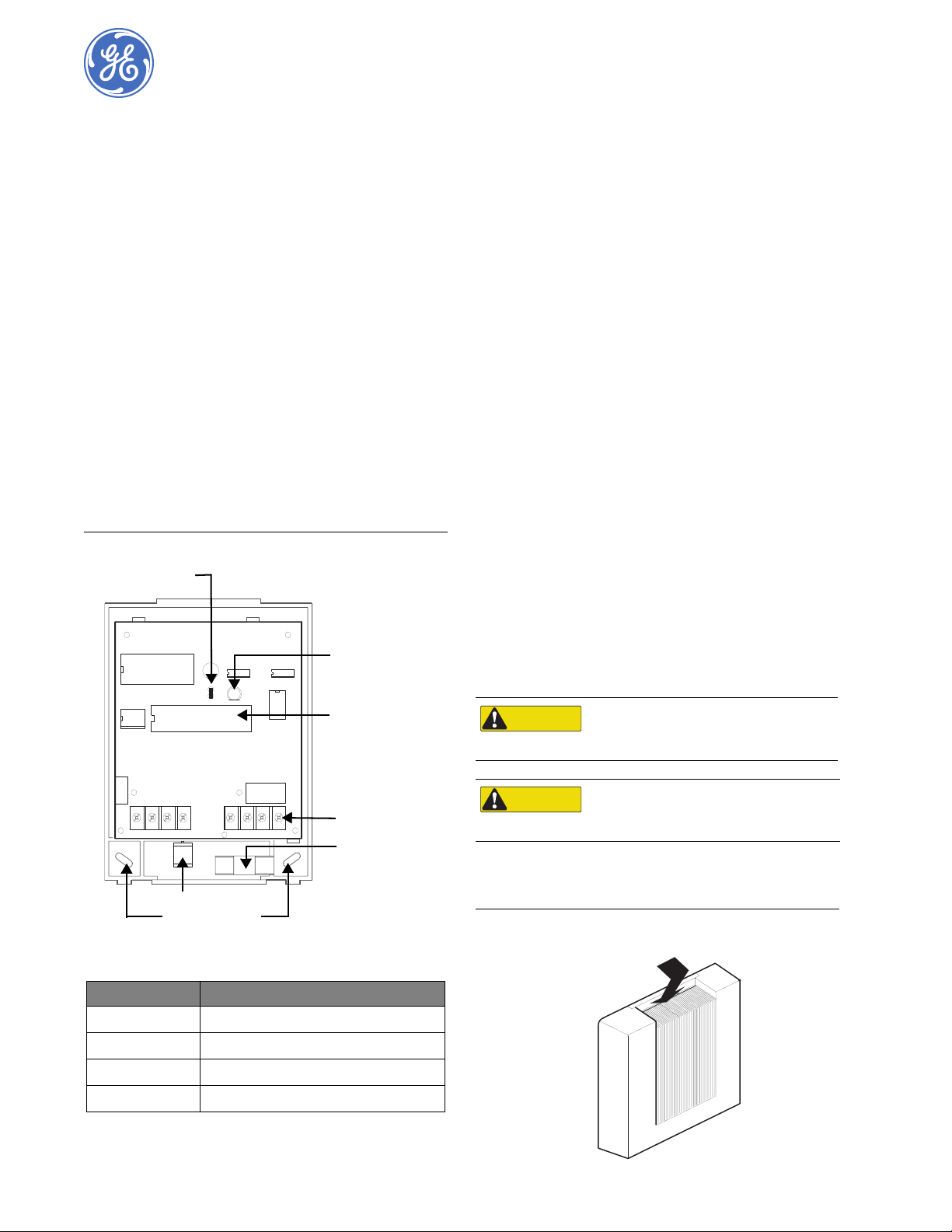
Figure 1. Voice Module Components and Mounting Holes
™
(v2.0-later), Concord 4™, Concord Express™, and
™
(v4) panels.
®
digital databus and may be powered by the panel’s 12V
• User-adjustable, speaker volume control.
• Extensive, 220-plus word vocabulary.
Current Jumper
Status LED
Installation Guidelines
• Use four-conductor, 22-gauge or larger diameter stranded
wire to connect the module to the panel.
• Install the module inside the panel cabinet or as close to the
cabinet as possible.
• For Concord Express systems, leave the current jumper
installed; when installing a Concord (v2.0-later), Concord 4,
or Concord Express (v4) panel, remove the current jumper.
• When the current jumper is installed, the voice module
draws a maximum 300 mA from panel power supply. When
the current jumper is removed, the module draws a
maximum of 600 mA from panel power supply.
• When using panel power to supply bus or hardwired
devices, do not exceed the panel’s total power output. Refer
to specific panel Installation Instructions for further detail.
Tools and Supplies Needed
• Slotted screwdriver
• 3/8”-drive drill and drill bits
• Wire cutter/stripper
• Screws and anchors (included)
• Four-conductor, 22-gauge or larger stranded wire
• Support standoff (included with Concord cabinets)
• 1/4” press-fit reed switch and magnet (not included)
Installation
The module can be mounted...
• On a wall.
• Inside a Concord, Concord 4, Concord Express, or Concord
Express (v4) cabinet.
• Inside a Concord Expansion Enclosure. Refer to specific
cabinet Installation Instructions for procedures.
SuperBus Device
ID Label
J 2
+ 1 2 V
B U S B
B U S A
G N D S P K 1
Magnet Clip
Mounting Holes (3)
Table 1. Module Component Descriptions
Component Function
Device ID Label Identifies a unique device ID number.
Status LED Flashes to indicate normal panel communication.
Wiring Terminals Provides panel and speaker connections.
Current Jumper Reduces current consumption to 300 mA.
S P K 2 A U D 1
A U D 2
Wiring Terminals
Reed Switch
Holder
CAUTION
CAUTION
To prevent damage to the panel or module,
remove the panel’s AC power transformer and
disconnect the backup battery before installation.
You must be free of static electricity when
handling electronic components. Touch a bare
metal surface before touching the circuit board.
Mounting the Module on a Wall
1. Remove the module cover (see Figure 2).
Figure 2. Removing the Module Cover
Press down and
pull away from base
Page 2
2
SuperBus® 2000 Voice Module
Installation Instructions
2. Place the backplate on the wall and mark the three mounting
holes (see Figure 1).
3. Drill for the mounting holes and insert appropriate anchors.
4. Secure the backplate to the wall with the included screws.
Mounting a Module in a Concord, Concord 4, or
Concord Express (v4) Panel
1. Remove the panel’s AC power transformer and disconnect
the backup battery.
2. Remove and discard the module cover (see Figure 2).
3. Insert support standoffs on to the panel circuit board (see
Figure 3).
Figure 3. Support Standoff
Panel End
Module End
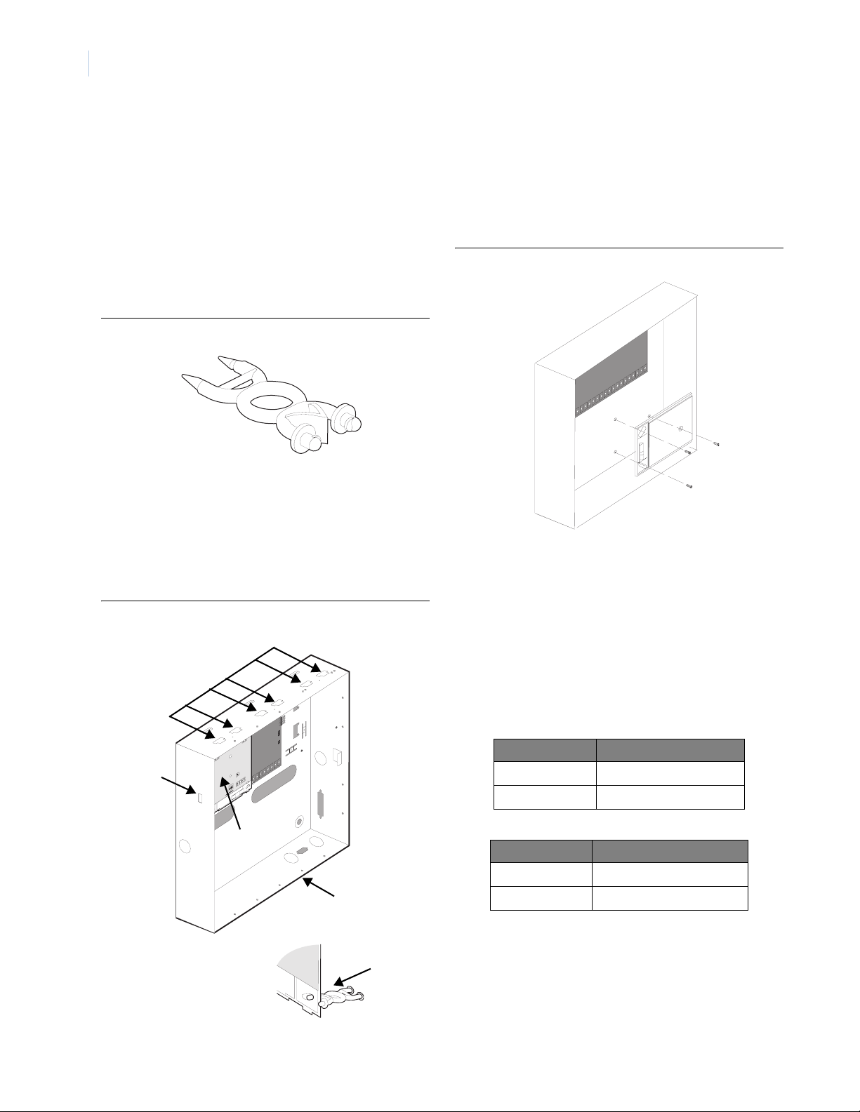
4. Slide the module backplate on to the clips located in the
cabinet’s center or top-left corner (see Figure 4).
Note: The mounting clips in the top-right corner of the cabinet
are designed for a receiver module. If a receiver module is
not in use, the mounting clips may be used for the voice
module.
5. Push the lower-right corner of the module on to the support
standoff (see Figure 4).
Figure 4. Mounting the Module in a Concord, Concord 4, or Concord Express (v4) Cabinet
Mounting Clips (6)
Mounting the Module in a Concord Express Panel
1. Remove the panel’s AC power transformer and disconnect
the backup battery.
2. Remove and discard the module cover (see Figure 2).
3. Position the module over the cabinet mounting holes so the
terminals are to the left (see Figure 5).
4. Secure the module to the cabinet with the mounting screws.
Figure 5. Mounting the Module in a Concord Express Cabinet
Wiring
Wiring the Voice Module includes the following:
• Running required wires for power, bus, and speaker
communications.
• Connecting module wires for use in a Concord system.
For power and bus connections, route a four-conductor, 22-gauge
or larger diameter stranded wire from the module to the panel
(see Table 2 for wire length limits). Route a two-conductor, 22gauge or larger stranded wire cable from the module to the
speaker.
Side Tab
Mounted Module
Panel Cabinet
Support
Standoff
Table 2. Maximum Bus and Power Wire Lengths
Wire Gauge Maximum Length
18 120 feet
22 40 feet
Table 3. Maximum Speaker Wire Lengths
Wire Gauge Maximum Length
18 440 feet
22 175 feet
Page 3

3
Wiring Connections for Concord, Concord 4, and
Concord Express (v4) Panels
Figure 6. Wiring Module and Speaker - Concord, Concord 4, or Concord Express (v4) Panels
Concord Module Wiring Connections
Module Terminals
B U S
+ 1 2 V
A
1 2
4 5
3
G N D + 1 2 V
Panel Terminals
B U S
B
3 4
B U S
A
Hardwire Interior
Speaker (60-528)
S P K 1
G N D
6
B
S P K 2 A U D 1
5 6
Not Used
7 8
7
* for Partition 1 Only
Wiring Connections for Concord Express Panels
Figure 7. Wiring Module and Speaker in a Concord Express Panel
Concord Express Module Wiring Connections
Hardwire Interior
Speaker (60-528)
Not Used
A U D 2
Once programmed, if someone opens the module cover, the
tamper switch opens and causes an alarm.
The reed switch holder and magnet clip are located on the bottom
of the backplate (see Figure 1).
1. On the module’s backplate, place the reed switch into the
reed switch holder.
2. Remove the magnet clip from the module backplate and
insert the magnet into the tabs on the module cover. Next,
press the magnet clip over the magnet until the clip locks
into place (see Figure 8).
3. Connect the normally closed reed switch (in series with a 2k
Ohm EOL resistor) to any zone input and zone common
terminal (see Figure 8). The resistor should be located
inside the module cover at the reed switch.
Figure 8. Installing the Reed Switch
8
To Input
Zone
Module Backplate
Magnet Clip
Reed Switch
2k Ohm EOL Resistor
(49-467)
Module Cover
Magnet
Power Up and Bus Communication
Module Terminals
+ 1 2 V
1 2 3 4 5 6 7 8
3
G N D + 1 2 V
Panel Terminals
B U S
B U S
B S P K 1
A
4 5
G N D
6
B
B U S
A
S P K 2 A U D 1
A U D 2
Installing a Cover Tamper Switch
If you do not mount the module inside a cabinet, it is recommended that you add a cover tamper switch.
To mount a tamper switch, first install a UL listed 1/4-inch pressfit reed switch on the module backplate. Next, wire the switch to
any unused panel, module, or SnapCard™ zone input terminal.
For Concord, Concord 4, and Concord Express (v4)
Panels
Note: To enter the panel’s program mode and verify unit
numbers, an alphanumeric touchpad must be connected
to all Concord panels.
When powering the system and verifying bus communication,
follow the procedures listed below.
1. Verify that panel, touchpad, and module wiring is correct.
2. Connect the panel’s backup battery and plug in the AC
power transformer. An alphanumeric touchpad display
appears.
3. Verify the module’s status LED flashes.
4. If desired, enter the panel’s program mode to verify if a
device ID exists (see panel specific panel Installation
Instructions for further detail).
Note: If the status LED does not flash, unplug the panel’s AC
power transformer and disconnect the backup battery.
Replacing Module Cover/Closing Cabinet
• If the Voice Module is mounted on a wall, replace the cover.
• If the Voice Module is mounted in a cabinet, close the
cabinet door.
Page 4

4
SuperBus® 2000 Voice Module
Installation Instructions
Testing and Troubleshooting
If the module’s status LED remains off:
1. Enter the panel’s program mode to verify the panel recognizes the module (see specific panel Installation Instruc-
tions).
2. Inspect for proper wire connections.
3. Ensure the panel’s AC power transformer is plugged in and
the backup battery is connected.
4. If the status LED remains off, replace the module.
Specifications
Compatibility Concord, Concord 4, Concord Express, and
Power Requirements 12V DC nominal; 600 mA maximum; 300 mA
Operating temperature 32° to 120°F (0° to 49°C)
Storage temperature 30° to 140°F (-34° to 60°C)
Max. relative humidity 90%, non-condensing
Dimensions 5.25” x 4.125” x 1.0” (L x W x D)
UL Listings (Ancillary use only) UL 985 Household Fire Warning System Units
Concord Express (v4) panels.
with Jumper installed.
UL 1023 Household Burglar Alarm System
Units
Notices
FCC Part 15 Information to the User
Changes or modifications not expressly approved by GE Security can
void the user’s authority to operate the equipment.
FCC Part 15 Class B
This equipment has been tested and found to comply with the limits for a
Class B digital device, pursuant to Part 15 of the FCC Rules. These limits
are designed to provide reasonable protection against interference in a
residential installation.
This equipment generates, uses, and can radiate radio frequency energy,
and, if not installed and used in accordance with the instructions, may
cause harmful interference to radio communications. However, there is
no guarantee that interference will not occur in a particular installation.
If this equipment does not cause harmful interference to radio or television reception (which can be determined by turning the equipment off
and on), the user is encouraged to correct the interference by one or more
of the followig measures:
• Reorient or relocate the receiving antenna.
• Increase the separation between the equipment and receiver.
• Connect the affected equipment and the panel receiver to separate
outlets on different branch circuits.
• Consult a dealer or experienced radio/TV technician for help.
GE Security
1275 Red Fox Road
Arden Hills, MN 55112
www.gesecurity.com
Technical Support
T: 800.777.2624
F: 651.779.4890
 Loading...