

Page 1
6XSHU%XV56
$XWRPDWLRQ0RGXOH
ITI Part No. 60-783-02
Document Number: 466-1876 Rev. A
February 2001
Product Summary
The ITI SuperBus 20 00 RS-2 32 Autom ation Modu le allows
you to connect a compatible third-party automation device
to any compatible system panel.
For additional security, a magn etic switch can be added and
connected to the built-in input zone to provide module
tamper protection.
Power for the module is provide by the system panel.
Features
❑ RS-232 automation por t .
❑ Supervised, fire-rated zone input.
❑ On-board status indication.
❑ SuperBus 2000 automatic addressing data bus.
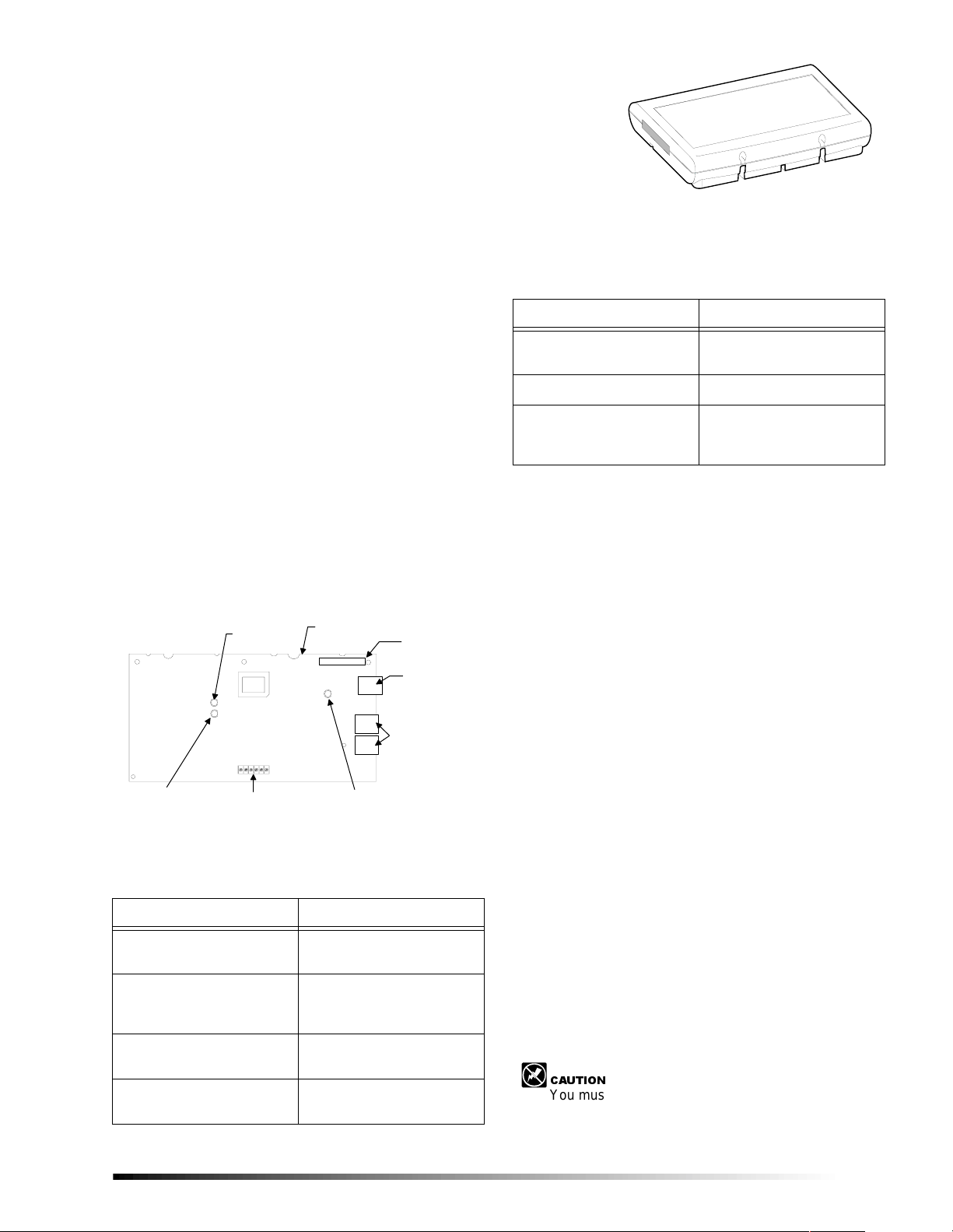
Figure 1 shows the main module components and Table 1
describes them
B U S
S T A T U S L E D
M O D U L E
P O W E R L E D
Figure 1. Module Circuit Board Components
W I R I N G T E R M I N A L S
C I R C U I T C A R D
I D : X X X X X X X X
R S - 2 3 2 L E D
Table 1. Module Component Descriptions
8 8 4 5 g 0 3 c . d s f
U N I Q U E
S U P E R B U S 2 0 0 0
I D N U M B E R L A B E L
R S - 2 3 2 S E R I A L
C O N N E C T O R
P H A S T
C O N N E C T O R S
( 2 ) ( U N U S E D )
8845G02A.DSF
Installation Instructions
Table 1. Module Component Descriptions
Component Function
RS-232 Connector Provides connection to
automation device.
PHAST Connectors Not used.
Wiring Terminals Used for panel SuperBus
and module zone input
connections.
Installation Guidelines
❑ Do not exceed the panel total auxiliary output power
when using panel power for bus devices and hardwired
sensors that require panel power ( see the specif ic pane l
Installati on Instructio ns).
❑ Maximum current draw of the module (from the panel)
is 35mA.
❑ Use 4-conductor, 22-gauge or larger wire from the
module to the panel.
Tools and Supplies Needed
❑ Small blade and Phillips screwdrivers
❑ Drill and bits for screws and/or anchors
❑ Case tamper switch and magnet (optional)
❑ 9 pin RS-232 serial cable
Accessory kit includes:
❑ 3/8-inch self-tapping screws
❑ #6 panhead screws
❑ 2K Ohm EOL resistor (49-467)
❑ Wall anchors
Component Function
Power LED Indicates mo dule power
status.
Bus Status LED Flashes to indicate normal
communication to the panel
bus.
RS-232 Status LED Indicates RS-232
transmission or reception.
Unique ID number Label Indicates mo dule unique
identification number.
Installation
The module can be mounted on any i n ter i or wal l (protected
from the elements).
Installing the Module
The module should be mounted no more than 25 feet from
the automation device in the same room.
&$87,21
You must be free of static electricity before handling
circuit boards. Wear a groun ding st rap or t ouch a ba re
metal surface to discharge static electricity.
1
Page 2
Panel Wiring
8845G1A.DSF
COVER SCREWS (2)
BACKPLATE
CIRCUIT CARD
COVER
CARD LATCHES (2)
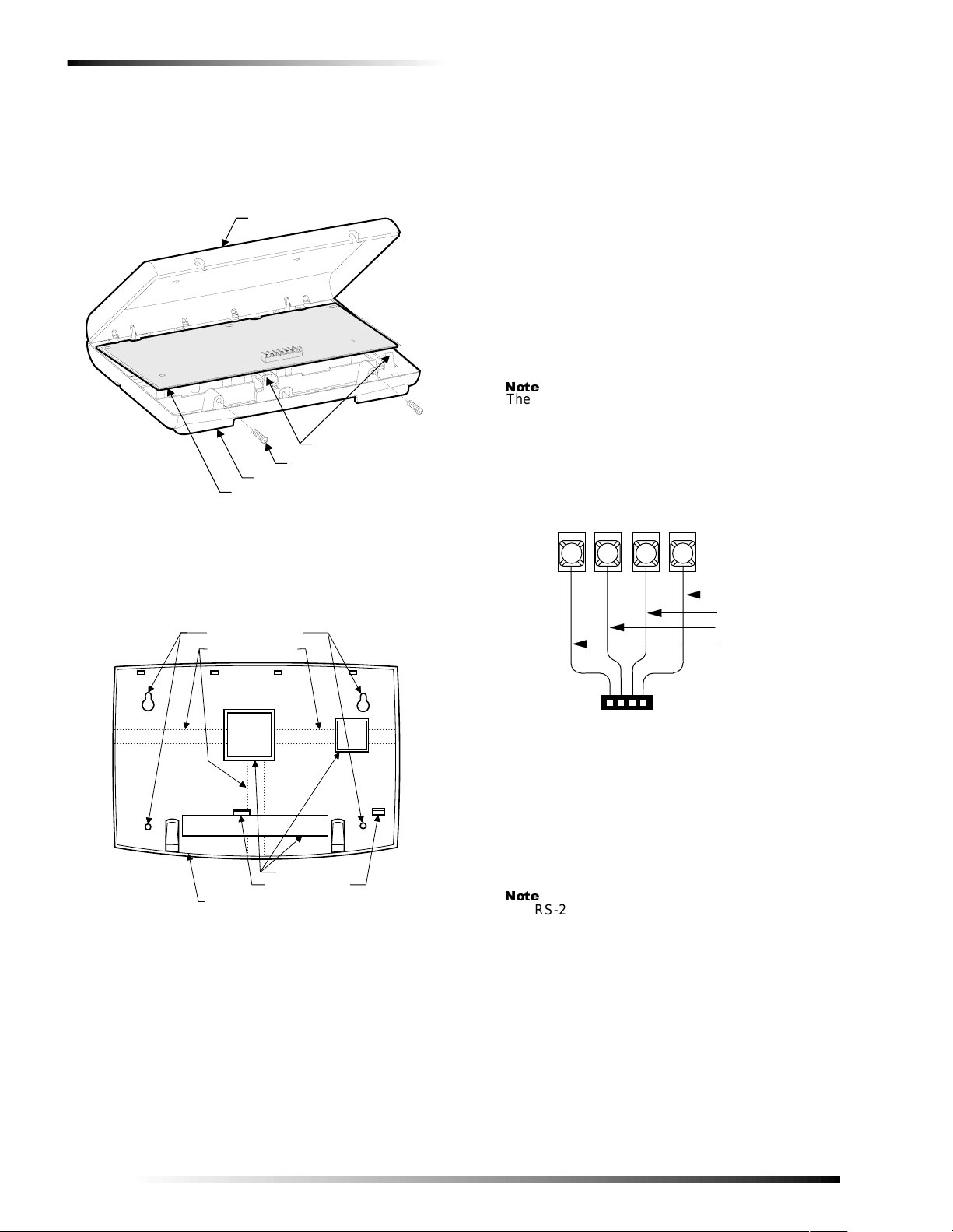
To mount the module on a wall:
1. Turn off panel power and disconnect backup battery(s).
2. Remove the module cover and circu it card and s et them aside (Figure 2).
Figure 2. Removing Plastic Case Cover and Circuit
Card
3. Place the module backplate on the wall and mark the mounting holes locations (Figure 3).
MOUNTING HOLES (4)
WIRE CHANNELS (3)
to Figure 5 and T ab le 2 for wiring exampl es and connection
descriptions.
To wire the module to the panel:
1. Make sure power is turned off to the panel.
2. Make sure the power transformer and backup bat tery(s) are disconnected from the panel.
To wire the module to the Advent panel:
1. Wire the module to the panel SuperBus Wiring harness
as shown in Figure 4. (Refer to panel Installation
Instructions for cable types and maximum cable
lengths.)
2. Plug the wiring harness i nto one of the panel SuperB us Connectors.
1RWH
The RS-232 Automation Module is compatible with
Advent panels using software version 1.6 or later.
S U P E R B U S R S - 2 3 2
A U T O M A T I O N M O D U L E
T E R M I N A L S T R I P
+ 1 2
V D C
B U S
B U S
A
2
1
G N D
B
4
3
B L A C K ( G N D )
W H I T E ( B U S B )
G R E E N ( B U S A )
R E D ( + 1 2 V D C )
WIRE ACCESS (3)
CARD LATCHES (2)
ENCLOSURE BACKPLATE
(COVER AND CARD REMOVED)
Figure 3. Plastic Case Mounting Holes
8845G08A.DSF
4. Drill the holes and insert the appropriate anchors.
5. Secure the back plate to the wall with panhead screws.
6. Snap the circuit card back into the back plate.
Panel Wiring
This section describes how to wire the module to the panel
and how to connect hardwire sensors to the module. Refer
2
A D V E N T P A N E L S U P E R B U S
W I R I N G H A R N E S S 4 9 - 4 6 2
Figure 4. Advent Panel SuperBus Wiring
8 5 4 3 1 1 0 B . D S F
To connect a device to the module:
1. Attach the appropriate DB-9 serial cable to the connector on the module (Figure 5). This cable must be less
than 25 feet in length.
1RWH
The RS-232 Automation Module’s RS-232 port is configured as a DCE device. Therefore it transmits data
on pin 2, receives data on pin 3. Pin 5 is the signal
ground. All other pins are not used.
If the automation device’s RS-232 port is configured
as a DTE port, then a “straight through” DB-9 cable
must be used. Otherwise a “null modem” cable must
be used.
Refer to the automation device instructions for information about its RS-232 port.
2. If necessary set the communication parameters on the
automation device’s RS-232 port as follows: 8 data
bits, 9600 bps, odd parity, 1 stop bit.
3. Connect an input device (if used) to the module zone input terminals (Figure 5)
Page 3

Installing a Case Tamper Switch
Installi ng a Case Tamper Switch
If the module is visible, you may want to add case tamper
detection. Then, if someone opens the cover, the switch
opens and causes an alarm. To add module case tampering,
install a magnet in the cover and a reed s witch into the back
plate or case. Wire the switch to the module or one of the
panel zone inputs. (See Figure 5 or pa nel Installation
Instructions).
Power Up and Bus Communication
This section describes how to power up the panel and the
module and get them communicating with each other.
To power up th e p anel and the module:
1. Verify that all wiring at the panel and the module are correct.
2. Reconnect the panel batteries and plug in the power
transformer. The module power LED should be on.
3. On initial power up, the panel automatically adds
(learns) the module into panel memory.
After a few seconds, the module bus status LED should
flash at a rapid and random rate to indicate it is learned
into the panel.
If the module bus status LED flashes at a steady rate,
the module must be manually added (learned) into
panel memory. (Refer to the panel Installation Instruc-
tions for adding SuperBus modules.)
Programming/Operating the Module
Refer to the panel Installation Instructions for module
input/output programming and operation.
A U T O M A T I O N M O D U L E
C I R C U I T B O A R D
D B - 9 S E R I A L C A B L E
T O P A N E L
S U P E R B U S
T E R M I N A L S O R
W I R I N G H A R N E S S
( S E E O T H E R
F I G U R E O R T A B L E )
C L O S E D ( N / C )
8 8 4 5 g 0 5 b . d s f
U L - L I S T E D
N O R M A L L Y
C O N T A C T S
I N S E R I E S
A U T O M A T I O N
D E V I C E
1 2 3 4 5 6
+ 1 2 V D C
B U S A
B U S B
G N D
Z C O MZ O N E 1
< O R >
U L - L I S T E D
N O R M A L L Y
O P E N ( N / O )
C O N T A C T S
I N P A R A L L E L
2 . 0 K O h m E O L R E S I S T O R 4 9 - 4 6 7
( I N S T A L L A T L A S T C O N T A C T )
Figure 5.Panel/Module Wiring
3
Page 4

Module Wiring Terminal Connections
Module Wiring Terminal
Connections
Table 2. SuperBus 2000 Automation Module Terminal Connections
Terminal Name Used For
1 +12V DC SuperBus DC power supply input. 12 VDC @35 mA maximum draw from panel.
3 BUS A SuperBus communication connection.
4 BUS B SuperBus communication connection.
5 GND SuperBus common ground connection.
6 ZONE 1 Zone 1 input connection.
7 ZCOM Zone input common connection.
Testing
Verify proper operation of the automation device. Refer to
the automation device instructions for an explanation of
proper operation.
Troubleshooting
Module POWER LED stays off.
1. Check module and panel power.
2. Check SuperBus wiring and connections
Module BUS STATUS LED stays off.
1. Check SuperBus wiring and connections
2. Check for proper panel/SuperBus module programming and initialization.
Module BUS STATUS LED stays on.
1. Re initialize panel and module by turning panel power off and on.
2. Module circuit failure. Replace the module.
Module BUS STATUS LED blinks, but no automation
device operation.
1. Check that the automation device power is on.
2. If the LED is not blinking at a rapid, random rate, the module is not learned into the panel.
3. Check module and device cables and connections.
4. Check panel/module programming.
5. Check the RS-232 LED. It should blink at least once every 4 seconds.
Specifications
Compatibility: Advent (and Custom Versions)
security panels. (Software version
1.6 or later)
Power Requirements: 12 VDC nominal, 35 mA maxi-
mum draw from panel.
Panel Data Bus: ITI SuperBus auto addressing digi-
tal data bus.
Automation Port: RS-232, DCE
Zone Input: One supervised, fire-rated zone.
Storage Temperature: -30° to 140° F (-34° to 60° C)
Operating Temperature: 32° to 140° F (0° to 60° C)
Maximum Humidity: 95% relative humidity, noncon-
densing.
Approvals/Listings: FCC Part 15
Dimensions: 6.0” x 8.5” x 1.5” (L x W x D).
Case Material: High-Impact, ABS plastic.
Case Color: Belgian gra y.
Installation: Wall Mount
4
Page 5

Notices
FCC Part 15 Information to the User
Changes or modifications not expressly approved by Interlogix, Inc. can
void the user’s authority to operate the equi pment.
FCC Part 15 Class A
This equipment has been tested and found to comply with the limits for
a class A digital device, pursuant to pa rt 15 of the FCC rule s. Th ese
limits are designed to provide rea s ona ble protection against harmf ul
interferen ce when the equ ipment is operated in a commercial envir o nment.
This equipment generates, uses, and can radiate radio frequency energy
and, if not installed and used in accordance with the instruction manual,
may cause harmfu l interference to r adio communications. Operation of
this equipment in a residential area is likely to cause harmful interference in which case users wi ll be required to correct the interference at
their own expense.
FCC Part 15 Class B
This equipment has been tested and found to comply with the limits for
a Class B digital device, pursuant to pa rt 15 of th e FCC Rules. These
limits are designed to provide reasonable protection against interference
in a residential installation.
Notices
This equipment generates, uses, and can radiate radio frequency energy
and, if not installed and used in acc ordance with the instructions , m ay
cause harmful interference to radio communications. However, there is
no guarantee th at interference will not occur in a particular in stallation.
If this equip ment does caus e h armful inter ference to radio or television
reception, which can be det erm i ned by turning the equipment off and
on, the user is encouraged to try to correct the interfe rence by one or
more of the following measures:
❑ Reorient or relocate the receiving antenna.
❑ Increase the separation betw een the equipment and rece ive r.
❑ Connect the affected equipment and the panel receiver to separate
outlets, on different branch circ ui ts.
❑ Consult the dealer or an experienced radio/TV technician for help.
5
Page 6

Notices
ITI | 2266 SECOND STREET NORTH | NORTH SAINT PAUL MN | 800-777-2624 | www.interlogixinc.com
©2001 Interlogix,™ Inc. Interlogix and Concord are trademarks of Interlogix, Inc. ITI, Advent, and SuperBus are registered trademarks of Interlogix, Inc.
6
 Loading...