

Page 1
Voice Siren 25/70 Volt Converter Card
Installation Instructions
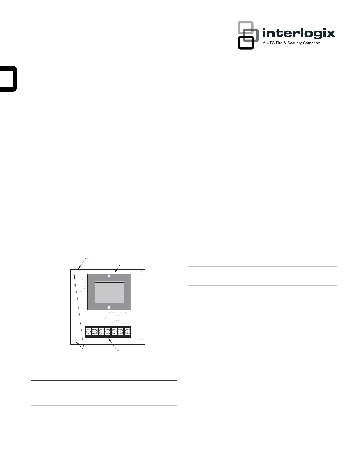
Terminal strip Used for panel and voice siren connections.
Product summary
The Voice Siren 25/70 Volt Converter Card adds high voltage
voice siren audio output capability to Advent panels.
Note: The converter card is only for use with the tone
generator output. It is not listed for use in voice evacuation.
The card mounts inside the panel enclosure and is powered by
the panel voice siren output. The card converts the panel 4ohm voice supervised siren output to a 25 or 70 volt, 24 watt
supervised output. All circuits associated with this card are
power limited.
Card components
Figure 1: Card components
VOICE SIREN
25/70 VOLT
CONVERTER CARD
60-773
TRANSFORMER
Installation Guidelines
• Advent systems support one card per panel.
• Do not exceed the panel voice siren output power (see
panel Installation Instructions).
Note: The Voice Siren Converter Card must have a
minimum load of 1 watt and a maximum of 24 watts.
Tools and Supplies Needed
• Small and medium blade screwdrivers.
• #6x1/4 -inch self-tapping phillips pan head screws
(included).
• 2K ohm 5 watt end-of-line (EOL) resistor assembly (49-
482) (included with card).
• 14-gauge or larger solid wire. Use larger gauge wire for
long wire runs.
Caution: Do not use the 3 watt end-of-line resistors that are
included with Advent panels.
Installation
The card is mounted inside the panel enclosure.
Caution: To prevent damaging the panel or card, remove
panel AC power and disconnect the backup battery before
MOUNTING HOLES (4)
Table 1: Card components descriptions
Component Function
Mounting holes Holes match mounting screw locations in panel
enclosure.
Transformer Converts the panel voice siren output to 25/70 Volt
output.
P/N 466-1566 • REV F • 07APR11 1
WIRING TERMINAL
STRIP
installation.
You must be free of static electricity when handling electronic
components. Wear a grounding strap or touch a bare metal
surface before handling circuit boards.
Mounting the Card
1. Remove panel AC power and disconnect the panel
backup battery.
Page 2
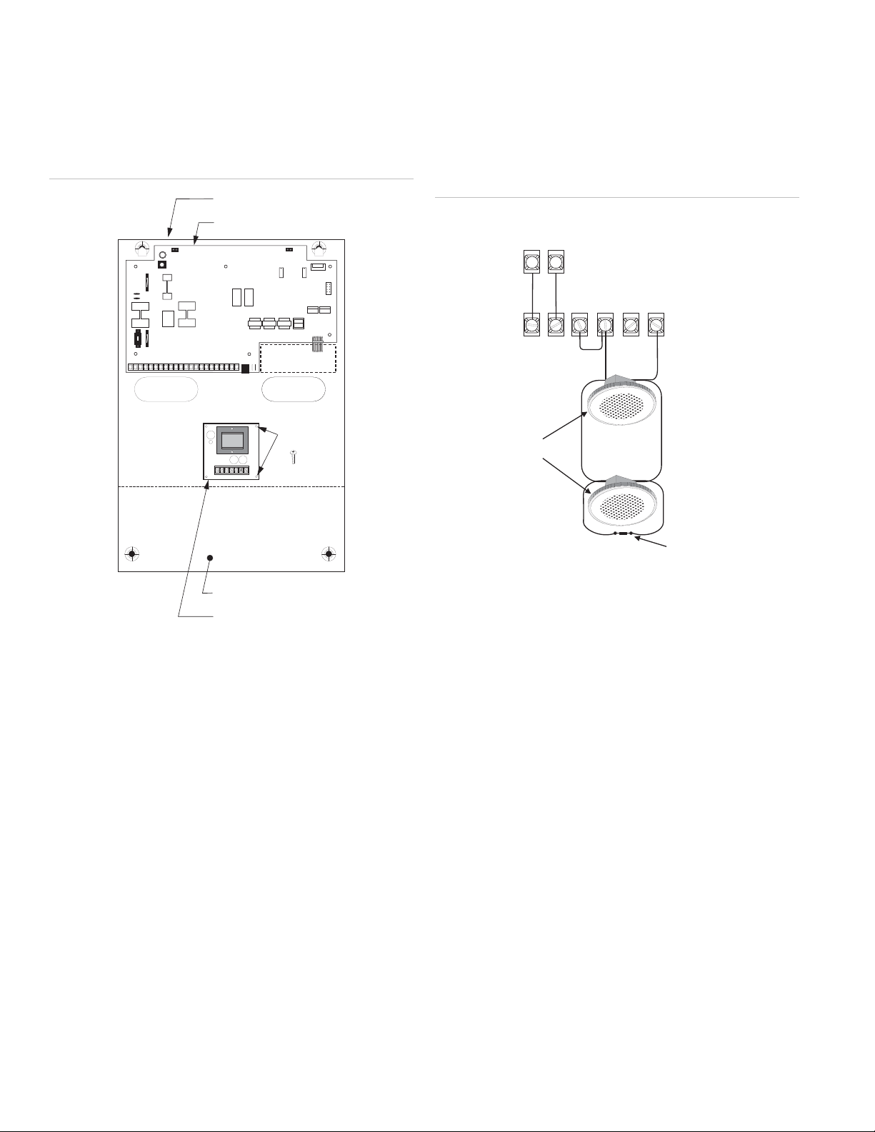
2. Place the card inside the cabinet below the panel circuit
g
board (Figure 2 below).
Secure the card to the cabinet mounting standoffs with
3.
#6x1/4 -inch self-tapping phillips pan head screws.
Figure 2: Mounting the card in the Advent panel
PANEL ENCLOSURE
PANEL CIRCUIT BOARD
+
-
TERMINAL STRIP
OPTIONAL
EXPANSION CARD
ALIGN CARD
HOLES WITH
STANDOFFS
(4)
2. Wire the card to the panel and voice sirens as shown in
Figure 3 below.
Note: 70 volt
wiring and supervision is shown. For 25 volt
wiring, connect speakers to terminals Common and 25V
and jumper + Supervision to 25V terminal.
Figure 3: Typical Advent panel card wiring
PANEL
TERMINALS
VOICE
VOICE
SIREN
SIREN
9
10
VOICE SIREN CONVERTER
CARD TERMINALS
-
+
4 OHMS
L-LISTED SPEAKERS
(PARALLEL)
+
SUPER-
VISION
COM-
MON
25V70V
BACKUP BATTERY(S) AREA
VOICE SIREN 25/70 VOLT
CONVERTER CARD OPTION
Wiring the Card
This section describes how to wire the card to an Advent panel
and speakers.
Note : (A) Class 2, Class 3, and power-limited fire alarm
circuits must be installed using FPL, FPLR, FPLP, or substitute
cable permitted by the National Electrical Code ANSI/NFPA
70. Wire that extends beyond the cable jacket must be
separated from all other conductors by a minimum of 1/4-inch
or by a nonconductive barrier.
Or
(B) Class 2, Class 3, and power-limited fire alarm circuit
conductors must be installed as Class 1 or higher circuits.
2K OHM 5 WATT
EOL RESISTOR
ASSEMBLY 49-482
(LOCATE AT
LAST DEVICE)
Note: Separate in and out conductors must be used at each
speaker. Do not loop a single wire around each terminal.
Powering Up the Panel
This section describes how to power up the panel and the
card.
To power up the panel and card:
1. Verify that all wiring at the panel and the card is correct.
2. Reconnect the panel battery and restore panel AC power.
Testing
Refer to the specific panel’s Installation Instructions for testing
voice siren operation and supervision.
To wire the card:
1. If you have not already done so, remove panel AC power
and disconnect the panel backup battery.
2 Voice Siren 25/70 Volt Converter Card Installation Instructions
Page 3

Specifications
Compatibility Advent panel (60-562-03)
Power requirements Advent panel voice siren output.
Operating temperature 32° to 120° F (0° to 49° C).
Storage temperature -30° to 140° F (-34° to 60° C).
Maximum humidity 90% relative humidity, non-condensing.
Inputs One 4-ohm. 25 watt supervised audio input.
Outputs One power-limited 25 volt or 70 volt, 24 watt
maximum, supervised audio output.
Dimensions 3.2" x 3.2" x 1.5" (LxWxD).
Installation Panel enclosure mounting.
protection against harmful interference when the equipment is
operated in a commercial environment.
This equipment generates, uses, and can radiate radio
frequency energy and, if not installed and used in accordance
with the instruction manual, may cause harmful interference to
radio communications. Operation of this equipment in a
residential area is likely to cause harmful interference in which
case users will be required to correct the interference at their
own expense.
FCC Part 15 Class B
his equipment has been tested and found to comply with the
T
limits for a Class B digital device, pursuant to part 15 of the
FCC Rules. These limits are designed to provide reasonable
protection against interference in a residential installation.
Regulatory information
Manufacturer UTC Fire & Security Americas Corporation, Inc.
1275 Red Fox Rd., Arden Hills, MN 55112-6943,
USA
Listings FCC Part 15
UL 864: Control Units for Fire-Protective
Signaling Systems
UL 1711: Fire Protective Signaling Systems
ULC Canada Commercial Fire/Burglary Warning
System (applied for)
CSFM California State Fire Marshall (applied for)
DOD Sensitive Compartment Information Fac.
(applied for)
FM Factory Mutual (applied for)
MEA New York City Material Equipment
Acceptance (applied for)
Note: See specific panel installation instructions
for complete UL installation requirements for the
system you are installing.
Notices
This equipment generates, uses, and can radiate radio
frequency energy and, if not installed and used in accordance
with the instructions, may cause harmful interference to radio
communications. However, there is no guarantee that
interference will not occur in a particular installation.
If this equipment does cause harmful interference to radio or
television reception, which can be determined by turning the
equipment off and on, the user is encouraged to try to correct
the interference by one or more of the following measures:
• Reorient or relocate the receiving antenna.
• Increase the separation between the equ ipment and
receiver.
• Connect the affected equipment and the panel receiver to
separate outlets, on different branch circuits.
• Consult the dealer or an experienced radio/TV technician
for help.
Contact information
www.utcfireandsecurity.com or www.interlogix.com
For customer support, see www.interlogix.com/customer-
support
Copyright © 2011 UTC Fire & Security. All rights reserved.
FCC Part 15 Information to the User
Advent is a registered trademark of UTC Fire & Security.
Changes or modifications not expressly approved by UTC Fire
& Security can void the user’s authority to operate the
equipment.
FCC Part 15 Class A
his equipment has been tested and found to comply with the
T
limits for a class A digital device, pursuant to part 15 of the
FCC rules. These limits are designed to provide reasonable
Voice Siren 25/70 Volt Converter Card Installation Instructions 3
 Loading...