

Page 1
4 Output Expansion
CAUTION
CAUTION
MOUNTING
SCREW
HOLES (2)
8543117A.DSF
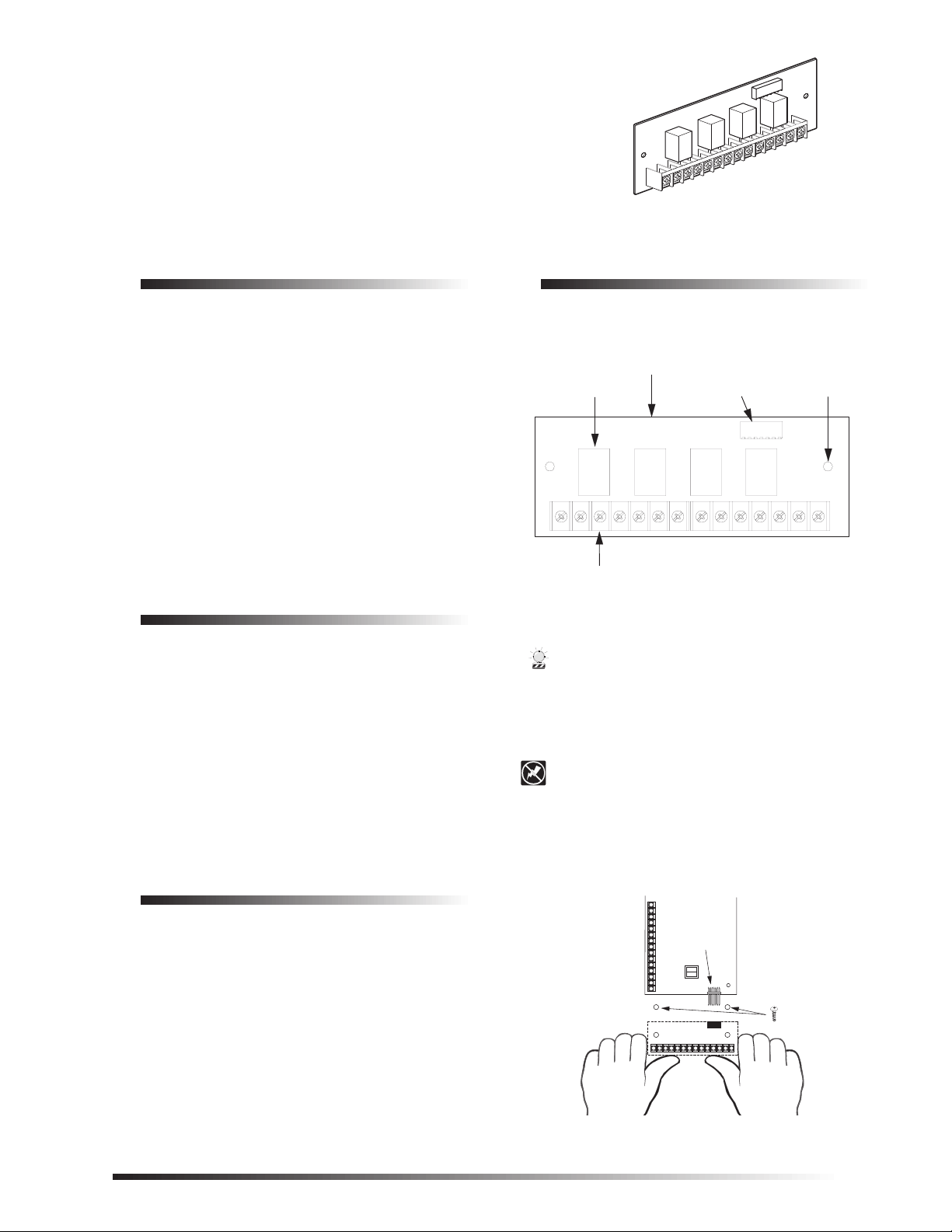
RELAYS (4)
WIRING
TERMINALS
PANEL
CONNECTOR
4 RELAY OUTPUT
EXPANSION SNAPCARD
OPTIONAL
EXPANSION CARD
CONNECTOR
OPTIONAL
EXPANSION CARD
CONTROL PANEL
CIRCUIT BOARD
(2)
ALIGN BOARD
HOLES WITH
STANDOFFS
SnapCard
ITI Part No. 60-758
Document Number: 466-1366 Rev. C
November 2000
Product Summary
The Four Output Expansion SnapCard™ lets you control
devices by adding hardwire outputs to a Concord, Concord
Express, or Advent panel.
This card can be installed into the Concord and Concord
Express expansion connector. On Advent panels this card
can be installed into the primary or secondary expansion
connector and in combination with other expansion cards.
The card includes four “Form C” dry contact relays. The
relays are controlled by a touchpad or a combination of
states and events in the system.
Outputs may be programmed to turn on lights, open drapes
and garage doors, turn on a closed-circuit-TV (CCTV) camera during a burglary ala rm, turn exi t ligh ting on duri ng fire
alarms, and activate backup cellular phones or long-range
radios if primary communications are inoperable.
Installation Guidelines
8543122A.DSF
Installation Instructions
Installation
Use the following instructions to install the card, wire the
output devices, and program the panel.
Figure 1. Card Components
❑ Refer to the specific panel Installation Instructions for
❑ Use 4-conductor, 22-gauge or larger stranded wire from
❑ All Advent fire panel wiring shall be in accordance
Tools Needed (optional)
❑ Screwdrivers
❑ 22-gauge or larger stranded hookup wire
❑ Mounting screws (included)
wire length limits.
the terminals to the devices.
with NFPA codes and standards.
Important !
On Advent panels SnapCard expansion connectors
must be used fo r either fire or bu rglary applicatio ns.
Do not mix fire and burglary applications on SnapCard
inputs and outputs.
To prevent damag ing the pane l or card, disc onnect the
panel AC Power and the backup battery(s) before
installation.
1. Unplug the panel AC power transformer and disconnect the backup battery(s).
You must be free of all static electricity when handling
electronic components. Touch a grounded bare metal
surface before touching the circuit board.
2. Align the card holes with the standoffs and connector
pins as shown in Figure 2, 3 or 4 (depending on panel
type).
Figure 2. Installing the Card in a Concord Panel
1
Page 2
Installation
)
D
Table 1 describes each SnapCard terminal. Terminals are
numbered left to right. Figure 5 shows how to wire the card.
Note
All terminals are Class 2 power limited. Auxiliary
power supplies must be power limited.
Table 1: Wiring Terminal Descriptions
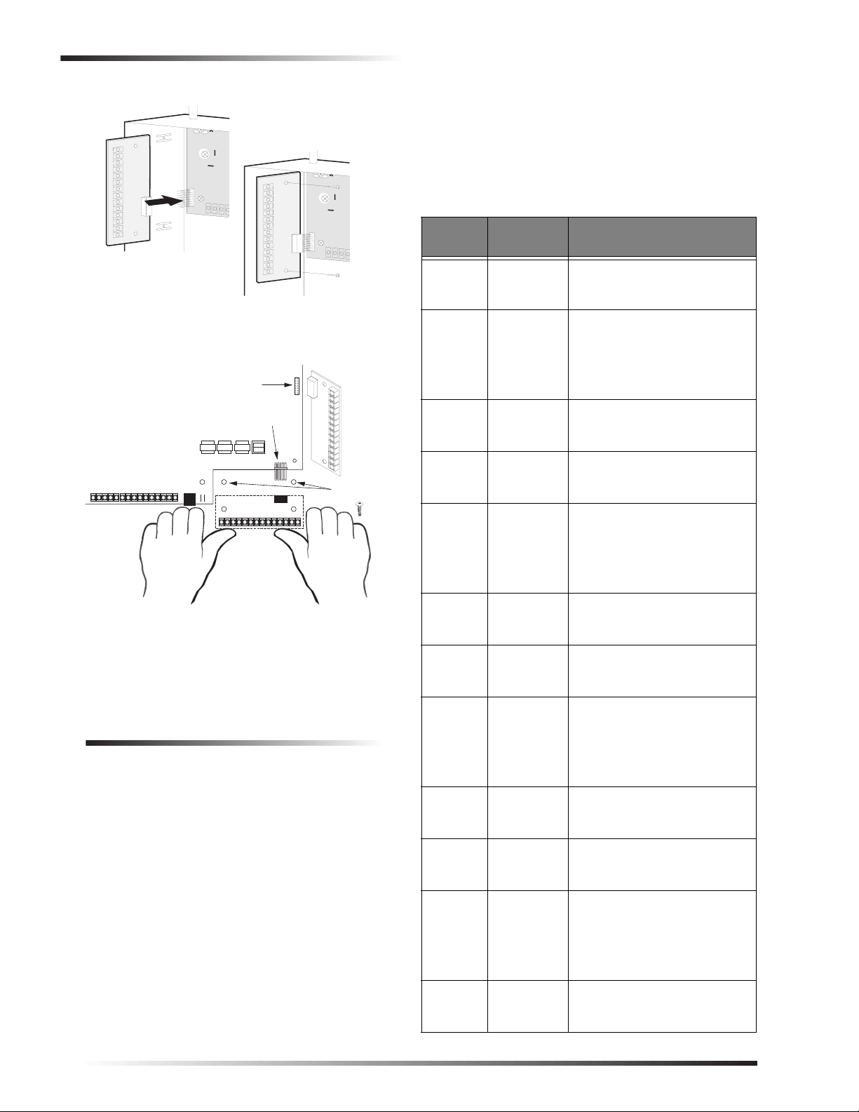
PUSH SNAPCARD CONNECTOR
ONTO PANEL HEADER
SECURE SNAPCARD WITH
TWO SCREWS
Figure 3. Installing the Card in a Concord Express
Panel
SECONDARY EXPANSION
CARD CONNECTOR
PRIMARY EXPANSION
CARD CONNECTOR
CONTROL PANEL
CIRCUIT BOARD
ALIGN BOAR
HOLES WITH
STANDOFFS
EXPANSION CARD
Figure 4. Installing the Card in Advent panel
(2
8543G86B.DSF
Terminal
Number
Description
Use
1 Relay 1 NC Normally closed (N/C) (ope ns on
activation) output 1 dry relay
contact connection.
2 Relay 1
COM
Common (C) side of output 1 dry
relay N/C and N/O contacts
(terminals 1 and 3). Contacts
rated 4A @ 24VDC, 4A @
24VAC, 1A @ 70VAC
maximum.
3 Relay 1 NO Normally open (N/O) (closes on
activation) output 1 dry relay
contact connection.
4 Relay 2 NC Normally closed (N/C) (ope ns on
activation) output 2 dry relay
contact connection.
5 Relay 2
COM
Common (C) side of output 2 dry
relay N/C and N/O contacts
(terminals 4 and 6). Contacts
rated 4A @ 24VDC, 4A @
24VAC, 1A @ 70VAC
maximum.
6 Relay 2 NO Normally open (N/O) (closes on
activation) output 2 dry relay
contact connection.
3. Press firmly to secure the card to the connector.
4. Secure the card to the cabinet with the two supplied screws.
Wiring
Note
A) Class 2, Class 3, and power-limited fire alarm circuits must be installed using FPL, FPLR, FPLP, or
substitute cable permitted by the National Electrical
Code ANSI/NFPA 70. Wire that extends beyond the
cable jacket m ust be separated from all other conductors by a minimum of 1/4-inch or by a nonconductive
barrier.
OR
(B) Class 2, Class 3, and power-limited fire alarm circuit conductors must be installed as Class 1 or higher
circuits.
2
7 Relay 3 NC Normally closed (N/C) (ope ns on
activation) output 3 dry relay
contact connection.
8 Relay 3
COM
Common (C) side of output 3 dry
relay N/C and N/O contacts
(terminals 7 and 9). Contacts
rated 4A @ 24VDC, 4A @
24VAC, 1A @ 70VAC
maximum.
9 Relay 3 NO Normally open (N/O) (closes on
activation) output 3 dry relay
contact connection.
10 Relay 4 NC Normally closed (N/C) (opens on
activation) output 4 dry relay
contact connection.
11 Rela y 4
COM
Common (C) side of output 4 dry
relay N/C and N/O contacts
(terminals 10 and 12). Contacts
rated 4A @ 24VDC, 4A @
24VAC, 1A @ 70VAC
maximum.
12 Relay 4 NO Normally open (N/O) (closes on
activation) output 4 dry relay
contact connection.
Page 3

Programming
Table 1: Wiring Terminal Descriptions
Terminal
Number
13 GND Common ground return
14 +12VDC Auxiliary output regulated DC
Description
Use
connection for 12 VDC supply
output.
power supply. 12 VDC @ 0.5A
maximum.
Note: If this output is used, it
will draw up to 500 mA from the
panel. Remember to include
this current draw when
calculating total panel power.
To wire the card:
1. Unplug the panel AC power transformer and disconnect the backup battery(s).
2. Wire output devices to the card as shown in Figure 5.
3. Connect the backup battery(s) and plug in the panel AC power transformer.
Programming
Outputs must be programmed to communicate with the
panel and to function as desired. For specific output programming information, refer to the panel Installation
Instructions.
Testing
Once installed, the card becomes an integral part of the
panel. W e recommend that you test all hardwire output
devices after programming is completed and whenever an
output device-related problem occurs. Refer to the panel
Installation Instructions or User’ s Manual for output testing
information.
Troubleshooting (all panels)
Table 2: Troubleshooting Hardwire Outputs
Problem Action/Solution
No outputs
activate
One output never
activates.
Wrong output
activates.
1. Check panel/card programming.
2. Check output wiring and connections.
3. Check panel/card power supplies.
4. If used, check the optional external supply powering the output devices.
1. Check panel/card programming for that output.
2. Check output wiring and connections.
3. Check that the outpu t p ro gr ammed tr igger event actually occurs.
4. An output relay may have failed or
been overloaded. Reprogram to use a
different (unused) output or replace the
card.
1. Check panel output programming.
2. Check output device wiring and connections.
4 OUTPUT EXPANSION
SNAPCARD TERMINALS
NC
4
RELAY 2
NO
COM
6
5
NOTE: DO NOT EXCEED OUTPUT
RELAY CONTACT R ATINGS
RELAY 3
NC
* 0.5 AMP MAX. DO NOT EXCEED POWER SUPPLY CAPACITY.
RELAY 1
NC
1
OUTPUT DEVICE
TYPICAL OUTPUT DEVICE
APPLICATION
8588G01B.DSF
Figure 5. Typical 4 Output Expansion SnapCard Wiring
COM
2
CONTROL
(NO)
NO
3
NO
12
limiting resistor)
0.5A MAX
2.0k Ohm
1/2 W
(current
RELAY 4
NC
COM GND
NO
COM
11
10987
TYPICAL LED
INDICATOR APPLICATION
+12V
1413
*
LED
3
Page 4

Specifications
Specifications
Compatibility: Concord, Concord Express, and
Advent panels.
Power Requirements: (From host panel/module) 12 VDC
@ 142 mA typical with all relays
energized (34 mA per relay energized).
Outputs:
Storage Temp: -40° to 140° F (-40° to 60° C).
Operating Temp: 32° to 140° F (0° to 60° C) under
Maximum Humidity: 90% relative humidity,
Dimensions: 2.0” x 5.25” x 0.75” (H x W x D).
Installation: In panel cabinet mounting.
Listings
(for ancillary use only):
Four, panel prog rammab le outputs wi th
“Form-C” relay contacts (COMMON,
N/C, N/O). Relay contacts rated 4A @
24VDC, 4A @ 24VAC, 1A @
70VAC maximum.
One 12 VDC, 500 mA regulated
power output (from the panel)
Power limited to 6 watts.
temporary conditions.
noncondensing.
UL 985 Household Fire Warning
System Units
Notices
FCC Part 15 Information to the User
Changes or modifications not expressly approved by Interactive Technologies, Inc. can void the user’s authority to operate the equipment.
FCC Part 15 Class A
This equipment has been tested and found to comply with the limits for
a class A digital device, pursuant to part 15 of the FCC rules. These
limits are designed to provide reasonable protection against harmful
interference when the equipment is operated in a commercial environment.
This equipment generates, uses, and can radiate radio frequency energy
and, if not installed and used in accordance with the instru ctio n manual,
may cause harmful interference to radio communications. Operation of
this equipment in a residential area is likely to cause harmful interference in which case users will be required to correct the interference at
their own expense.
FCC Part 15 Class B
This equipment has been tested and found to comply with the limits for
a Class B digital device, pursuant to part 15 of the FCC Rules. These
limits are designed to provide reasonable protectio n against interference
in a residential installation.
This equipment generates, uses, and can radiate radio frequency energy
and, if not installed and used in accordance with the instructions, may
cause harmful interference to radio communications. However, there is
no guarantee that interference will not occur in a particular installation.
If this equipment does cause harmful interference to radio or television
reception, which can be determined by turning the equipment off and
on, the user is encouraged to try to correct the interference by one or
more of the following measures:
❑ Reorient or relocate the receiving antenna.
❑ Increase the separation between the equipment and receiver.
❑ Connect the affected equipment and the panel receiver to separate
outlets, on different branch circuits.
❑ Consult the dealer or an experienced radio/TV technician for help.
UL 864 Control Units for Fire
Protective Signaling Devices.
UL 1023 Household Burglar-Alarm
System Units
UL 1610 Central-Station BurglarAlarm Units
(Commercial Burglary)
ULC Canada Commercial Fire/B urglary Warning System
CSFM California State Fire
Marshall
Note
See specific panel
complete UL installation requirements for the system
you are installing.
Installation In st ruct ions
for
2266 Second Street North
North Saint Paul, MN 55109-2900
T: 651/777-2690
F: 651/779-4890
1-800-777-1415
www.itii.com
© 2000 Interlogix™, inc. Interlogix, SnapCard, Concord, and C oncord Express
are trademarks of Interlogix, Inc. ITI, SuperBus, and Advent are registered
trademarks of Interlogix, inc.
4
 Loading...