

Page 1
8Z Input
Expansion SnapCard™
Document Number: 466-1365 Rev. B
September 1998
8543102A.DS4
60-626
60-757
8Z Input Expansion SnapCard
Installation Guidelines
■ Install a 2k ohm EOL resistor for each supervised
hardwire loop.
■ Plug the expansion card into t he Concor d™ pa nel
expansion slot or either the primary or secondary
expansion slot of the Advent™ panel or SuperBus™ 80Z Input/16 Output Module.
■ Use 4-conductor , 22-ga uge or lar ger stranded w ire
from the terminals to the devices.
INSTALLATION
INSTRUCTIONS
Product Summary
The Eight Zone Input Expansion SnapCard™ enables
you to add hardwire input devices to wireless
Concord™ panels and additional hardwire input
devices to Advent™ panels and to SuperBus™ 80Z
Input/16 Output Modules.
The card includes the following:
■ Two 12V two-wire smoke detector loops that pro-
vide power (100mA) to Style B (Class B) smoke
detectors.
■ Six supervised UL Fire rated hardwire loops (2k
ohm EOLR required) that can be used for any
hardwire device including:
Four-wire smoke detectors, fire pulls, water flow
detector switches, gate valve switches, control
valve supervisory switches, butterfly valve
switches, rate-of-rise detectors, carbon monoxide
gas detectors, assorted other gas detectors and
standard burglar devices.
■ False alarm prevention.
When the panel receives an alarm from a smoke
detector, the panel briefly interrupts power to the
smoke loop. The smoke detectors reset and
recheck the alarm.
On Advent™ panels and SuperBus™ 80Z Input/16
Output Modules, this card may be installed into the
primary or secondary expansion slot and in combination with other cards.
Tools Needed (optional)
■ Small and medium size screwdrivers
■ 22-gauge or larger stranded hookup wire
■ Self-tapping metal screws (included)
■ 2K ohm end-of-line (EOL) resistors (included)
Installation
Use the following instructions to install the card, wire
the input devices, and program the panel.
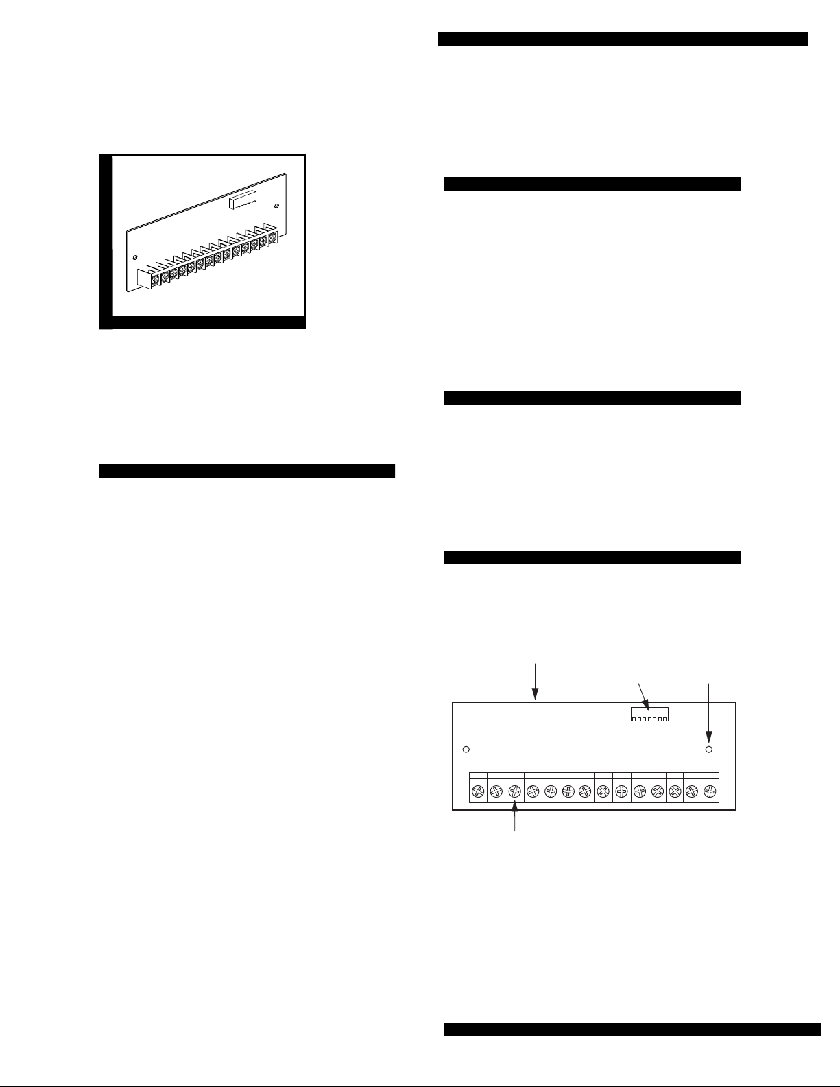
8Z INPUT
EXPANSION SNAPCARD
WIRING
TERMINALS
Figure 1. 8Z Input SnapCard Components
PANEL
CONNECTOR
MOUNTING
SCREW
HOLES (2)
8543116A.DSF
Page 1
Page 2
8Z Input Expans ion SnapCard
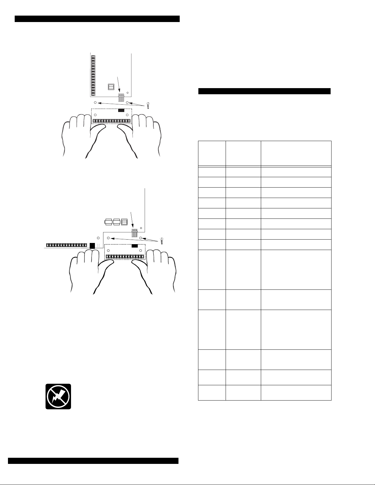
CONTROL PANEL
CIRCUIT BOARD
OPTIONAL
EXPANSION CARD
CONNECTOR
ALIGN BOARD
HOLES WITH
STANDOFFS
(2)
OPTIONAL
EXPANSION CARD
8573G02A.DS4
Figure 2. Installing the Card in Concord Panel
OPTIONAL
EXPANSION CARD
CONNECTOR
CONTROL PANEL
CIRCUIT BOARD
OPTIONAL
EXPANSION CARD
ALIGN BOARD
HOLES WITH
STANDOFFS
(2)
8543G86A.DS4
Figure 3. Installing the Card in Advent Panel and
SuperBus 80Z Input/16 Output Module
CAUTION:
To prevent damaging the panel or card,
always remove panel AC power and disconnect backup batter y before instal lation.
1. Remove panel AC power and disconnect backup battery.
WARNING:
You must be free of all static
electricity when handling electronic components. Touch a bare metal surface before
touching the circuit board.
3. Press firmly to seat the board onto the connector
4. Secure the card to the panel cabinet with the two supplied self-tapping screws.
Wiring
The following table and figur e show s you h ow to wi re
the card. Terminals are numbered left to right
Table 1. Wiring Terminal Descriptions
Term-
inal
Number
1 Zone 1 Hardwire Input zone 1
2 Zone COM Common for zones 1, 2, & 3
3 Zone 2 Hardwire Input zone 2
4 Zone 3 Hardwire Input zone 3
5 Zone 4 Hardwire Input zone 4
6 Zone COM Common for zones 4, 5, & 6
7 Zone 5 Hardwire Input zone 5
8 Zone 6 Hardwire Input zone 6
9 12V Smoke
10 12V Smoke
11 12V Smoke
12 12V Smoke
13 GND Auxiliary power supply ground
14 +12V Out Auxiliary regulated DC power
Description Use
Loop 1
(Positive)
Loop 1
(Negative)
Loop 2
(Positive)
Loop 2
(Negative)
Positive side of 2-wire 12V
smoke lo op 1. Connect up to 20
12V class B smoke detectors
between terminals 9 and 10. (Terminal also supplies +12 VDC
switched power to 4-wire smoke
detectors.)
Negative side of 2-wire 12V
smoke lo op 1.
Positive side of 2-wire 12V
smoke lo op 2. Connect up to 20
12V class B smoke detectors
between terminals 11 and 12.
(Terminal also suppli es +12 VDC
switched power to 4-wire smoke
detectors.)
Negative side of 2-wire 12V
smoke lo op 2.
return.
supply. 12VDC @0.5A ma ximum.
Page 2
2. Align the card holes with the panel standoffs and connector pins as shown in figur e 2 or 3.
Page 3

ZONE
1
ZONE
COM
ZONE2ZONE
3
8Z INPUT EXPANSION
SNAPCARD TERMINALS
ZONE
ZONE
COM
4
ZONE
5
ZONE
6
SMOKE
LOOP 1
+
8Z Input Expansion SnapCard
SMOKE
LOOP 2
+
–
–
GND
+12V
DC
*
OR
NORMALLY
CLOSED
(N/C)
CONTACTS
IN SERIES
2.0k Ohm
EOL RESISTOR
(INSTALL AT LAST DEVICE)
46-467
1
2
*
NORMALLY
OPEN
(N/O)
CONTACTS
IN PARALLEL
TO ANY ZONE INPUT
*
12V
11
12
10
13
14
SMOKE
LOOP 1
+
+
–
–
LISTED
2-WIRE, 12V
SMOKE/HEAT
DETECTOR
SUCH AS
ESL 429CT
USE IN-
AND-OUT
(DAISY-CHAIN)
WIRING
METHODS
ONLY
2.0k Ohm EOL RESISTOR
(INSTALL AT LAST DEVICE)
46-467
SMOKE
LOOP 2
+
–
+
–
9708G01B.DSF
6
3
5
4
7
9
8
*
4-WIRE, 12V
1
4
23
LISTED HARDWIRE
SMOKE/HEAT
DETECTOR SUCH
AS ESL 449AT
USE IN AND OUT
(DAISY-CHAIN)
WIRING METHODS
1
4
23
ONLY
RED
BLACK
GREEN
WHITE
POWER SUPERVISON MODULE
(INSTALL AT LAST DEVICE)
60-798
Figure 4. Typical Card Wiring
To wire the card (all panels):
1. Wire the input devices or smoke detectors as shown in figure 3.
• Use terminals 9 and 10 for the first
two-wire 12V smoke detector loop.
(You can connect up to 20 two-wire
smoke detectors on this loop.)
• Use terminals 11 and 12 for the second
two-wire 12V smoke detector loop if
needed.
2. Use EOL resistors on all hardwire loops as shown.
3. Reconnect the pane l backup battery and restore panel AC power.
Page 3
Page 4

8Z Input Expans ion SnapCard
Programming
Input zones must be programmed to communicate
with the panel and to function as desired. For zone
programming information, refer to the panel Installa-
tion Instructions.
Testing
Once installed, the card becomes an integral part of
the panel. We recommend that you test all input and
output zones after all programming is completed and
whenever a sensor or output related problem occurs.
Refer to the panel Installation Instructions and User’s
Manual for sensor/zone testing information.
Note:
While the sensor test is a valuable installation
and service tool, it only tests sen sor oper atio n fo r
the current conditions. You should perform a sensor test after any change in environment, equipment, or programming.
Troubleshooting (all panels)
4. Check input circuit for wires shorted to ground.
5. Check that ZONE COM (terminals 2,5, & 8) are
used for input zone commons and not
minal 13).
GND (ter-
Specifications
Compatibility: Concord™ and Custom Versions panels, Advent™ and Custom Versions panels, SuperBus™ 80Z Input/16 Output Module.
Power Source: 12 VDC @ 230 ma maximum (from
panel and panel backup battery)
Storage Temperature: -30° to 120° F (-34° to 49° C)
Operating Temperature: 40° to 100° F (4° to 38° C)
Maximum Humidity: 70% relative humidity, noncon-
dencing
Inputs: Six supervised UL Fire rated hardwire loops.
Two 12V two-wire smoke detector loops that provide
power (100mA) to Style B (Class B) smoke detectors.
Outputs: One regulated 12V at 0.5A maximum auxil-
iary power supply.
Dimensions: 2.0” x 5.25” x 0.75” (H x W x D)
The following instructions help you diagnose and fix
problems.
No inputs detected.
1. Check panel programming of all inputs and outputs.
2. Check input device wiring and connections.
One input is never detected.
1. Check panel programming of all inputs and outputs.
2. Check input device operation.
3. Check input device wiring and connections.
Wrong input is detected.
1. Check panel input programming for that input.
2. Check input device wiring and connections.
Sensor Trouble is indicated.
1. Check that the 2.0K ohm end-of-line resistor is correctly installed in the zone loop circuit.
2. Check normally open (N/O) input circuit for a break in the wires.
3. Check normally closed (N/C) input circuit for a short in the wires.
Notices
This device complies with part 15 of the FCC rules. Operation is subject to the following
two conditions:
1. This device may not cause harmful interference.
2. This device must accept any interference received, including interference that may
cause undesired operation.
Changes or modifications not expressly approved by Interactive Technologies, Inc. can
void the users’ authority to operate the equipment.
651/777-2690
651/779-4890
Page 4
ITI is a registered trademar k of Interactive Technologies, Inc. SnapCard, SuperBus,
Concord, and Advent are trademarks of Interactive Technologies, Inc.
 Loading...