

Page 1
4Z Input/2 Output
4Z Input/2 Output Expansion Snap Card
Expansion SnapCard
™
Document Number: 466-1367 Rev. B
September 1998
8543101A.DS4
60-626
60-756
INSTALLATION
INSTRUCTIONS
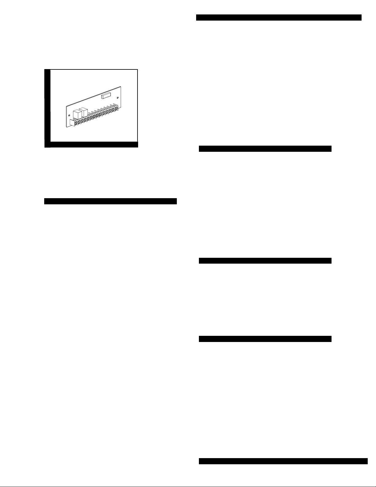
Product Summary
The Four Zone Input/Two Output Expansion SnapCard™ combines the capabilities of the Eight Zone
Input and Four Output Expansion SnapCards. It
allows for Concord™ panel, Advent™ panel, and
Superbus™ 80 Zone Input/16 Output Module expansion.
The card includes the following:
■ One 12V two-wire smoke detector loop that pro-
vides power (100mA) to Style B (Class B) smoke
detectors.
■ Three supervisedUL Fir e rated har dwire loops (2k
ohm EOL resistors required) that can be used for
any hardwire device including:
4-wire smoke detectors, fire pulls, water flow
detector switches, gate valve switches, control
valve supervisory switches, butterfly valve
switches, rate-of-rise detectors, carbon monoxide
gas detectors, assorted other gas detectors and
standard burglar devices.
■ False alarm prevention.
When the panel receives an alarm from a smoke
detector, the panel briefly interrupts power to the
smoke loop. Smoke detectors reset and recheck
the alarm.
■ Two “Form C” contact relays. The relays are con-
trolled by a touchpad or a combination of states
and events in the system.
On Advent™ panels, and Superbus™ 80 Zone Input/
16 Output Modules, this card may be installed into the
primary or secondary expansion slot and in combination with other cards.
Devices may be programmed to perform in various
ways. You can use the touchpad to turn on lights and
open drapes or a garage door. You can program the
system to turn on a closed-circuit-TV (CCTV) camera
during a burglary a larm, turn exit light ing on duri ng a
fire alarm or activate backup cellular phones or longrange radios if primary communications are inoperable.
Installation Guidelines
■ Install a 2k ohm EOL resistor at the end devi ce on
each supervised two-wire hardwire loop.
■ Install a po wer supervision module at the end
device on four-wire smoke loops.
■ Plug the expansion card into t he Concor d™ pa nel
expansion slot or either the primary or secondary
expansion slot of the Advent™ panel or SuperBus™ 80 Zone Input/16 Output Module.
■ Use 4-conductor , 22-ga uge or lar ger stranded w ire
from the terminals to the devices.
Tools Needed (optional)
■ Screwdriver
■ Four-conductor, 22-gauge or larger stranded
hookup wire
■ Thread rolling mounting screws (included)
■ 2K ohm end-of-line (EOL) resistors
Installation
Use the following instructions to install the card, wire
input devices, and program the panel.
Page 1
Page 2
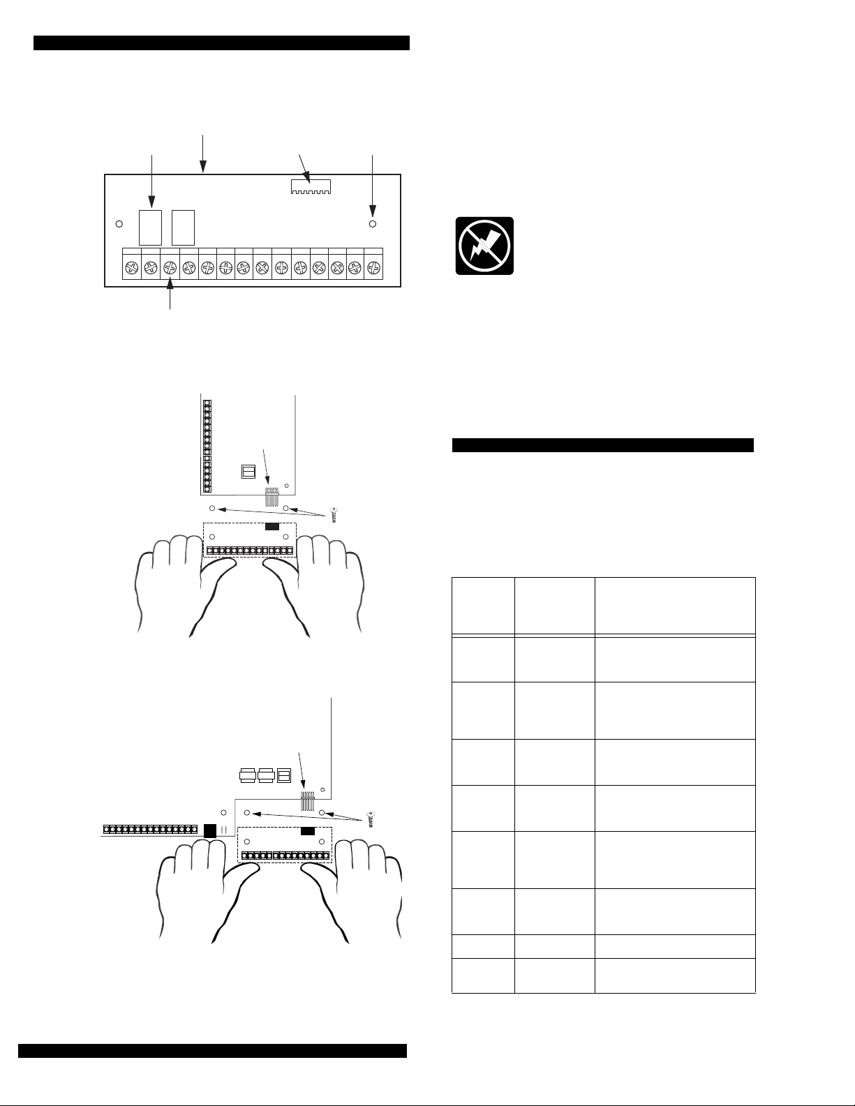
4Z Input/2 Output Expansion SnapCard
4Z INPUT/2 OUTPUT
EXPANSION SNAPCARD
RELAYS (2)
WIRING
TERMINALS
Figure 1. Card Components
PANEL
CONNECTOR
CONTROL PANEL
CIRCUIT BOARD
OPTIONAL
EXPANSION CARD
CONNECTOR
OPTIONAL
EXPANSION CARD
ALIGN BOARD
HOLES WITH
STANDOFFS
(2)
MOUNTING
SCREW
HOLES (2)
8543115A.DSF
CAUTION:
To prevent damaging the panel or card,
always remove panel AC power and disconnect backup battery before installation.
1. Disconnect panel power and backup battery.
WARNING:
You must be free of all static
electricity when handling electronic components. Touch a bare metal surface before
touching the circuit board.
2. Align the card holes with the standoffs and connector pins as shown in figure 2 or 3.
3. Press firmly to secure the board to the connector
4. Secure the card with the two thread rolling metal screws.
Wiring
The following table and figur e show s you h ow to wi re
the card. Terminals are numbered left to right.
Note:
Terminal 11 (SMK+) ca n al so power 4-wire
smoke detectors.
T a ble 1. Card Wiring Terminal Descriptions
8573G02A.DS4
Figure 2. Installing the Card in Concord Panel
OPTIONAL
EXPANSION CARD
CONNECTOR
CONTROL PANEL
CIRCUIT BOARD
OPTIONAL
EXPANSION CARD
ALIGN BOARD
HOLES WITH
STANDOFFS
(2)
8543G86A.DS4
Figure 3. Installing the Card in Advent Panel and
SuperBus 80Z Input/16 Output Modules
Term-
inal
Description Use
Number
1Relay 1NCNormally closed (N/C) (opens on
2Relay 1
3Relay 1NONormally open (N/O) (closes on
4 Relay 2
5Relay 2
6Relay 2NONormally open (N/O) (closes on
7 ZN1 Hardwire Input zone 1
8 ZCOM Common f or hardwire input
COM
NC
COM
activation) output 1 dry relay contact connection.
Common (C) side of output 1 dry
relay N/C and N/O contacts (terminals 1 and 3). Contacts rated
5.0 A @30 VDC maximum.
activation) output 1 dry relay contact connection.
Normally closed (N/C) (opens on
activation) output 2 dry relay contact connection.
Common (C) side of output 2 dry
relay N/C and N/O contacts (terminals 2 and 6). Contacts rated
5.0 A @30 VDC maximum.
activation) output 2 dry relay contact connection.
zones 1, 2, and 3.
Page 2
Page 3

T a ble 1. Card Wiring Terminal Descriptions (Continued)
Term-
inal
Description Use
Number
9 ZN2 Hardwire Input zone 2
10 ZN3 Hardwire Input zone 3
4Z Input/2 Output Expansion Snap Card
11 SMK+ Smoke sensor power supply.
12 SMK- Negative (-) side of 2-wire, 12
13 GND Common ground for 4-wire
14 12VDC Auxiliary DC power supply.
OUTPUT
DEVICE
CONTROL
(N.O.)
*
Switched 12 VDC @ 100 mA
maximum. Positive (+) side of 2wire, 12 VDC smoke loop.
VDC smoke loop.
smoke sensors, and rate-of-rise
heat sensors
12 VDC @ 500 mA maximum.
RELAY 1
COM
N.C.
1
2
OR
NORMALLY
CLOSED
(N/C)
CONTACTS
IN SERIES
IN PARALLEL
N.O.
3
*
NORMALLY
OPEN
(N/O)
CONTACTS
N.C.
4
4Z Input/2 Output
EXPANSION CARD TERMINALS
RELAY 2
N.O.
COM
5
6
ZN1 ZN2 ZN3ZCOM
7
*
1
4
23
1
4
23
9
8
4-WIRE, 12V
LISTED HARDWIRE
SMOKE/HEAT
DETECTOR SUCH
AS ESL 449AT
USE IN AND OUT
(DAISY-CHAIN)
WIRING METHODS
ONLY
10
SMOKE
+
11
GND
-
12
+
+
13
LISTED 2-WIRE,
12V SMOKE/HEAT
–
USE IN-AND-OUT
–
(DAISY-CHAIN)
METHODS ONLY
+12VOUT
14
DETECTOR
SUCH AS
ESL 429AT
WIRING
2.0k Ohm
EOL RESISTOR
49-454
(INSTALL AT LAST DEVICE)
RED
BLACK
GREEN
WHITE
POWER SUPERVISON MODULE
*
TO ANY ZONE INPUT
(INSTALL AT LAST DEVICE)
Figure 4. Typical 4Z Input/2 Output SnapCard Wiring
2.0k Ohm EOL RESISTOR
49-454
(INSTALL AT LAST DEVICE)
12V
60-798
8587G01B.DSF
Page 3
Page 4

4Z Input/2 Output Expansion SnapCard
To wire the card:
1. Disconnect panel power and backup battery.
2. Wire the smoke d etectors or other d evices. Table 2
describes how to wire various devices. Use terminals 11 and 12 for the two-wire 12V smoke detector loop. (Y ou can connect up to 20 two-wire
smoke detectors on this loop.)
3. Use EOL resistors as shown on any hardwire loops.
4. Reconnect the backup battery and panel AC power.
Programming
Input and output zones must be programmed to communicate with the panel and to function as desired.
For zone programming infor m at ion, r e fer to th e pan el
Installation Instructions.
Testing
Once installed, the card becomes an integral part of
the panel. We recommend that you test all input and
output zones after all programming is completed and
whenever a sensor or output related problem occurs.
Refer to the panel Installation Instructions and User’s
Manual for sensor/zone testing information.
Troubleshooting (all panels)
The following instructions help you diagnose and fix
card hardwire input and o utput problems.
Troubleshooting Hardwire Inputs
No inputs detected.
1. Check input device wiring and connections.
2. Check panel input programming.
One input is never detected.
1. Check input device wiring and connections.
2. Check panel input programming.
Wrong input is detected.
1. Check panel input programming.
2. Check input device wiring and connections.
Sensor Trouble is indicated.
1. Check that the 2.0K ohm end-of-line resistor is correctly installed in the zone loop circuit.
2. Check normally open (N/O) input circuit for a break in the wires.
3. Check normally closed (N/C) input circuit for a short in the wires.
4. Check input circuit for wires sho rted to ground.
5. Check that ZCOM (terminal 8) is used for input
zone common and not
GND (terminal 13).
Note:
While the sensor test is a valuable installation
and service tool, it only tests sen sor oper atio n fo r
the current conditions. You should perform a sensor test after any change in environment, equipment, or programming.
Troubleshooting Hardwire Outputs
No outputs activate:
1. Check panel/card programming.
2. Check output wiring and connections.
3. Check panel/card power supplies.
4. If used, check the optional external supply powering the output devices.
One output never activa tes :
1. Check panel/card programming for that output.
2. Check output wiring and connections.
3. Check that the output programmed trigger event actually occurs.
4. An output relay may have failed or been overloaded. Reprogram to use a different (unused)
output or replace the card.
Wrong output activates:
1. Check panel output programming.
2. Check output device wiring and connections.
Page 4
Page 5

Specifications
Compatibility: Concord™ and Custom Versions panels, Advent™ and Custom Versions panels, SuperBus™ 80 Zone Input/16 Output Modules.
Power Source: 12 VDC @ 185 ma maximum (from
panel and panel backup battery ).
Storage Temperature: -30° to 120° F (-34° to 49° C)
Operating Temperature: 40° to 100° F (4° to 38° C)
Maximum Humidity: 70% relative humidity, noncon-
densing.
Inputs: Three supervised UL Fire rated hardwire
zones.
One 12V two-wire smoke detector loop that provides
power (100mA) to Style B (Class B) smoke detectors.
Up to twenty devic es.
Outputs: Two “Form C” contact relays. Contacts rated
5.0 A at 30 VDC maximum (each contact).
Dimensions: 2.0” x 5.25” x 0.75” (H x W x D)
Installation: In panel mounting.
4Z Input/2 Output Expansion Snap Card
Notices
This device complies with part 15 of the FCC rules. Operation is subject to the following
two conditions:
1. This device may not cause harmful interference.
2. This device mus t accept an y inter ference received, includ ing inter fe rence t hat may
cause undesired operation.
Changes or modifications not expressly approved by Interactive Technologies, Inc. can
void the users’ authority to operate the equipment.
651/777-2690
651/779-4890
ITI is a registered trademar k of Interactive Technologies, Inc. SnapCard, SuperBus,
Concord and Advent are trademarks of Interactive Technologies, Inc.
Page 5
Page 6

4Z Input/2 Output Expansion SnapCard
Page 6
 Loading...