

Page 1
Interrogator 200 Audio Verification Module
(AVM) Installation Instructions
Product summary
The Interrogator 200 Audio Verification Module (AVM) (60-677)
gives the central station operator the ability to hear what’s
happening at the premises during an alarm and speak directly
to the system owner. The operator can determine how serious
an alarm is, find out what kind of help is needed, and dispatch
the appropriate assistance.
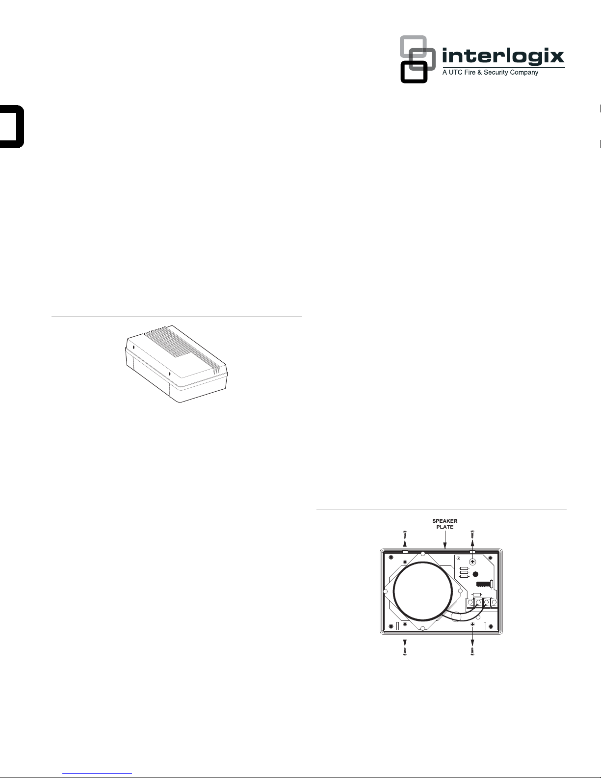
Figure 1: Audio Verification Module
Installation guidelines
Use the following guidelines when installing the AVM:
• You can have no more than two AVMs per panel.
one is 300 feet from the panel, the other AVM can’t use
more than 200 feet of cable.
Tools needed
• Phillips screwdriver
• Mounting screws and anchors (included)
• Drill and bits
• 3-conductor, 22-gauge shielded stranded wire
• 2-conductor, 18-gauge stranded wire
Installation
To mount the AVM:
1. Route both 2 and 3-conductor wire cables from the
module to the panel.
2. Remove the cover screws from the module cover and
rotate it away from the base. Set the cover and screws
aside.
3. Remove the speaker plate screws and lift the speaker
plate off the back box (Figure 2 below).
• Wire speakers (voice terminals) in series and the DC
voltage, ground, and microphone wires in parallel.
• Wiring more than two speakers to the panel voice
terminals or wiring them in parallel can damage the panel.
• Use separate cables for the speakers and the power,
ground, and microphone wires to prevent cross talk
between the microphone and the speaker.
• Use 3-conductor, 22-gauge shielded wire from the AVM
power, ground and microphone to the panel. Shielded
cable reduces electrical noise and cross talk.
• Use 2-conductor, 18-gauge wire from the speakers to the
panel.
• Use a maximum of 500 feet. of cable for all speakers and
microphones. For example, if you’re using two AVMs and
P/N 466-1153 • REV C • January 2011 1
Figure 2: Speaker plate
4. Place the back box on the wall at the desired location and
mark mounting holes (Figure 3 on page 2).
Page 2
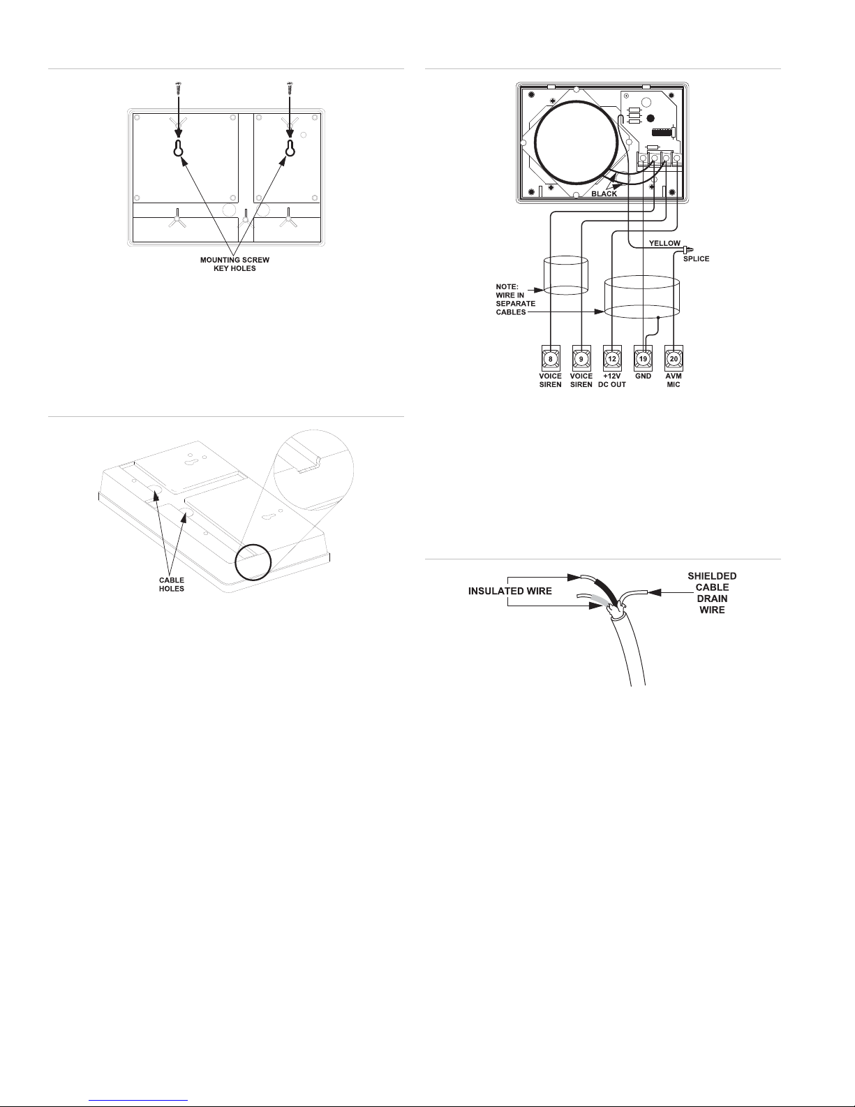
3: Mounting hole locations
Figure
5. Install anchors if needed and secure the back box to the
wall with the enclosed screws.
6. Feed the cables through one of the cable holes in the back
box (Figure 4 below).
Figure 4: Cable holes and channels
Figure 5: AVM wiring connections
4. Splice the yellow wire to the microphone cable.
5. Connect the black speaker wires on the module to the two
center terminals.
7. Align the back box mounting screw key holes with the two
mounting screws and slide down.
8. Level the back box and tighten the mounting screws.
9. Feed the cable through the large hole on the speaker
plate.
10. Replace the speaker plate on the back box.
UltraGard wiring
To wire the AVM to an UltraGard panel:
1. Turn off the panel power switch.
2. Strip about ½ in. from cables and module wires.
6. Connect the shielded cable drain wire (bare wire as shown
in Figure 6 below) to ground terminal 19.
Figure 6: Shielded cable detail
7. Replace the AVM cover and screws.
Powering up
To power up the panel:
1. Make sure all wires are connected properly and securely
crimped.
2. Turn the panel power switch on.
3. Connect terminals as shown in Figure 5 below. Use 18gau
ge wire for speakers and 22-gauge for +12V, ground,
and microphone.
2 Interrogator 200 Audio Verification Module (AVM) Installation Instructions
Programming
Programming the AVM involves entering the following:
• AVM mode of operation
• AVM time-out
Page 3

• AVM access code
Note: UltraGard optional feature number F20 (AVM Enable)
must be turned on to use the AVM. Optional feature number
F00 (Remote Phone Access) must be on to access the AVM
from a remote phone.
AVM modes
The following describes the available AVM operating modes.
One-ring
After reporting an alarm, the panel answers on the first ring. A
5 minute window allows remote access alarm verification after
an alarm is reported. Once the panel has answered, the AVM
access code must be entered (within 20 seconds) to use the
AVM.
Note: If an AVM access code has not been programmed, the
AVM cannot be used in the one-ring mode.
This window is activated after an alarm has been reported and
allows access to the AVM after one ring at the alarm site. No
reports to the central station are allowed during this 5 minute
interval except fire alarms. The 5 minute window is cleared
when the monitoring service operator hangs up using 99 or the
system is disarmed from the customer site during an audio
session.
One-ring silent
Same as one-ring, except on-premises telephones do not ring.
Note: Some electronic phones may ring for about 1/8 of a
second when this mode is selected.
Instant fire siren shutdown
Same as instant, except fire sirens may be shut down at the
customer site (10-second annunciator).
If a fire alarm occurs during either the access time-out interval
(Instant) or the five minute call back window (One-ring), the fire
alarm will be reported by the panel. After report completion, the
AVM will return to the state it was in prior to the fire alarm.
The AVM can be accessed from off-site using the AVM access
code even when no alarm has occurred. If this off-site access
is gained and then an alarm occurs, the panel disconnects
premises phones and reports the alarm to the monitoring
service.
Note: If an AVM access code is not programmed, you cannot
access the AVM.
To accommodate other communication formats and avoid
conflict, the AVM has a programmable (via CS-4000 or
Downloader only) delay period for the annunciation of beeps
that request the audio access code or star (*) telephone
access key. This delay period is programmable from 2 to 300
seconds in 2-second increments. In instant mode, the delay is
in effect when the system has completed its reports and has
released the telephone line to the AVM. In one-ring mode, the
delay is in effect when the system answers the telephone after
one ring. In off-site access, the delay is not in effect.
The AVM mode factory default value is 03 - Instant.
Note: Some electronic phones may ring for about 1/8 of a
second when this mode is selected.
Instant
The CS-4000 trips the panel when it reports an alarm.
Monitoring personnel can then initiate an audio session from a
CS-4000 parallel telephone, without using the AVM access
code.
One-ring Fire Siren Shutdown
Same as one-ring, except fire sirens will be shut down at the
customer site when audio access is gained. Instead of sirens,
the system will announce Fire. Fire. every ten seconds (10second annunciator).
One-ring silent fire siren shutdown
Same as one-ring silent, except fire sirens may be shut down
at the customer site (10-second annunciator).
To set the AVM mode of operation:
In PROGRAM MODE, press BYPASS until AVM MODE is
1.
displayed.
2. Press COMMAND to display AVM MODE - [default or
present AVM mode number].
3. Enter the desired two-digit AVM mode number:
01 - One-ring
02 - One-ring Silent
03 - Instant
09 - One-ring Fire Siren Shutdown
10 - One-ring Silent Fire Siren Shutdown
11 - Instant Fire Siren Shutdown
4. Press COMMAND. AVM MODE - [new mode number] is
displayed.
5. Press FIRE to exit.
Interrogator 200 Audio Verification Module (AVM) Installation Instructions 3
Page 4

Setting the AVM time-out
The AVM time-out determines how long the AVM holds the
telephone line in the instant mode while waiting for the star (*)
telephone access key, after reporting an alarm. The AVM
controls the panel’s telephone line for the duration of the
access time-out period.
The time-out value defaults to 90 seconds and can be set from
30 to 300 seconds, in 2-second increments.
Testing
The panel must be programmed before testing. Refer to the
panel documentation for complete instructions.
When the installation and programming are complete, test the
AVM installation as follows.
UltraGard off-site testing
To set the AVM time-out:
In PROGRAM MODE, press BYPASS until AVM TIME-
1.
OUT is displayed.
2. Press COMMAND to display AVM TIME-OUT - [default or
present time-out in seconds].
3. Enter the desired three-digit AVM time-out (030 to 300
seconds in 2-second increments).
4. Press COMMAND. AVM TIME-OUT - [new time-out] is
displayed.
5. Press FIRE to exit.
Setting the AVM access code
The AVM access code is required by the central station in
order to access the AVM listen-in/talk-back feature for one-ring
mode settings or in non-alarm conditions. AVM access codes
can be any four-digits from 0001 through 9998, except:
• The install, primary, secondary, or arm/disarm access
codes (or their duress codes, if enabled).
• 0000, 1111, or 1234, or similar, which are too simple to
guess.
• 7777, 8888, or 9999, which are reserved phone panic
codes.
• 6s (any number or combination), which are reserved for
sensor bypassing.
The AVM access code default value is blank (****).
You will need a helper and touch-tone phone at an off-site
location to perform this test.
Note: When testing the AVM from an off-site phone, optional
feature numbers F00 (Remote Phone Access) and F20 (AVM
Enable) must be turned on, and the system must be in a nonalarm state. F00 defaults on and F20 defaults off. Optional
feature number F01 (Ring Twice, Hang-up, Ring, Answer)
must be on to work with steps 1 and 2. Otherwise, let the
phone ring 12 times and the panel will pick up, automatically.
To test the module from off-site:
The off-site helper calls the panel, lets the phone ring
1.
twice, and hangs up.
2. The helper must call the panel again in 10 to 40 seconds.
The panel answers System hello.
3. The helper dials the following on the phone:# # AVM
access CODE *. The helper should now be able to hear
you through the AVM.
4. Walk through the area the module covers while speaking
at a normal conversation level.
5. Tell the helper to dial a 1 and speak to you. To return to
listen mode, the helper dials a 3.
6. When testing is complete, have the helper dial 99 and
hang up.
Central station testing
You can also use the central station to test the module.
To enter the AVM access code:
In PROGRAM MODE, press BYPASS until AVM CODE is
1.
displayed.
2. Press COMMAND to display AVM CODE - [present AVM
access code].
3. Enter the desired four-digit AVM access code (0001 to
9998) or press POLICE to clear the displayed code.
4. Press COMMAND. AVM CODE - [new AVM access code]
is displayed.
5. Press FIRE to exit.
4 Interrogator 200 Audio Verification Module (AVM) Installation Instructions
To test the module from the central station:
1. Inform the central station that you will be sending an alarm
and testing an AVM.
2. Give them the programming selections you made for the
panel.
3. Use a touchpad panic button to initiate an auxiliary alarm.
4. The central station operator waits for the alarm to be
reported and initiates an audio session.
Page 5

5. Walk through the AVM area of coverage while speaking at
a normal conversation level.
6. Have the operator speak to you.
7. When testing is complete, the operator will end the
session.
Sound volume
The AVM microphone volume is automatically controlled and is
not adjustable. The speaker volume is preset to full volume.
If it doesn’t work
AVM Communication failure usually occurs because of panel
programming errors. Check the programming selections you
made at the panel.
Specifications
Compatibility UltraGard and Custom Versions
Power requirements 12 VDC, 10 mA (maximum)
Dimensions 6.9" L x 4.9" H x 2.5" D
Color Belgian gray
Regulatory information
Manufacturer UTC Fire & Security Americas Corporation, Inc.
1275 Red Fox Rd., Arden Hills, MN 55112-6943,
USA
FCC compliance This device complies with part 15 of the FCC
rules. Operation is subject to the following two
conditions:
1)This device may not cause harmful
interference.
2)This device must accept any interference
received, including interference that may cause
undesired operation.
Changes or modifications not expressly approved
by Interlogix can void the users’ authority to
operate the equipment
Contact information
www.utcfireandsecurity.com or www.interlogix.com
For customer support, see www.interlogix.com/customer-
support
Copyright © 2011 UTC Fire & Security Company. All rights
reserved.
Interrogator 200 Audio Verification Module (AVM) Installation Instructions 5
 Loading...