

Page 1
Indoor/Outdoor PIR Motion Sensors
Installation Instructions
466-1534G • August 2006
Copyright © 2006, GE Security Inc.
Introduction
This is the GE Indoor/Outdoor PIR Moti on Sensors Installation
Instructions for model numbers:
• 60-639-95R (indoor)
• 60-639-95R-OD (outdoor)
• 60-639-43-EUR (indoor, not investigated for use by UL)
• 60-639-43-ERT-OD (outdoor, not investigated for use by
UL)
Passive-infrared (PIR) motion sensors detect movement within a
specific area by sensing the infrared energy emitted from a body
as it moves across the sensor’s field of view, causing a temperature change in the sensor’s zones. When the sensor detects this
motion, it transmits an alarm signal to the control panel.
Use the indoor sensors to protect large areas and open floor plans
or as backup protection for door/window sensors.
Use the outdoor sensors to identify motion in a protected outdoor
area. Detected motion in this protected area can sound chimes or
turn on outside lights. Do not use the outdoor sensors for intrusion protection.
Features include:
• 35 by 40 ft. (10.7 x 12.2 m) coverage area for standard and
optional pet alley lenses;
• masking kit to block portions of the coverage area;
• three-minute transmitter lockout time after an alarm to
extend battery life;
• cover-activated tamper (an optional wall-activate d tamper is
provided);
• supervisory signal transmitted every 64 minutes to the
control panel;
• sensor low battery reports (trouble) to the control panel; and
• field-selectable sensitivity options.
• Mount the sensor between 5 and 8 ft. (1.5 and 2.4 m) from
the floor (Figure 2). We recommend a height of 7.5 ft. (2.3
m). Higher mounting provides better range, and lower
mounting provides better protection close to the sensor. See
Pet alley lens on page 3.
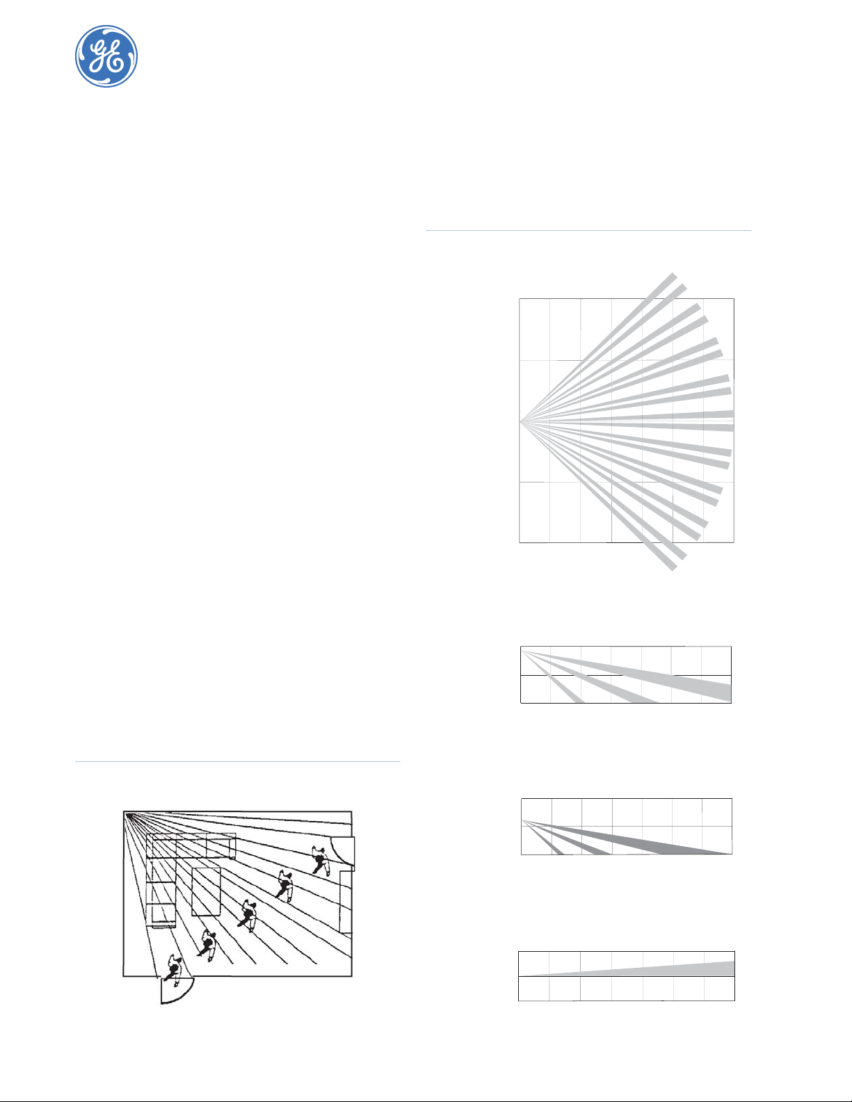
Figure 2. Detection pattern
Top view
20 ft.
6 m
10 ft.
3 m
0 ft.
0 m
10 ft.
3 m
20 ft.
6 m
5 ft.
1.5 m
15 ft.
4.5 m
25 ft.
7.5 m
35 ft.
10.5 m
Indoor sensor installation
Use the following installation guidelines:
• If possible, mount the sensor within 100 ft. (30.5 m) of the
panel. While the transmitter may have a range of 500 ft.
(152.4 m) or more out in the open, the environment at the
installation site can have a significant effect on transmitter
range.
• Position the sensor to protect an area where an intruder is
most likely to walk across the detection pattern. (Figure 1).
Figure 1. Overhead detection pattern
Side view with mounting height of 7.5 ft. (2.3 m)
8 ft. (2.4 m)
4 ft. (1.2 m)
0 ft. (0 m)
Side view with mounting height of 5 ft. (1.5 m)
8 ft. (2.4 m)
4 ft. (1.2 m)
0 ft. (0 m)
Side view with pet alley lens and flush mount
8 ft. (2.4 m)
4 ft. (1.2 m)
0 ft. (0 m)
5 ft.
1.5 m
5 ft.
1.5 m
5 ft.
1.5 m
15 ft.
4.5 m
15 ft.
4.5 m
15 ft.
4.5 m
25 ft.
7.5 m
25 ft.
7.5 m
25 ft.
7.5 m
35 ft.
10.5 m
35 ft.
10.5 m
35 ft.
10.5 m
Page 2
Indoor/Outdoor PIR Motion Sensors
2
Installation Instructions
• Mount the sensor on a rigid surface that is free of vibrations.
• Do not aim the sensor at windows, fireplaces, air conditioners, area heaters, or forced air heating vents. Do not
place it in direct sunlight. Sudden changes in temperature
may trigger a false alarm.
• Do not mount the sensor near duct work or other large
metallic surfaces that may aff ect t he RF signa ls (see Testing
on page 4). Verify actual transmitter range for each installation.
• Mount the sensor permanently on a flat wall or in a corner.
Do not set it on a shelf.
• Mount the sensor on an insulated, outside wall facing in.
• Position the sensor so it faces a solid reference point, such
as a wall.
• Close all windows in an area with an armed motion sensor.
• A pet will trigger a motion sensor. See Pet alley lens on
page 3 to use a motion sensor when pets are present.
You can flush-mount, incline-mount, or corner-mount the sensor
depending on the lens used. Use the optional swivel mount (part
number 60-737) for difficult mounting loca tions (Figure 3).
Note: The wall-tamper switch cannot be used when you mount
the sensor in a corner or on the swivel mount.
Figure 3. Mounting options
Flush mount Inclined mount
To mount the sensor, do the following:
1. To r emove the mounting plate, depress the button on the top
of the sensor (Figure 4) and pull the mounting plate away
from the sensor.
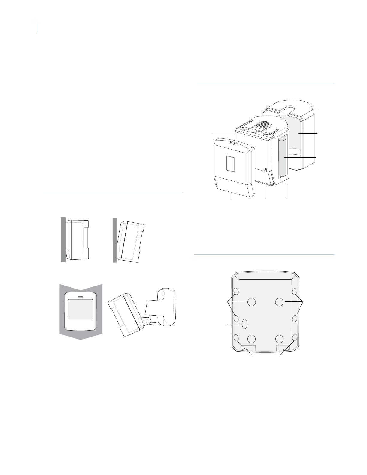
Figure 4. Sensor parts
Sensor
cover
Tabs
Mounting
plate
Tamper
switch
Sensor
body
Lens
Battery
2. Punch out the mounting holes applicable for your installation (Figure 5). Use the lower-side holes for corner
mounting, or the lower-back holes for surface-mounting
with the standard lens. For applications with pets, use the
upper mounting holes and the optional pet alley lens.
Corner mount Swivel mount
Figure 5. Mounting plate knockouts
Pet alley lens
knockouts
Wall tamper
knockout
Standard lens
knockouts
Pet alley lens
knockouts
3. If you want wall-tamper functionality, remove the walltamper knockout (Figure 5).
4. Mark the location of the required holes on the mounting
surface.
5. Use wall anchors and screws to secure the mounting plate in
place. Attach the sensor to the mounting plate.
6. Test the sensor in place (see Testing on page 4), then screw
the housing screw (the smallest screw provided) into the
hole at the top of the mounting plate.
Page 3

3
Lens replacement
To change the lens, do the following:
1. Depress the button on the top of the sensor and pull the
sensor from the mounting plate.
2. Depress the two tabs on the top and the one tab on the
bottom of the sensor body and slide the cover off (Figure 4
on page 2).
3. To remove the lens, gently place pressure on the lens from
the outside of the lens.
4. Align the new lens’s notches with the tabs in the cover.
Install the new lens with the smooth side facing out and the
grooved side facing in.
5. Slide the cover on the sensor and attach the sensor to the
mounting plate.
Pet alley lens
The optional pet alley lens (part number 60-709) provides protection in installations where pets move about freely. See Figure 2
on page 1 for the coverage pattern.
Follow these guidelines for installations with the pet alley lens:
• Mount the sensor 3 to 5 ft. (0.9 x 1.5 m) high. For best
results, install the sensor higher than the highest point the
pet might reach in the detection area.
• If the detection area contains furniture or other objects that
the pet can climb or jump on, either remove these objects,
mount the sensor a safe distance above these objects, or
mask these areas.
• Be sure to flush-mount or corner-mount the sensor with the
back of the sensor parallel to the walls. Do not use the
inclined-mount position because this will tilt the sensor’s
field of view downward.
• Position the sensor so that is has a clear line of sight across
the protected room.
Sensitivity settings
The sensor is set to standard sensitivity at the factory. This sensitivity is preferred for most applications and provides the best
immunity to false alarms.
CAUTION: High sensitivity should only be used in
extremely quiet environments where
thermal transients are not expected.
To cha nge the sensitivity setting, do the following:
1. Depress the button on the top of the sensor and pull the
sensor from the mounting plate (Figure 4 on page 2).
2. Depress the two tabs on the top and the one tab on the
bottom of the sensor body and slide the cover off (Figure 4
on page 2).
3. Looking at the front of the sensor, locate the sensitivity pins
under the battery on the right side (Figure 6).
Figure 6. Sensitivity pins
Standard
High
4. To change to hig h sensitivity, move the shorting jumper to
the pair of pins that are closer to the top of the sensor
(Figure 6).
Note: If the shorting jumper is not used or is placed
incorrectly, the sensor defaults to standard
sensitivity.
5. Walk test the sensor (see Testing) to verify sensitivity. Slide
the cover on the sensor and attach the sensor to the
mounting plate.
Page 4

Indoor/Outdoor PIR Motion Sensors
4
Installation Instructions
Outdoor sensor installation
Use the following guidelines for outdoor installations:
• Use the outdoor sensors for outdoor applications with a
temperature of 10 to 120°F (12 to 49°C).
• Do not use outdoor sensors for intrusion protection because
any human, pet, or heated mechanical motion such as an
automobile can activate the sensor.
• Follow the indoor sensor installation guidelines (see Indoor
sensor installation on page 1), except for the last four items.
• Do not aim the sensor at objects that may be heated excessively by the sun, such as blacktop or dark-colored objects.
• The sensor housing is water-resistant, but not water-proof.
Mount the sensor underneath eaves or porch coverings to
prevent exposure to rain, ice, and direct sunlight.
To mount the sensor, do the following:
1. Determine the mounting location for the sensor. Leave at
least 4 in. (10 cm) of room above the wall mount plate to
attach the sensor .
2. Use the supplied screws and anchors to attach the wallmount plate with the opening for the swivel mount facing
downward.
3. To attach the sensor assembly to the wall-mount plate,
screw the sensor assembly up into the opening in the wallmount plate.
4. To remove the sensor for testing or battery replacement,
slide the front cover of the sensor upward until you can
remove the sensor.
Filter installation
A 1 in. (2.5 cm) piece of lens material is included with the
outdoor sensors. The filter reduces the sensors’ sensitivity to
white light sources (sunlight and head lights) and infrared
sources. Install the filter when you experience unwanted sensor
activations due to these sources.
To install the filter, do the following:
1. Slide the front cover upward untill you can remove the
sensor from its enclosure (Figure 4 on page 2).
2. Depress the button on top of the sensor to remove the
mounting plate.
3. Depress the two tabs on the top and the one tab on the
bottom of the sensor and slide the cover off.
4. Place the sensor on its back and drop the filter into the lens
chamber covering the sensor’s detector.
5. Replace the cover, making sure the filter re mains in the lens
chamber and does not interfere with the attachment of the
cover.
6. Replace the sensor’s mounting plate and install the sensor in
its enclosure.
Programming
Refer to the panel installation instructions for information on
programming the sensor into the panel.
Testing
Testing the sensor includes a walk test, an environment test, and
a final test with the control panel.
Walk test
Walk test the unit from both directions to determine the pattern
boundaries. The edge of the coverage pattern is determined by
the first flash of the LED. This may change slightly depending on
the sensitivity setting.
To walk test the sensor, do the following:
1. Remove the sensor from the mounting plate to activate the
tamper switch and remount the sensor on the mounting plate
to start the 60-second walk test mode.
2. Walk across the coverage pattern to determine the coverage
area, indicated by the LED activation. Each activation
extends walk test mode for an additional 60 seconds. After
60 seconds without motion, walk test mode and the LED
will no longer activate when motion is detected.
When walk test mode has ended, an alarm can be transmitted
only after three minutes have passed since the previous alarm.
This three-minute lockout time reduces unnecessary RF transmissions in high traffic areas and extends battery life.
Note: Excessive use of walk test mode may reduce battery life.
Use only for initial setup and maintenance testing.
Environment test
For indoor sensors, turn on all heating or air conditioning sources
that are normally active during the protection period. Stand away
from the sensor outside the coverage pattern and watch for
alarms.
For outdoor sensors, verify that the sensor’s coverage area does
not extend into undesired areas that might cause unwanted activations. These areas include undesired human, pet, and automobile motion.
Coverage masks
After you complete the walk test and environment test, you can
use the masking labels provided to block detection of problem
areas. The masking labels are cut to match the corresponding
lens segments.
To mask coverage areas, do the following:
1. Determine which detection zone/lens segment needs a
masking label.
2. Peel the appropriate mask label from its backing and apply
it to the inside of the lens segment to be blocked.
Final test
Do a final test to verify radio signal integrity and confirm control
panel programming and response.
To test the sensor with the control panel, do the following:
1. Remove the sensor from the mounting plate to activate the
tamper switch and the sensor’s walk test mode.
2. Replace the sensor on the mounting plate.
3. Place the control panel in sensor test mode. W alk acro ss the
sensor’s detection pattern until the sensor’s LED turns on.
Stop your motion.
4. Listen for the appropriate system response. If the system
does not respond properly , see Troubleshooting on page 5.
Page 5

5
Maintenance
Test the sensor at least once a year to verify proper range and
coverage. Instruct the end user to put the sensor in walk test
mode and walk through the end of the coverage pattern to verify
proper detection.
Battery replacement
When you replace the batteries, observe proper polarity (as
shown in the battery compartment) to avoid damage to the
sensor.
CAUTION: Replace only with two AA 1.5 V alkaline
batteries. Dispose of used batteries
according to the manufacturer’s
instructions and local government
authorities.
To replace the batteries, do the following:
1. Remove the sensor from the mounting plate and slide the
cover off the sensor to reveal the battery compartment.
2. Remove the batteries and replace with the new ones. Be
sure to observe polarity. As you look at the battery compartment, on the left side the positive end is down and on the
right side the positive end is up (Figure 4 on page 2).
3. Wait at least three minutes after installing the batteries
before you activate walk test mode.
Troubleshooting
If the system doesn’t respond correctly when the sensor is activated, follow these guidelines:
• Check sensor programming (refer to the panel’s programming instructions) and reprogram the sensor if necessary.
• Move the sensor to another location and test for correct
response.
To relocate the sensor, do the following:
1. Test the sensor a few inches from the original position.
2. Increase the distance and retest until you find an acceptable
location.
3. Mount the sensor in the new location.
If no location is acceptable, do the following:
1. Test a known good sensor at the same location.
2. If the system does not respond, avoid mounting a sensor at
that location.
3. If the replacement sensor functions, return the problem
sensor for repair.
Page 6

Indoor/Outdoor PIR Motion Sensors
6
Installation Instructions
Specifications
Compatibility Concord, Concord Express, International
Power source 2 AA 1.5 V alkaline batteries
Typical battery life 2 to 4 years at 68°F (20°C) not verified by UL
Transmitter frequency 319.5 MHz
Operating temperature
Indoor sensor
Outdoor sensor
Storage temperature -30 to 140°F (-34 to 60°C)
Maximum relative humidity 90% relative humidity noncondensing
Dimensions (L x W x H) 2.9 x 2.4 x 1.9 in. (74 x 61 x 48 mm)
Sensor models 60-639-43-EUR and 60-639-EUR-OD are
approved for use in the following countries:
Austria Italy
Denmark Netherlands
France Portugal
Germany Spain
Ireland Sweden
Concord, Simon, Euro Simon, Quik Bridge 1
and 2 Channel Receiver, Quik Bridge Euro
Repeater SAW, Quik Bridge International
Loop Receiver, SuperBus 2000 RF Receiver,
SuperBus 2000 433 MHz Receiver
32 to 120°F (0 to 49°C)
10 to 120°F (12 to 49°C)
Manufacturers Declaration of Conformity
Product identification:
Model/type 60-639-43-EUR and 60-639-43-EUR-OD
Category Indoor and outdoor PIR motion sensors
Brand GE Security
Manufacturer: GE Security
EU representative: GE Security, B.V.
Concerning R&TTE
A sample of the product
has been tested by:
Standards used: I-ETS 3000 220 (10.1993) EN50130-4 (1995)
Test report: T14152-1-02SM 98639220
Means of conformity
We declare under our sole responsibility that this product is in conformity with
Directive 93/68/EEC (CE Marking) and complies to the essential requirements of
1999/5/EC (R&TTE) based on test results using (non)-harmonized standards in
accordance with the Directives mentioned.
1275 Red Fox Road
Arden Hills, MN 55112
Kelvinstraat 7
6003 DH Weert
The Netherlands
Mike Product Services KTL Arnhem
EN50130-4/A1 (1998)
EN60950, 1992 (A1, A2,
A3, A4, A11)
IEC950, 2nd ed. (A1, A2,
A3, A4)
98639250
Toll-free: 888.GESECURity (888.437.3287 in the US, including Alaska and Hawaii; Puerto Rico; Canada).
Outside the toll-free area: Contact your local dealer.
Technical support
www.gesecurity.com
 Loading...