

Page 1

TPC-1070
Intel Touch Panel Computer
with High Luminance 10.4"
SVGA TFT LCD
User Manual
Page 2

Copyright
The documentation and the software included with this product are copyrighted 2007 by Advantech Co., Ltd. All rights are reserved. Advantech
Co., Ltd. reserves the right to make improvements in the products
described in this manual at any time without notice. No part of this manual may be reproduced, copied, translated or transmitted in any form or
by any means without the prior written permission of Advantech Co., Ltd.
Information provided in this manual is intended to be accurate and reliable. However, Advantech Co., Ltd. assumes no responsibility for its use,
nor for any infringements of the rights of third parties, which may result
from its use.
Acknowledgements
Intel and Pentium are trademarks of Intel Corporation.
Microsoft Windows and MS-DOS are registered trademarks of
Microsoft Corp.
All other product names or trademarks are properties of their respective
owners.
Part No. 2003107000 1st Edition
Printed in Taiwan March 2007
TPC-1070 User Manual ii
Page 3

Product Warranty (2 years)
Advantech warrants to you, the original purchaser, that each of its products will be free from defects in materials and workmanship for two years
from the date of purchase.
This warranty does not apply to any products which have been repaired or
altered by persons other than repair personnel authorized by Advantech,
or which have been subject to misuse, abuse, accident or improper installation. Advantech assumes no liability under the terms of this warranty as
a consequence of such events.
Because of Advantech’s high quality-control standards and rigorous testing, most of our customers never need to use our repair service. If an
Advantech product is defective, it will be repaired or replaced at no
charge during the warranty period. For out-of-warranty repairs, you will
be billed according to the cost of replacement materials, service time and
freight. Please consult your dealer for more details.
If you think you have a defective product, follow these steps:
1. Collect all the information about the problem encountered. (For
example, CPU speed, Advantech products used, other hardware
and software used, etc.) Note anything abnormal and list any
onscreen messages you get when the problem occurs.
2. Call your dealer and describe the problem. Please have your manual, product, and any helpful information readily available.
3. If your product is diagnosed as defective, obtain an RMA (return
merchandize authorization) number from your dealer. This allows
us to process your return more quickly.
4. Carefully pack the defective product, a fully-completed Repair and
Replacement Order Card and a photocopy proof of purchase date
(such as your sales receipt) in a shippable container. A product
returned without proof of the purchase date is not eligible for warranty service.
5. Write the RMA number visibly on the outside of the package and
ship it prepaid to your dealer.
iii
Page 4

Declaration of Conformity
CE
This product has passed the CE test for environmental specifications
when shielded cables are used for external wiring. We recommend the use
of shielded cables. This kind of cable is available from Advantech. Please
contact your local supplier for ordering information.
FCC Class A
Note: This equipment has been tested and found to comply with the limits
for a Class A digital device, pursuant to part 15 of the FCC Rules. These
limits are designed to provide reasonable protection against harmful
interference when the equipment is operated in a commercial environment. This equipment generates, uses, and can radiate radio frequency
energy and, if not installed and used in accordance with the instruction
manual, may cause harmful interference to radio communications. Operation of this equipment in a residential area is likely to cause harmful interference in which case the user will be required to correct the interference
at his own expense.
Technical Support and Assistance
Step 1. Visit the Advantech web site at www.advantech.com/support
where you can find the latest information about the product.
Step 2. Contact your distributor, sales representative, or Advantech's cus-
tomer service center for technical support if you need additional
assistance. Please have the following information ready before
you call:
- Product name and serial number
- Description of your peripheral attachments
- Description of your software (operating system, version, application software, etc.)
- A complete description of the problem
- The exact wording of any error messages
TPC-1070 User Manual iv
Page 5

Safety Instructions
1. Read these safety instructions carefully.
2. Keep this User's Manual for later reference.
3. Disconnect this equipment from any AC outlet before cleaning.
Use a damp cloth. Do not use liquid or spray detergents for cleaning.
4. For plug-in equipment, the power outlet socket must be located
near the equipment and must be easily accessible.
5. Keep this equipment away from humidity.
6. Put this equipment on a reliable surface during installation. Dropping it or letting it fall may cause damage.
7. The openings on the enclosure are for air convection. Protect the
equipment from overheating. DO NOT COVER THE OPENINGS.
8. Make sure the voltage of the power source is correct before connecting the equipment to the power outlet.
9. Position the power cord so that people cannot step on it. Do not
place anything over the power cord.
10. All cautions and warnings on the equipment should be noted.
11. If the equipment is not used for a long time, disconnect it from the
power source to avoid damage by transient overvoltage.
12. Never pour any liquid into an opening. This may cause fire or electrical shock.
13. Never open the equipment. For safety reasons, the equipment
should be opened only by qualified service personnel.
14. If one of the following situations arises, get the equipment checked
by service personnel:
a. The power cord or plug is damaged.
b. Liquid has penetrated into the equipment.
c. The equipment has been exposed to moisture.
d. The equipment does not work well, or you cannot get it to work
according to the user's manual.
e. The equipment has been dropped and damaged.
f. The equipment has obvious signs of breakage.
15. DO NOT LEAVE THIS EQUIPMENT IN AN ENVIRONMENT
WHERE THE STORAGE TEMPERATURE MAY GO BELOW -
v
Page 6

20° C (-4° F) OR ABOVE 60° C (140° F). THIS COULD DAMAGE THE EQUIPMENT. THE EQUIPMENT SHOULD BE IN A
CONTROLLED ENVIRONMENT.
16. CAUTION: DANGER OF EXPLOSION IF BATTERY IS
INCORRECTLY REPLACED. REPLACE ONLY WITH THE
SAME OR EQUIVALENT TYPE RECOMMENDED BY THE
MANUFACTURER, DISCARD USED BATTERIES ACCORDING TO THE MANUFACTURER'S INSTRUCTIONS.
The sound pressure level at the operator's position according to IEC 7041:1982 is no more than 70 dB (A).
DISCLAIMER: This set of instructions is given according to IEC 704-1.
Advantech disclaims all responsibility for the accuracy of any statements
contained herein.
Wichtige Sicherheishinweise
1. 1. Bitte lesen sie Sich diese Hinweise sorgfältig durch.
2. Heben Sie diese Anleitung für den späteren Gebrauch auf.
3. Vor jedem Reinigen ist das Gerät vom Stromnetz zu trennen. Verwenden Sie Keine Flüssig-oder Aerosolreiniger. Am besten dient
ein angefeuchtetes Tuch zur Reinigung.
4. Die NetzanschluBsteckdose soll nahe dem Gerät angebracht und
leicht zugänglich sein.
5. Das Gerät ist vor Feuchtigkeit zu schützen.
6. Bei der Aufstellung des Gerätes ist auf sicheren Stand zu achten.
Ein Kippen oder Fallen könnte Verletzungen hervorrufen.
7. Die Belüftungsöffnungen dienen zur Luftzirkulation die das Gerät
vor überhitzung schützt. Sorgen Sie dafür, daB diese Öffnungen
nicht abgedeckt werden.
8. Beachten Sie beim. AnschluB an das Stromnetz die AnschluBwerte.
9. Verlegen Sie die NetzanschluBleitung so, daB niemand darüber
fallen kann. Es sollte auch nichts auf der Leitung abgestellt werden.
10. Alle Hinweise und Warnungen die sich am Geräten befinden sind
zu beachten.
TPC-1070 User Manual vi
Page 7

11. Wird das Gerät über einen längeren Zeitraum nicht benutzt, sollten
Sie es vom Stromnetz trennen. Somit wird im Falle einer Überspannung eine Beschädigung vermieden.
12. Durch die Lüftungsöffnungen dürfen niemals Gegenstände oder
Flüssigkeiten in das Gerät gelangen. Dies könnte einen Brand bzw.
elektrischen Schlag auslösen.
13. Öffnen Sie niemals das Gerät. Das Gerät darf aus Gründen der elektrischen Sicherheit nur von authorisiertem Servicepersonal geöffnet werden.
14. Wenn folgende Situationen auftreten ist das Gerät vom Stromnetz
zu trennen und von einer qualifizierten Servicestelle zu überprüfen:
a - Netzkabel oder Netzstecker sind beschädigt.
b - Flüssigkeit ist in das Gerät eingedrungen.
c - Das Gerät war Feuchtigkeit ausgesetzt.
d - Wenn das Gerät nicht der Bedienungsanleitung entsprechend funk-
tioniert oder Sie mit Hilfe dieser Anleitung keine Verbesserung erzielen.
e - Das Gerät ist gefallen und/oder das Gehäuse ist beschädigt.
f - Wenn das Gerät deutliche Anzeichen eines Defektes aufweist.
15. VOSICHT: Explisionsgefahr bei unsachgemaben Austausch der
Batterie.Ersatz nur durch densellben order einem vom Hersteller
empfohlene-mahnlichen Typ. Entsorgung gebrauchter Batterien
navh Angaben des Herstellers.
16. ACHTUNG: Es besteht die Explosionsgefahr, falls die Batterie auf
nicht fach-männische Weise gewechselt wird. Verfangen Sie die
Batterie nur gleicher oder entsprechender Type, wie vom Hersteller
empfohlen. Entsorgen Sie Batterien nach Anweisung des Herstellers.
Der arbeitsplatzbezogene Schalldruckpegel nach DIN 45 635 Teil 1000
beträgt 70dB(A) oder weiger.
Haftungsausschluss: Die Bedienungsanleitungen wurden entsprechend
der IEC-704-1 erstellt. Advantech lehnt jegliche Verantwortung für die
Richtigkeit der in diesem Zusammenhang getätigten Aussagen ab.
vii
Page 8

TPC-1070 User Manual viii
Page 9

Contents
Chapter 1 General Information ....................................... 2
1.1 Introduction ....................................................................... 2
1.2 Specifications .................................................................... 2
1.2.1 System Kernel ................................................................ 2
1.2.2 I/O Ports ......................................................................... 3
1.2.3 Safety and Environment ................................................. 3
1.3 LCD Specifications ........................................................... 3
1.4 Touchscreen Specifications............................................... 4
1.5 Power................................................................................. 4
1.6 I/O Port Arrangement........................................................ 5
1.7 Panel Mounting ................................................................. 6
1.8 Dimensions and cutout ...................................................... 7
Chapter 2 System Setup.................................................. 10
Chapter 3 System Engine................................................ 14
Chapter 4 Software Configuration ................................ 16
4.1 Utilities & Drivers........................................................... 16
4.2 Advantech COM Driver Installation ............................... 18
4.3 Watchdog Timer (WDT) Driver Installation .................. 26
Chapter 5 Windows XP Embedded ............................... 36
5.1 EWF ................................................................................ 36
5.2 HORM............................................................................. 36
5.3 Advantech Utilities.......................................................... 37
Figure 1.1:I/O port arrangement .................................... 5
Figure 1.2:Panel Mounting ............................................ 6
Figure 1.3:Dimensions ................................................... 7
Figure 2.1:Install CompactFlash memory card ............ 10
Figure 2.2:Power connector ......................................... 10
Figure 2.3:Power receptor and button pin assignments 11
Figure 2.4:Touchscreen Calibration - 1 ....................... 12
Figure 2.5:Touchscreen Calibration - 2 ....................... 12
Figure 3.1:Main Board Connector ............................... 14
4.1.1 Intel Chipset Software Installation Utility ................... 16
4.1.2 VGA Drivers (Intel(R) Graphics Driver) ..................... 16
4.1.3 Intel PRO Network Drivers/software .......................... 16
4.1.4 Advantech COM Driver ............................................... 17
4.1.5 Touchscreen Driver ...................................................... 17
4.1.6 Watchdog Timer Driver ............................................... 17
4.3.1 Installing the TPC-1070 Watchdog Timer Driver .......27
4.3.2 How to Use the TPC-1070 Watchdog Timer ............... 32
5.3.1 Version Information ..................................................... 37
5.3.2 OSLock and OSUnLock .............................................. 38
ix Table of Contents
Page 10

5.3.3 HORM ......................................................................... 38
Appendix A Serial Port Settings........................................ 40
A.1 COM1/ COM3 Connector Definition ............................. 40
A.2 COM4 Setting ................................................................. 40
Appendix B Watchdog Timer on WinCE ........................ 44
B.1 DeviceIOControl ............................................................. 44
B.2 How to Use the Control Code ......................................... 46
B.3 Examples ......................................................................... 48
Appendix C Watchdog Timer Programming................... 52
C.1 Overview ......................................................................... 52
C.2 Watchdog Timer Programming....................................... 53
Figure C.1:Watchdog timer programming procedure .. 53
Table C.1:Watchdog Timer Registers ......................... 54
C.3 Example Programs .......................................................... 55
Appendix D Accessory Kit Assembly................................ 62
D.1 CompactFlash to IDE Transfer Kit ................................. 62
D.2 USB Driver Installation Notice....................................... 64
Figure D.1:Adapter Board and IDE Cable ................... 62
Figure D.2:Connecting Adapter Board & IDE Cable .. 62
Figure D.3:CompactFlash Slot .................................... 63
Figure D.4:Insert the Adapter Board into the CF slot .. 63
Figure D.5:Inserted Adapter Board ............................. 63
Figure D.6:Connect the CD-ROM via the IDE Cable . 64
Figure D.7:Plug Power Line into CD-ROM Drive ...... 64
Appendix E HDD Kit Assembly........................................ 66
Figure E.1:Removing the Rear HDD Cover ................ 66
Figure E.2:Removing the Top Screws ......................... 66
Figure E.3:Installing the HDD ..................................... 66
Appendix F Touchscreen Installation & Configuration . 68
F.1 Driver Installation ........................................................... 68
F.2 Uninstall the Driver......................................................... 70
F.3 Touchscreen Calibration ................................................. 71
Figure F.1:Setup.exe .................................................... 68
Figure F.2:Install - Wizard .......................................... 68
Figure F.3:Install – License Agreement ...................... 69
Figure F.4:Install – Completed .................................... 69
Figure F.5:Uninstall -1 ................................................. 70
Figure F.6:Uninstall -2 ................................................. 70
Figure F.7:Uninstall -3 ................................................. 71
Figure F.8:Standard Calibration -1 .............................. 72
Figure F.9:Standard Calibration -2 .............................. 72
Figure F.10:Standard Calibration -3 ............................ 73
Figure F.11:Advanced Calibration -1 ......................... 74
Figure F.12:Advanced Calibration -2 .......................... 74
TPC-1070 User Manual x
Page 11

Figure F.13:Plot Calibration Data ................................ 75
Figure F.14:Draw ........................................................ 76
Figure F.15:Clear Screen ............................................. 76
Figure F.16:Option ...................................................... 77
Appendix G Fuse Specifications ........................................ 80
G.1 Fuse Specifications.......................................................... 80
G.2 Fuse Replacement ........................................................... 80
Figure G.1:Fuse Replacement ...................................... 80
xi Table of Contents
Page 12

TPC-1070 User Manual xii
Page 13

2
1
CHAPTER
General Information
Sections include:
• Introduction
• Specifications
• LCD Specifications
• Touchscreen Specifications
• Power
• I/O Ports Arrangement
• Panel Mounting
• Dimensions & Cutout
Page 14

Chapter 1 General Information
This chapter gives the background information about the TPC-1070.
1.1 Introduction
The TPC-1070 touch panel computer is state-of-the-art HMI (Human
Machine Interface). This 10.4” display operator interface is an x86-based
platform with these key features:
Fanless:
By using a low power processor, the system does not have to rely on fans,
which often are unreliable, and causes dust to circulate inside the equipment.
Bright Display:
The bright TFT LCD display suits industrial demands for clear interfaces.
Powerful Communication Capability:
The TPC-1070 provides powerful IO interface for easily communicating
with other devices. The IO interface includes serial ports, RS-485 port,
parallel port, Ethernet and USB 2.0 support.
Embedded Windows Support:
In addition to the OS support of Windows 2000 and Windows XP,
Advantech offers platform support for Windows CE and XP embedded.
1.2 Specifications
1.2.1 System Kernel
CPU: Intel Pentium M, Celeron M (clock rate 1.4GHz/ 1GHz)
BIOS: Award 4Mbit flash memory
South Bridge: Intel 855GME
VGA: VGA: Intel 855GME
Ethernet: TPC-1070H-P1E (LAN1: Intel 82562, LAN2: Intel 82541);
TPC-1070H-C1E (LAN1: Intel 82562, LAN: Intel 82551)
Watchdog timer: W83627 watchdog timer; 1.6 second timeout period
IDE: 2 EIDE channels support one IDE compact flash socket on board
and one 44 pin (2mm) connector.
TPC-1070 User Manual 2
Page 15

1.2.2 I/O Ports
3 serial ports: RS-232 (COM1, COM3) and RS-232/422/485 (COM4)
2 RJ-45 Ethernet port:
TPC-1070H-P1E, LAN 1(10/100BaseT); LAN 2(10/100/1000BaseT)
TPC-1070H-C1E, LAN 1(10/100BaseT); LAN 2(10/100BaseT)
1 PS/2 port: 6-pin mini-DIN ports for keyboard and mouse
2 USB ports: compliant with USB 2.0
1 Compact Flash Slot: TypeII
1 PCI-104
1.2.3 Safety and Environment
Safety
FCC Class A and CE certificated
BSMI certificated
The front bezel is compliant with NEMA 4
Environment
Operating Temperature: 0~50 degrees Celsius
Storage temperature: -20~60 degrees Celsius
Humidity: 10~95% @ 40 relative humidity (non-condensing)
Vibration: 1Grms (5~500Hz)
3 Chapter 1
Page 16

1.3 LCD Specifications
Display Type
Size (diagonal)
Maximum Resolution
Maximum colors
Pixel Pitch (W x H)
Viewing Angle
Luminance (cd / m
Contrast Ratio
Operating Temperature
Backlight
Backlight Life Time
2
)
TFT color LCD
10.4”
800 x 600 (SVGA)
260K
0.264 x 0.264 mm
-70~70° (H), -60~50° (V); CR>=10
400
500
-20~70° C (Ambient)
2 CCFL
50,000 hours
Note There might be several bright or dark pixels on the
LCD. This comes from the production of the LCD.
Such phenomenon is claimed to be normal according to the LCD manufacturers.
TPC-1070 User Manual 4
Page 17

1.4 Touchscreen Specifications
Touchscreen Type
Base Glass Construction
Resolution
Light Transmission
Controller
Power Rating
Durability
Resistive
Tempered Glass
1024 x 1024
75% typical
RS232 Interface
3.3 to 5V
100 million touches
1.5 Power
Input voltage: 18 ~ 32 Vdc (the fuse will be open circuit as input level
exceeds 33Vdc)
Typical: 24V@2.5A (60W)
5 Chapter 1
Page 18
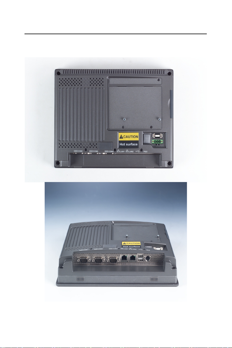
1.6 I/O Port Arrangement
The arrangement of the I/O ports is shown in Figure 1.1.
Figure 1.1: I/O port arrangement
TPC-1070 User Manual 6
Page 19
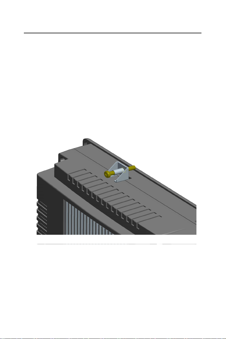
1.7 Panel Mounting
1. There is a piece of adhesive waterproof gasket on the Mg-AL
front bezel. Make sure the waterproof gasket is in position
before installing the TPC-1070 to the panel opening.
2. Install the TPC-1070 to the panel opening.
3. Find out the eight clampers and eight long screws in the
accessory pack. Hook those clampers to those holes around the
four sides of the bezel. Insert the screws to every clamper and
fasten them. These screws will then push on the mounting panel
and fix the unit.
4. The mounting panel thickness is suggested to be less than 10mm
(0.236 inch).
Figure 1.2: Panel Mounting
7 Chapter 1
Page 20
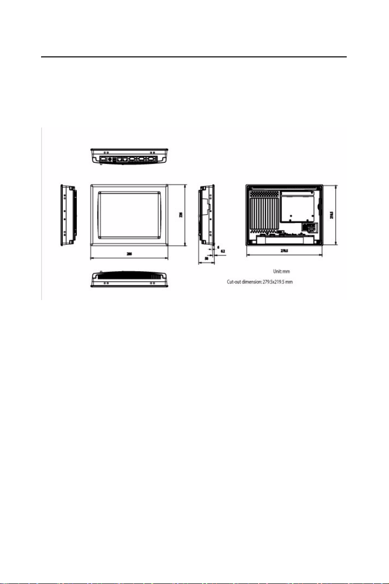
1.8 Dimensions & Cutout
Weight :: 3.5 Kg (without HDD)
Dimensions: 286 x 226 x 58mm (WxHxD)
Cutout: 279.5 x 219.5 mm (suggested)
Figure 1.3: Dimensions
TPC-1070 User Manual 8
Page 21

2
2
CHAPTER
System Setup
Page 22
Chapter 2 System Setup
This chapter provides a brief explanation for operating the TPC-1070. It
is easy to make the TPC-1070 start working with the below step-by-step.
Step 1: Unpack the TPC-1070 package. Please check the packing list at
the beginning of this manual.
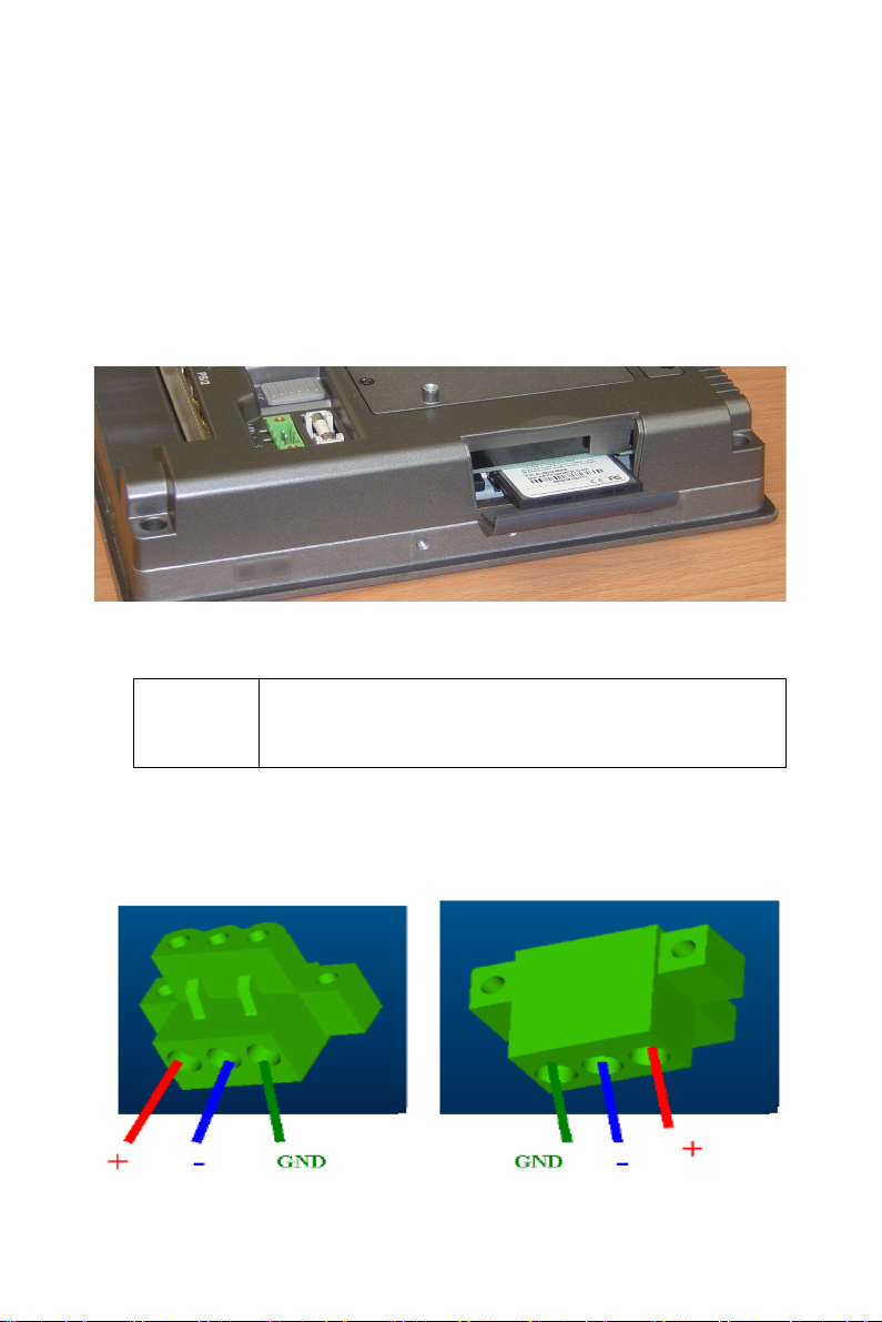
Step 2: Install a CompactFlash containing windows CE, embedded Windows XP or other operating system.
Figure 2.1: Install CompactFlash memory card
Warning It is suggested to turn OFF system power as plug in
or pull out the memory card, though the CompactFlash memory is supposed to be hot swappable.
Step 3: Connect the power connector to the 24VDC power lines. The
power lines can either be of some power adapter or in-house power
source.
Figure 2.2: Power connector
TPC-1070 User Manual 10
Page 23
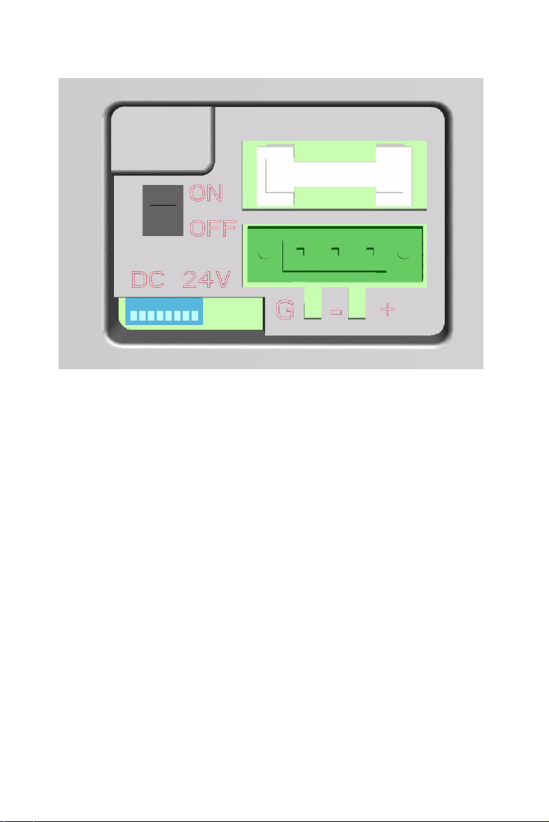
Figure 2.3: Power receptor and button pin assignments
Step 4: Plug the power lines to the system power receptor.
Step 5: Push the power button to power on the system as the figure 2.4.
Step 6: Calibrate the touchscreen. Please go to:
“Start”
Æ
”Settings”Æ”Control Panel” as the figure 2.5. Then, click the
tab “Stylus -> "Calibration" -> "Recalibrate” to calibrate by selecting the
standard calibration or advanced calibration.
If your operating system is Windows CE, the details of the procedure are
described in following section.
11 Chapter 2
Page 24
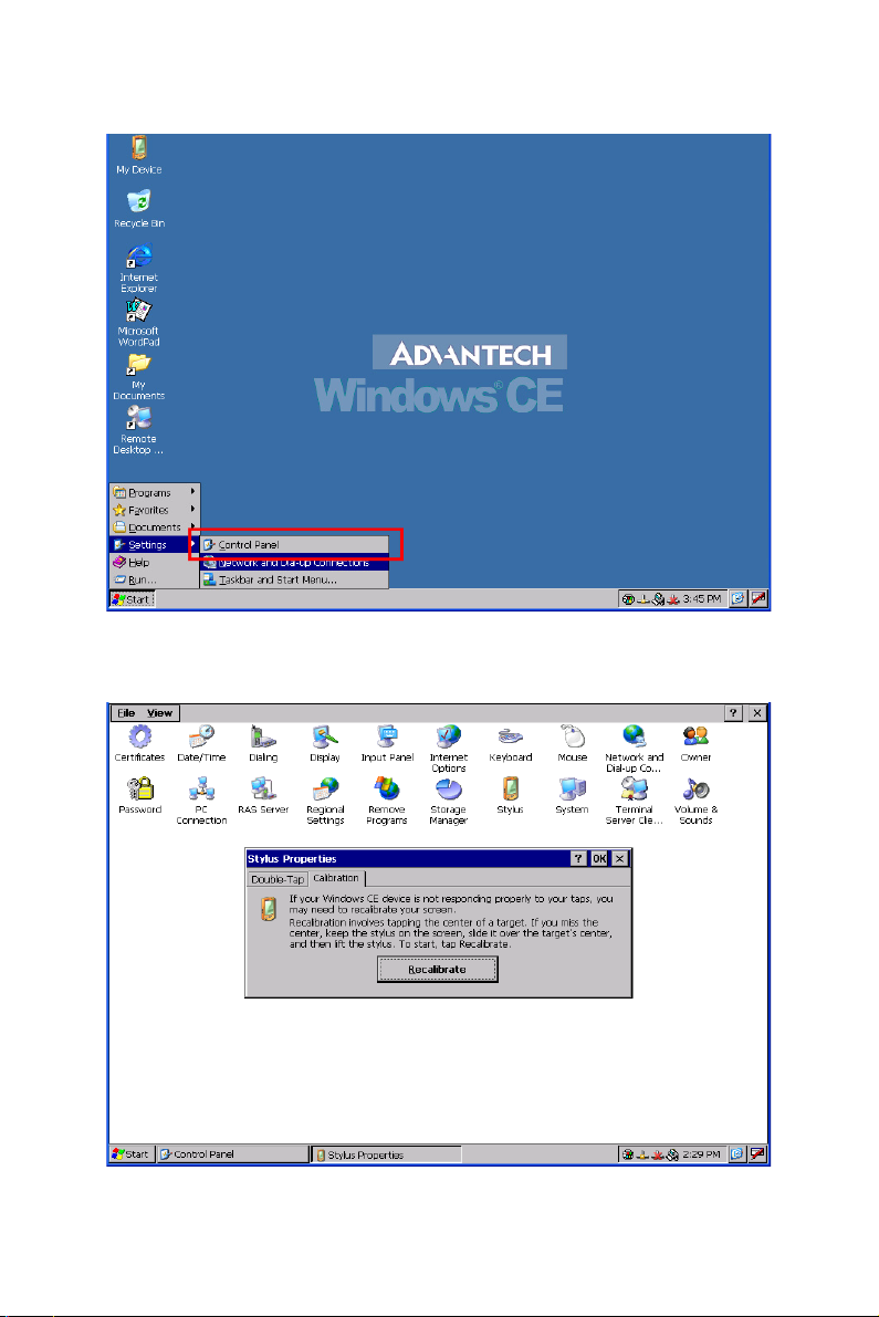
Figure 2.4: Touchscreen Calibration - 1
Figure 2.5: Touchscreen Calibration - 2
TPC-1070 User Manual 12
Page 25

2
3
CHAPTER
System Engine
Page 26
Chapter 3 System Engine
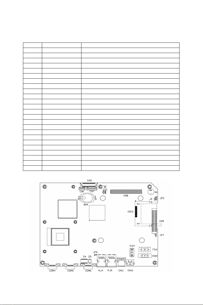
Main Board Connector and Jumper Setting List
Label Function Description
CN5 LVDS LCD Internal 18bit LVDS LCD Connector
CN6 LCD POWER LCD INVERTER Connector
CN7 TOUCH Internal Touch screen Connector
CN8 PCI-104 PCI-104
CN9 IDE Connector IDE connector for 40pin 2.5îinternal HDD
CN10 PWR DC IN DC Power in Connector, HOUSING 5.08 MM 3P
CN11 USB Two USB Type-A Female to on panel.
CN12 PS/2 KB/MS PS/2 connector for KB/MS
CN13 CF Compact-Flash socket
COM4 COM1 Serial port:COM1 RS232
COM5 COM2 Serial port:COM2 RS232
COM6 COM3 Serial port:COM3 RS232/422/485
RJ4 LAN1 ICH4M+82562EZ 10/100
RJ5 LAN2 10/100 82551QM / GIGA 82541PI
BH4 Battery Battery socket
JP5 PCI-104 PWR Selection of PCI-104 Power
JP6 CLEAR CMOS CLEAR CMOS
J4 I2C I2C connector
S4 COM4 MODE1 Setting COM4 RS232/422/485 mode
S5 COM4 MODE2 Setting COM4 RS422 Master or Slave mode
S6 IRQ selection IRQ selection for CAN circuit
SP4 Buzzer Buzzer socket
SW4 POWER SWITCH System Power Switch
SW5 Address selection Address selection for CAN circuit
Figure 3.1: Main Board Connector
TPC-1070 User Manual 14
Page 27

2
4
CHAPTER
Software Configuration
Sections include:
• Utilities & Drivers
• Advantech COM Driver Installation
• Watchdog Timer Driver Installation
Page 28

Chapter 4 Software Configuration
A support CD-ROM for TPC-1070 is available and along with the product. There are related utilities and drivers for TPC-1070 included. Please
install the Chipset INF driver, VGA graphics driver, LAN driver, audio
driver, Advantech.com driver,
(WDT) driver sequentially.
Touchscreen driver and Watchdog Timer
4.1 Utilities & Drivers
The following utilities and drivers are provided for TPC-1070. You can
also find the updated utilities and drivers from the support website.
4.1.1 Intel Chipset Software Installation Utility
Path: \TPC-1070H\Driver\INF\English (for English version)
\TPC-1070H\Driver\INF\Multilanguage (for Multilanguage)
Available for the OS’s below:
• Microsoft Windows 2000
• Microsoft Windows XP
4.1.2 VGA Drivers (Intel(R) Graphics Driver)
Path: \TPC-1070H\Driver\VGA\
Available for the OS’s below:
• Microsoft Windows 2000
• Microsoft Windows XP
4.1.3 Intel PRO Network Drivers/software
Path: \TPC-1070H\Driver\LAN\
Available for the OS’s below:
• Microsoft Windows 2000
• Microsoft Windows XP
TPC-1070 User Manual 16
Page 29

4.1.4 Advantech COM Driver
Path: \TPC-1070H\Driver\Advantech COM\
Available for the OS’s below:
• Microsoft Windows 2000
• Microsoft Windows XP
4.1.5 Touchscreen Driver
Path: \TPC-1070H\Driver\PenMount\
Available for the OS’s below:
• Microsoft Windows 2000
• Microsoft Windows XP
4.1.6 Watchdog Timer Driver
Path: \TPC-1070H\Driver\WDT\8362x
Available for the OS’s below:
• Microsoft Windows 2000
• Microsoft Windows XP
17 Chapter 4
Page 30

4.2 Advantech COM Driver Installation
A com port named COM3 or COM4 on TPC-1070 is Advantech Special
com port. Please follow the steps below to install the driver.
Step 1: Insert the companion CD-ROM into your CD-ROM drive. Open
the directory: \TPC-1070H\Driver\Advantech COM\
Step 2: Use Windows Explorer (or Windows Run command) to execute
PCI_ICOM.EXE from the companion CD-ROM.
TPC-1070 User Manual 18
Page 31

Step 3: Click Next to continue installation.
Step 4: Click Next to continue installation.
19 Chapter 4
Page 32

Step 5: Click uninstall icon to remove ?PCI Serial Port
TPC-1070 User Manual 20
Page 33

Step 6: Click the scan for hardware changes icon to remove ?PCI Serial
Port
21 Chapter 4
Page 34

Step 7: Found New Hardware and Click Next to continue installation.
TPC-1070 User Manual 22
Page 35

Step 8: Click Finish the Advantech PCI Serial Port to continue.
Step 9: Then, found New Hardware and Click Next to continue.
23 Chapter 4
Page 36

Step 10: Click Finish the Advantech PCI-1602 Serial SlaveBridge to
continue installation.
TPC-1070 User Manual 24
Page 37

Step 11: Found New Hardware and Click Next to continue installation.
Step 12: Click Finish the Advantech PCI Serial Port to continue.
25 Chapter 4
Page 38

4.3 Watchdog Timer (WDT) Driver Installation
In order to ensure reliable and fail-safe performance, TPC-1070 has a
built-in Watchdog Timer to handle unexpected system failures. TPC1070 provides the drivers and a utility to activate and configure the timer
for Windows2000/XP operating systems. The following is a brief introduction, using Windows2000 as an example, for the installation and configuration procedures.
TPC-1070 User Manual 26
Page 39

4.3.1 Installing the TPC-1070 Watchdog Timer Driver
Step 1: Insert the companion CD-ROM into your CD-ROM drive. Open
the directory: \WDT\8362x\W2K_XP.
Step 2: Use Windows Explorer (or Windows Run command) to execute
SETUP.EXE from the companion CD-ROM.
27 Chapter 4
Page 40

Step 3: Click Next to proceed.
TPC-1070 User Manual 28
Page 41

Step 4: Click Next to confirm the customer information.
Step 5: Select Advantech [W83627HF] Watchdog Timer and click Next.
.
29 Chapter 4
Page 42

Step 6: Click Next to confirm selecting the Typical setup type.
Step 7: Click Next to proceed.
TPC-1070 User Manual 30
Page 43

Step 8: Click Finish to complete the procedure.
Step 9: Click OK to restart the system and activate the Watchdog Timer.
31 Chapter 4
Page 44

4.3.2 How to Use the TPC-1070 Watchdog Timer
Step 1: Open the Control Panel, click Watchdog Service Configuration.
Step 2: Click the Start Service button.
TPC-1070 User Manual 32
Page 45

Step 3: Click Setting to select the setting page.
Step 4: Select the Timer Span that meets your application requirement.
33 Chapter 4
Page 46

Step 5: Click Enable to enable the setting.
Step 6: Check the Start watchdog service on boot to enable the Watchdog
timer to start automatically after the system boots every time.
Step 7: Click OK, then the configuration procedure is finished.
Note Use Advantech WDT Driver.WDT was
enable,and WDT LED was 1Hz glisten.
TPC-1070 User Manual 34
Page 47

2
5
CHAPTER
Windows XP Embedded
Sections include:
• EWF
• HORM
• Advantech Utilities
Page 48

Chapter 5 Windows XP Embedded
TPC-1070 is in support of embedded windows platform. This section is
to state the important features, EWF and HORN, provided in windows
XP embedded.
5.1 EWF
EWF stands for Enhanced Write Filter. It provides an upper filter in the
storage device driver stack that redirects disk write operations to volatile
(RAM) or non-volatile (disk) storage. EWF protects a volume from write
access. The benefits are as the following.
Write-protect one or more partitions on your system.
Enable read-only media, such as CD-ROM or flash, to boot and run.
Prolong the lifespan of write-sensitive storage, such as CompactFlash.
TPC-1070 XPE provides EWF RAM RDG mode on system partition. All
wirte to system partition will be redirected to RMA once this mode is
enabled. This mode is manually enabled by customers after they finish
all their changes on system such as installing their applications or adjusting system setting.
Advantech provides a pair of utilities to operate EWF, OSLock and
OSUnLock. The setting is stated in the section later.
5.2 HORM
HORM stands for Hibernate Once Resume Many. In HORM environment, a single hibernation file is used to boot the system repeatedly. To
set a HORM environment, please follow the steps below.
Please make sure EWF is disabled. You can run OSUnLock to disable
EWF.
Enable hibernation support:
Run ‘power options’ in control panel, and then select ‘Enable Hibernation’ in hibernation pane.
TPC-1070 User Manual 36
Page 49

Enable EWF:
Run OSLock, and then system reboot automatically.
Open those software that customers want to directly use after system
resume from hibernation.
Hibernate via Advantech HORM utility:
Please Click Start Menu->All Programs->Advantech->HORM
HORM environment remains all along unless the following events occur:
Run EWF commit command (ewfmgr c: -commit) and then reboot sys-
tem.
Select “Discard hibernation file” by clicking F8 when system is starting
up
Also, HORM cannot fit your system if free space in C partition is not
enough. The hibernation file required is dependent on the RAM size you
use on the system. In other words, the hibernation file is 512MB that is
the same as memory size used on TPC-1070H-P1E or TPC-1070H-C1E.
5.3 Advantech Utilities
TPC-1070 provides the useful utilities for users to configure the HORM
and EWF.
5.3.1 Version Information
Start menu-> All Programs -> Advantech
This states the current XPE runtime information including hardware plat-
form, version, build number, release date, XPE QFEs installed in component database and XP Pro Patches you installed manually.
37 Chapter 5
Page 50

5.3.2 OSLock and OSUnLock
The two utilities assist users to enable or disable EWF. Please go to Start
Menu-> All Programs-> Advantech. The default setting of EWF is disabled. Users can protect C partition from any disk writing via OSLock
that is to enable EWF RAM REG Mode. In this mode, any changes on C
partition including modification on files or registry will be redirected to
memory, thus these changes will be discarded in the next system startup.
To exit this environment is via OSUnLock. Please visit MSDN website
for further information about EWF.
5.3.3 HORM
This is to create HORM environment. Please go to Start Menu-> All Programs-> Advantech. This utility firstly dismounts all local physical volumes that are not protected by EWF. It requires users to input the volume
list.
Please follow the steps before running this utility to create full HORM
environment.
Enable Hibernation via Power Options in Control Panel
Make C: partition EWF-enabled via OSLock
Make sure that all volumes to be dismounted are not in use.
TPC-1070 User Manual 38
Page 51

2
A
APPENDIX
Serial Port Settings
Page 52

Appendix A Serial Port Settings
A.1 COM1/ COM3 Connector Definition
1
6
Pin Signal
1 NDCD
2 NRX
3NTX
4 NDTR
5GND
6 NDSR
7NRTS
8 NCTS
9 NRI
5
9
A.2 COM4 Setting
The serial port COM4 on the TPC-1070 is adjustable. It can be set to RS232, RS-422 or RS-485. This port is designed with auto data flow control
capability. In other word, the TPC-1070 can automatically detect the data
flow direction at this port when the two wired RS-485 communication is
activated.
TPC-1070 User Manual 40
Page 53

1
6
Note: indicates the switch jumper
S4
2
34567890 12
S5
1
5
9
RS232
ON
S5
S4
ON
4321098765 21
RS485
ON
2176543 21098
ON
S5S4
RS422-MASTER
ON
S5
S4
ON
165432 10987 2
RS422-SLAVE
ON
ON
PIN RS-232 RS-422 RS-485
1 NDCD TX- D2 NRX TX+ D+
3NTX RX+
4 NDTR RX5GND
6 NDSR
7NRTS
8 NCTS
9 NRI
41 Appendix A
Page 54

TPC-1070 User Manual 42
Page 55

2
B
APPENDIX
Watchdog Timer
on WinCE 5.0
Page 56

Appendix B Watchdog Timer on WinCE
There is a built-in Watchdog timer on Windows CE 5.0 for TPC-1070. You
can access it through WIN32 API. TPC-1070 provides a WDT driver to
allow users to enable/disable the Watchdog timer. The driver name is
“WDT1:”. Programmers must open this driver before using the resources.
Then programmers can use DeviceIOControl functions to enable/disable
Watchdog timer. The introduction below includes the DeviceIOControl, the
definition of the parameter and an example.
B.1 DeviceIOControl
This function sends a control code directly to a specified device driver,
causing the corresponding device to perform the specified operation.
BOOL DeviceIoControl(
HANDLE hDevice,
DWORD dwIoControlCode,
LPVOID lpInBuffer,
DWORD nInBufferSize,
LPVOID lpOutBuffer,
DWORD nOutBufferSize,
LPDWORD lpBytesReturned,
LPOVERLAPPED lpOverlapped );
Parameters:
hDevice
[in] Handle to the device that is to perform the operation. Call the CreateFile function to obtain a device handle.
dwIoControlCode
[in] Specifies the control code for the operation. This value identifies the
specific operation to be performed and the type of device on which the
operation is to be performed. No specific values are defined for the dwIoControlCode parameter. However, the writer of a custom device driver can
define IOCTL_XXXX control codes, per the CTL_CODE macro. These
TPC-1070 User Manual 44
Page 57

control codes can then be advertised, and an application can use these
control codes with DeviceIoControl to perform driverspecific functions.
lpInBuffer
[in] Long pointer to a buffer that contains the data required to perform the
operation. This parameter can be NULL if the dwIoControlCode parameter specifies an operation that does not require input data.
nInBufferSize
[in] Size, in bytes, of the buffer pointed to by lpInBuffer.
lpOutBuffer
[out] Long pointer to a buffer that receives the operation.s output data.
This parameter can be NULL if the dwIoControlCode parameter specifies
an operation that does not produce output data.
nOutBufferSize
[in] Size, in bytes, of the buffer pointed to by lpOutBuffer.
lpBytesReturned
[out] Long pointer to a variable that receives the size, in bytes, of the data
stored into the buffer pointed to by lpOutBuffer. The lpBytesReturned
parameter cannot be NULL. Even when an operation produces no output
data, and lpOutBuffer can be NULL, the DeviceIoControl function makes
use of the variable pointed to bylpBytesReturned. After such an operation, the value of the variable is without meaning.
lpOverlapped
[in] Ignored; set to NULL.
Return Values
Nonzero indicates success. Zero indicates failure. To get extended error
information, call GetLastError.
45 Appendix B
Page 58

B.2 How to Use the Control Code
There are 6 control codes for the operation codes in the WDT driver.
IOCTL _WDT_ENABLE:
Enables the Watchdog timer on your application. By default, if the
Watchdog timer is enabled, the WDT driver will automatically trigger
itself after the specified period and your application does not need to trigger the Watchdog timer in this situation.
lpInBuffer : unused.
nInBufferSize: unused.
lpOutBuffer: unused.
nOutBufferSize: unused.
IOCTL _WDT_DISABLE:
Disables the Watchdog time on your application.
lpInBuffer : unsed.
nInBufferSize: unused.
lpOutBuffer: unused.
nOutBufferSize: unused.
IOCTL_WDT_STROBE:
Triggers the Watchdog. If your application uses IOCTL_WDT_ENABLE
to enable the Watchdog first and then sends IOCTL_WDT_REBOOT to
the WDT driver, your application must trigger the Watchdog once during
the Watchdog timer period. If your application has not triggered at the
specified period, the device will reboot automatically.
lpInBuffer: unused.
nInBufferSize: unused.
lpOutBuffer: unused.
nOutBufferSize: unused.
TPC-1070 User Manual 46
Page 59

IOCTL_WDT_GETTIMEOUT:
Gets the Watchdog time setting.
lpInBuffer: unused.
nInBufferSize: unused.
lpOutBuffer: The DWORD pointer to your Watchdog time setting. The
Watchdog time setting is just a number. 0 means 2 seconds, 1 means 5
seconds, 2 means 10 seconds, 3 means 15 seconds, 4 means 30 seconds, 5
means 45 seconds and 6 means 60 seconds. The default setting is 5 seconds.
nOutBufferSize: unused.
IOCTL_WDT_SETTIMEOUT:
Sets the Watchdog time setting.
lpInBuffer : The DWORD pointer to your Watchdog time setting. The
Watchdog time setting is just a number. 0 means 2 seconds, 1 means 5
seconds, 2 means 10 seconds, 3 means 15 seconds, 4 means 30 seconds, 5
means 45 seconds and 6 means 60 seconds. The default setting is 5 seconds.
nInBufferSize:.unused.
lpOutBuffer: unused.
nOutBufferSize: unused.
IOCTL_WDT_REBOOT:
If you want your application to trigger the Watchdog by itself, please use
IOCTL_WDT_REBOOT to notify the WDT driver. Otherwise, the WDT
will trigger itself automatically.
lpInBuffer :unused.
nInBufferSize: unused.
lpOutBuffer: unused.
nOutBufferSize: unused.
47 Appendix B
Page 60

B.3 Examples
#define WDT_CODE(ID)
CTL_CODE(FILE_DEVICE_UNKNOWN,ID,
METHOD_BUFFERED, FILE_ANY_ACCESS)
#define IOCTL_WDT_ENABLE WDT_CODE (0x900)
#define IOCTL_WDT_DISABLE WDT_CODE(0x901)
#define IOCTL_WDT_STROBE WDT_CODE(0x902)
#define IOCTL_WDT_GET_TIMEOUT WDT_CODE(0x903)
#define IOCTL_WDT_SET_TIMEOUT WDT_CODE(0x904)
#define IOCTL_WDT_REBOOT WDT_CODE(0x905)
// for compatibility reasons, you can define IOCTL as below:
// #define IOCTL_WDT_ENABLE 0x1001
// #define IOCTL_WDT_DISABLE 0x1002
// #define IOCTL_WDT_STROBE 0x1003
// #define IOCTL_WDT_GETTIMEOUT 0x1004
// #define IOCTL_WDT_SETTIMEOUT 0x1005
// #define IOCTL_WDT_REBOOT 0x1006
HANDLE m_hWDT=NULL;
TCHAR szClassName[60];
// assign the WDT driver name
wsprintf(szClassName, TEXT("WDT1:"));
// Open the WDT driver
m_hWDT = CreateFile(szClassName, GENERIC_READ
GENERIC_WRITE, 0, NULL, OPEN_EXISTING,
FILE_ATTRIBUTE_NORMAL, NULL);
if ( m_hWDT == INVALID_HANDLE_VALUE ) {
DebugMsg(CString("WDT driver fail"));
return;
}
DWORD dwTemp;
DWORD nIndex=2;
TPC-1070 User Manual 48
Page 61

// Set the Watchdog Timer as 10 seconds. Number 2 means 10 seconds.
DeviceIoControl(m_hWDT, IOCTL_WDT_SET_TIMEOUT, &nIndex,
sizeof(nIndex), NULL, 0, &dwTemp, NULL);
// Enable the Watchdog timer
DeviceIoControl(m_hWDT, IOCTL_WDT_ENABLE, NULL, 0, NULL,
0, &dwTemp, NULL);
While (1) {
// do your job here.
Sleep(8000);
DeviceIoControl(m_hWDT, IOCTL_WDT_STROBE, NULL,0,
NULL, 0, &dwTemp, NULL);
}
DeviceIoControl(m_hWDT, IOCTL_WDT_DISABLE, NULL, , NULL,
0, &dwTemp, NULL);
CloseHandle(m_hWDT);
49 Appendix B
Page 62

TPC-1070 User Manual 50
Page 63

2
C
APPENDIX
Watchdog Timer
Programming
Page 64

Appendix C Watchdog Timer
Programming
C.1 Overview
The TPC-1070 cards’ watchdog timer can be used to monitor system software operation and take corrective action if the software fails to function
after the programmed period. This section describes the operation of the
watchdog timer, and how to program it.
The watchdog timer is built into the super I/O controller W83627HF. It
provides the following functions for user programming:
• Can be enabled and disabled by user's program.
• Timer can be set from 1 to 255 seconds or 1 to 255 minutes.
• Generates an interrupt or resets signal if the software fails to reset the
timer after time-out.
TPC-1070 User Manual 52
Page 65

C.2 Watchdog Timer Programming
The I/O port address of the watchdog timer is 2E(hex) and 2F(hex), 2E
(hex) is the address port. 2F(hex) is the data port. You must first assign
the address of register by writing address value into address port 2E(hex),
then write/read data to/from the assigned register through data port 2F
(hex).
Figure C.1: Watchdog timer programming procedure
53 Chapter C
Page 66

Table C.1: Watchdog Timer Registers
Address of
register (2E)
Read/Write Value (2F)
87 (hex) ----- Write this address to I/O address
07 (hex) write Write 08 (hex) to select register of
30 (hex) write Write 01 (hex) to enable the function
F5 (hex) write Set seconds or minutes as units for
Write 0 to bit 3: set second as counting unit. [default]
Write 1 to bit 3: set minute as counting unit
F6 (hex) write 0: stop timer [default]01~FF (hex):
F7 (hex) rd/wr Bit 6: Write 1 to enable keyboard to
AA (hex) ----- Write this address to I/O port 2E
Attribute Description
and
description
port 2E (hex) twice to unlock the
W83627HF
watchdog timer.
of the watchdog timer. Disabled is
set as default.
the timer.
The amount of the count, in seconds
or minutes, depends on the value
set in register F5 (hex). This number
decides how long the watchdog
timer waits for strobe before generating an interrupt or reset signal.
Writing a new value to this register
can reset the timer to count with the
new value.
reset the timer, 0 to disable.[default]
Bit 5: Write 1 to generate a timeout
signal immediately and automatically return to 0. [default=0] Bit 4:
Read status of watchdog timer, 1
means timer is "time out".
(hex) to lock the watchdog timer.2
TPC-1070 User Manual 54
Page 67

C.3 Example Programs
1. Enable watchdog timer and set 10 sec. as timeout interval
;----------------------------------------------------------Mov dx,2eh ; Unlock W83627HF
Mov al,87h
Out dx,al
Out dx,al
;----------------------------------------------------------Mov al,07h ; Select registers of watchdog timer
Out dx,al
Inc dx
Mov al,08h
Out dx,al
;----------------------------------------------------------Dec dx ; Enable the function of watchdog timer
Mov al,30h
Out dx,al
Inc dx
Mov al,01h
Out dx,al
;----------------------------------------------------------Dec dx ; Set second as counting unit
Mov al,0f5h
Out dx,al
Inc dx
In al,dx
And al,not 08h
Out dx,al
;----------------------------------------------------------Dec dx ; Set timeout interval as 10 seconds and start counting
Mov al,0f6h
55 Chapter C
Page 68

Out dx,al
Inc dx
Mov al,10
Out dx,al
;----------------------------------------------------------Dec dx ; lock W83627HF
Mov al,0aah
Out dx,al
2. Enable watchdog timer and set 5 minutes as timeout interval
;----------------------------------------------------------Mov dx,2eh ; unlock W83627H
Mov al,87h
Out dx,al
Out dx,al
;----------------------------------------------------------Mov al,07h ; Select registers of watchdog timer
Out dx,al
Inc dx
Mov al,08h
Out dx,al
;----------------------------------------------------------Dec dx ; Enable the function of watchdog timer
Mov al,30h
Out dx,al
Inc dx
Mov al,01h
Out dx,al
;----------------------------------------------------------Dec dx ; Set minute as counting unit
Mov al,0f5h
TPC-1070 User Manual 56
Page 69

Out dx,al
Inc dx
In al,dx
Or al,08h
Out dx,al
;----------------------------------------------------------Dec dx ; Set timeout interval as 5 minutes and start counting
Mov al,0f6h
Out dx,al
Inc dx
Mov al,5
Out dx,al
;----------------------------------------------------------Dec dx ; lock W83627HF
Mov al,0aah
Out dx,al
3. Enable watchdog timer to be reset by mouse
;----------------------------------------------------------Mov dx,2eh ; unlock W83627H
Mov al,87h
Out dx,al
Out dx,al
;----------------------------------------------------------Mov al,07h ; Select registers of watchdog timer
Out dx,al
Inc dx
Mov al,08h
Out dx,al
;----------------------------------------------------------Dec dx ; Enable the function of watchdog timer
57 Chapter C
Page 70

Mov al,30h
Out dx,al
Inc dx
Mov al,01h
Out dx,al
;----------------------------------------------------------Dec dx ; Enable watchdog timer to be reset by mouse
Mov al,0f7h
Out dx,al
Inc dx
In al,dx
Or al,80h
Out dx,al
;----------------------------------------------------------Dec dx ; lock W83627HF
Mov al,0aah
Out dx,al
4. Enable watchdog timer to be reset by keyboard
;----------------------------------------------------------Mov dx,2eh ; unlock W83627H
Mov al,87h
Out dx,al
Out dx,al
;----------------------------------------------------------Mov al,07h ; Select registers of watchdog timer
Out dx,al
Inc dx
Mov al,08h
Out dx,al
;-----------------------------------------------------------
TPC-1070 User Manual 58
Page 71

Dec dx ; Enable the function of watchdog timer
Mov al,30h
Out dx,al
Inc dx
Mov al,01h
Out dx,al
;----------------------------------------------------------Dec dx ; Enable watchdog timer to be strobed reset by keyboard
Mov al,0f7h
Out dx,al
Inc dx
In al,dx
Or al,40h
Out dx,al
;----------------------------------------------------------Dec dx ; lock W83627HF
Mov al,0aah
Out dx,al
5. Generate a time-out signal without timer counting
;----------------------------------------------------------Mov dx,2eh ; unlock W83627H
Mov al,87h
Out dx,al
Out dx,al
;----------------------------------------------------------Mov al,07h ; Select registers of watchdog timer
Out dx,al
Inc dx
Mov al,08h
Out dx,al
59 Chapter C
Page 72

;----------------------------------------------------------Dec dx ; Enable the function of watchdog timer
Mov al,30h
Out dx,al
Inc dx
Mov al,01h
Out dx,al
;----------------------------------------------------------Dec dx ; Generate a time-out signal
Mov al,0f7h
Out dx,al ;Write 1 to bit 5 of F7 register
Inc dx
In al,dx
Or al,20h
Out dx,al
;----------------------------------------------------------Dec dx ; lock W83627HF
Mov al,0aah
Out dx,al
TPC-1070 User Manual 60
Page 73

2
D
APPENDIX
Accessory Kit
Assembly
This appendix shows how to connect to
a CD-ROM via the CompactFlash slot.:
Page 74

Appendix D Accessory Kit Assembly
D.1 CompactFlash to IDE Transfer Kit
Please follow this assembly procedure to use the CompactFlash slot to
connect with a CD-ROM drive.
1. Connect the IDE cable to the adapter board.
Figure D.1: Adapter Board and IDE Cable
Figure D.2: Connecting Adapter Board & IDE Cable
TPC-1070 User Manual 62
Page 75

Note Pin 1 is marked red
2. Insert the adapter board into the CompactFlash slot.
Figure D.3: CompactFlash Slot
Figure D.4: Insert the Adapter Board into the CF slot
Figure D.5: Inserted Adapter Board
63 Appendix D
Page 76

Connect the CD-ROM to the adapter board via the IDE cable and then
connect the external power line to the CD-ROM.
Figure D.6: Connect the CD-ROM via the IDE Cable
Figure D.7: Plug Power Line into CD-ROM Drive
D.2 USB Driver Installation Notice
It is required to install the service pack if you want to install the USB 2.0
driver on Windows 2000/XP
Note Please make sure Windows 2000 Service Pack
4 is installed before you install the USB 2.0
driver on Windows 2000. Service Pack 1 must
be installed on Windows XP before you install
the USB 2.0 driver.
TPC-1070 User Manual 64
Page 77

2
E
APPENDIX
HDD Kit Assembly
Page 78

Appendix E HDD Kit Assembly
Please follow the assembly procedure to install the HDD into the system.
1. Remove the rear HDD cover.
Figure E.1: Removing the Rear HDD Cover
2. Deassemble the HDD kit from the system and remove the screws.
Figure E.2: Removing the Top Screws
3. Put the HDD into the HDD holder and fasten the screws and the
HDD bracket..
Figure E.3: Installing the HDD
TPC-1070 User Manual 66
Page 79

2
F
APPENDIX
Touchscreen
In stallatio n &
Configuration
This appedix demonstrates how to
install the PenMount 9000 touchscreen
and set the configuration on TPC1260H. This section uses Windows XP
as an example.
Page 80

Appendix F Touchscreen Installation &
Configuration
F.1 Driver Installation
Please insert the x86 TPC series support CD and go to the Windows
2000-XP driver folder (TPC-1070\Driver\Touch Screen\Driver\Windows
2000-XP Driver V4.01). Click setup.exe
Figure F.1: Setup.exe
The screen displays the installation wizard for the PenMount software.
Click “Next”. Follow the installation wizard step by step.
Figure F.2: Install - Wizard
TPC-1070 User Manual 68
Page 81

Figure F.3: Install – License Agreement
Figure F.4: Install – Completed
69 Appendix F
Page 82

F.2 Uninstall the Driver
Please go to Settings and then select Control Panel. Please click Add/
Remove Programs.
Figure F.5: Uninstall -1
Select PenMount DMC9000 and DMC9100. Click Remove button.
Figure F.6: Uninstall -2
TPC-1070 User Manual 70
Page 83

Select “Yes” to remove the PenMount Windows 2000/SP driver and
reboot the system.
Figure F.7: Uninstall -3
F.3 Touchscreen Calibration
The “PM”, the icon of the PenMount Control Panel, is in the menu bar
after the touchscreen installation. Please click the icon “PM” to call PenMount Control Panel. It contains six functions: Calibrate, Draw, Multiple
Monitors, Option, and About. Multiple Monitors is for multiple displays
only; however TPC-1070 only provides one touchscreen display. This
function is not workable on TPC-1070. About is to show the driver version.
Calibrate
Two ways to calibrate the touch screen include “Standard Calibration”
and “Advanced Calibration”. Standard Calibration is to adjust most
touchscreens.
71 Appendix F
Page 84

Figure F.8: Standard Calibration -1
Figure F.9: Standard Calibration -2
TPC-1070 User Manual 72
Page 85

Figure F.10: Standard Calibration -3
Note Touch the red squares in sequence. The cali-
bration is completed after the fifth touch red
point is calibrated. Press “ESC” to skip.
Advanced Calibration is for the aged touchscreens by using 4, 9, 16 or 25
points to calibrate touch panel.
73 Appendix F
Page 86

Figure F.11: Advanced Calibration -1
Figure F.12: Advanced Calibration -2
TPC-1070 User Manual 74
Page 87

Figure F.13: Plot Calibration Data
Note Plot Calibration Data enabled provides the blue
lines to show linearity before calibration and
black lines to show linearity after calibration
when you finished the advanced calibration.
Draw
This is to test the touch screen operation. Its display shows touch location.
75 Appendix F
Page 88

Figure F.14: Draw
Click “menu” and then click “clear screen” to clear the drawing.
Figure F.15: Clear Screen
TPC-1070 User Manual 76
Page 89

Option
This option is to set the operation mode and beep sounds if the beep
sound is enabled. The operation mode, stream mode and point mode, is
to enable/ disable the mouse’s ability to drag on-screen icons. Stream
mode let the mouse functions as normal and dragging on-screen. Point
mode is only let the mouse a click function. The dragging on-screen is
disabled. Users can turn on / off the beep sound by clicking the “enable
beep sound”.
Figure F.16: Option
77 Appendix F
Page 90

TPC-1070 User Manual 78
Page 91

2
G
APPENDIX
Fuse Specifications
Page 92

Appendix G Fuse Specifications
G.1 Fuse Specifications
Rating: 250VAC, 3.15Amp
Size: 5 x 20mm
Note The fuse is set to break as the input voltage
exceeds 33VDC for your protection.
G.2 Fuse Replacement
Step 1: Remove the fuse cover
Step 2: Replace the damaged fuse with a new one
Step 3: Place the fuse cover back in position
Figure G.1: Fuse Replacement
Warning Do NOT replace the fuse unless it is damaged.
Do NOT replace the fuse with a different rating.
TPC-1070 User Manual 80
 Loading...