

Page 1

Intel® Carrier Grade Server TIGI2U User
Guide
®
A Guide for Technically Qualified Assemblers of Intel
Subassemblies/Products
Order Number: D15006-003
Identified
Page 2

Disclaimers
Disclaimer
Information in this document is provided in connection with Intel
otherwise, to any intellectual property rights is granted by this document. Except as provided in Intel’s Terms and Conditions
of Sale for such products, Intel assumes no liability whatsoever, and Intel disclaims any express or implied warranty, relating
to sale and/or use of Intel products including liability or warranties relating to fitness for a particular purpose, merchantability,
or infringement of any patent, copyright or other intellectual property right. Intel products are not designed, intended or
authorized for use in any medical, life saving, or life sustaining applications or for any other application in which the failure of
the Intel product could create a situation where personal injury or death may occur. Intel may make changes to
specifications and product descriptions at any time, without notice.
Intel server boards contain a number of high-density VLSI and power delivery components that need adequate airflow for
cooling. Intel’s own chassis are designed and tested to meet the intended thermal requirements of these components when
the fully integrated system is used together. It is the responsibility of the system integrator that chooses not to use Intel
developed server building blocks to consult vendor datasheets and operating parameters to determine the amount of airflow
required for their specific application and environmental conditions. Intel Corporation can not be held responsible if
components fail or the server board does not operate correctly when used outside any of their published operating or nonoperating limits.
Intel, Intel Pentium, and Intel Xeon are trademarks or registered trademarks of Intel Corporation or its subsidiaries in the
United States and other countries.
®
products. No license, express or implied, by estoppel or
* Other names and brands may be claimed as the property of others.
Copyright © 2007, Intel Corporation. All Rights Reserved.
®
Carrier Grade Server TIGI2U User Guide
ii
Intel
Page 3

Preface
Preface
About this Manual
Thank you for purchasing and using the Intel® Carrier Grade Server TIGI2U (Telecom
Industrial Grade Intel
®
Xeon™ processor 2U Server).
This manual is for system technicians who are responsible for troubleshooting, upgrading,
and repairing this Carrier Grade Server. This document provides a brief overview of the
features of the board/chassis, a list of accessories or other components you may need,
troubleshooting information, and instructions on how to add and replace components on
the Intel
®
Carrier Grade Server TIGI2U. For the latest version of this manual, refer to
http://support.intel.com/support/motherboards/server/TIGI2U.
Manual Organization
Chapter 1 provides a brief overview of the Carrier Grade Server TIGI2U. In this chapter,
you will find a list of the server board features, chassis features, photos of the product, and
product diagrams to help you identify components and their locations.
Chapter 2 provides instructions on adding and replacing components. Use this chapter for
step-by-step instructions and diagrams for installing or replacing components such as the
memory, processor, front panel board, the battery, and other components.
Chapter 3 provides instructions on using the utilities that are shipped with the board or that
may be required to update the system. This includes how to navigate through the BIOS
(Basic Input/Output System) Setup screens, how to perform a BIOS update, and how to
reset the password or CMOS (Complementary Metal Oxide Semiconductor). Information
about the specific BIOS settings and screens is available in the Intel
TIGI2U Technical Product Specification. See “
Additional Information and Software” for a
link to the Technical Product Specification.
®
Server Board
Chapter 4 provides troubleshooting information. In this chapter, you will find BIOS error
messages and POST (Power-on Self Test) code messages. You will also find suggestions
for performing troubleshooting activities to identify the source of a problem.
®
Carrier Grade Server TIGI2U User Guide
Intel
iii
Page 4

Preface
What Your Platform Includes
Your Intel® Carrier Grade Server TIGI2U includes the following components:
One Intel
One 2U rack-mount chassis
Two hard disk drive carriers
One bracket for installing a CD ROM or DVD-ROM drive
One 600 W SSI (Server System Infrastructure) PFC (Power Factor Correction)
Four-fan assembly for cooling the processor, DIMMs (Dual Inline Memory Modules),
PCI slot and other internal components
One processor air duct
Front panel I/O board
Cables and connectors
CD-ROM drive
One IMM Advanced Module
See the Intel® Carrier Grade Server TIGI2U Hardware Reference Guide for initial
installation instructions.
®
Server Board SE7502JR2
Product Accessories
You may need or want to purchase one or more of the following accessory items for your
server:
One Intel
One processor heat sink
DDR2-400 memory DIMMs
Hard disk drives (HDDs)
PCI (Peripheral Component Interconnect) add-in card
Rack mount kit
Power cord (If not included with the platform. This product ships with a power cord in
North America only.)
For information about the accessories, memory, processors, and third-party hardware that
has been tested and can be used with your board, and for ordering information for Intel
products, see
®
Xeon™ Processor: 3.2 GHz with an 800 MHz system bus
http://support.intel.com/support/motherboards/server/TIGI2U/compat.htm.
iv
®
Carrier Grade Server TIGI2U User Guide
Intel
Page 5

Preface
Additional Information and Software
If you need more information about this product or information about the accessories that
can be used with this Carrier Grade Server, go to
http://support.intel.com/support/motherboards/server/TIGI2U/index.htm
In-depth technical information about the server board included with this Carrier
Grade Server, including BIOS settings and chipset information
The latest product information
Accessories or other Intel server products
Hardware (peripheral boards, adapter cards) and operating systems that have been
tested with this product
DIMMs that have been tested with this product
The power budget for this product
Software to manage your Carrier Grade Server
Diagnostics testing software
Firmware and BIOS updates
System drivers
Safety Information
WARNING
Although you may be using this guide or another resource as a
reference, before working with your server product pay close attention
to the safety instructions. You must adhere to the assembly
instructions in this guide to ensure and maintain compliance with
existing product certifications and approvals. Use only the described,
regulated components specified in this guide. Use of other products /
components will void the UL listing and other regulatory approvals of
the product and will most likely result in noncompliance with product
regulations in the region(s) in which the product is sold.
WARNING
All LAN ports of the equipment are considered Type 2 or Type 4 intrabuilding ports as described in NEBS GR-1089-CORE, Issue 4. The
LAN ports are suitable for connection to intra-building or unexposed
wiring or cabling only. The LAN ports of the equipment MUST NOT
be metalically connected to interfaces that connect to the OSP or its
wiring. The addition of primary protectors is not sufficient protection in
order to connect these interfaces metalically to OSP wiring. All LAN
ports must be installed with shielded cabling which must be grounded
at both ends.
®
Carrier Grade Server TIGI2U User Guide
Intel
v
Page 6

Preface
Emissions Disclaimer
To ensure EMC (Electromagnetic Compatibility) compliance with your local regional rules
and regulations, the final configuration of your end system product may require additional
EMC compliance testing. For more information, please contact your local Intel
Representative.
See “
Regulatory and Integration Information” for product Safety and EMC regulatory
compliance information. This is an FCC (Federal Communications Commission) Class A
device.
Intended Uses
This product was evaluated as Information Technology Equipment (ITE), which may be
installed in Central Offices, Telecommunication Centers, offices, schools, computer
rooms, and similar commercial type locations where the National Electrical Code (NEC)
applies. The suitability of this product for other product categories and environments
(medical, industrial, OSP telecommunications, residential, alarm systems, test equipment,
etc.), other than an ITE application, may require further evaluation.
WARNING
Anchor the equipment rack: The equipment rack must be anchored to
an unmovable support to prevent it from falling over when one or
more servers are extended in front of the rack on slides. You must
also consider the weight of any other device installed in the rack. A
crush hazard exists should the rack tilt forward which could cause
serious injury.
If AC power supplies are installed:
Mains AC power disconnect: The AC power cord(s) is considered the
mains disconnect for the server and must be readily accessible when
installed. If the individual server power cord(s) will not be readily
accessible for disconnection then you are responsible for installing an
AC power disconnect for the entire rack unit. This main disconnect
must be readily accessible, and it must be labeled as controlling
power to the entire rack, not just to the server(s).
Grounding the rack installation: To avoid the potential for an electrical
shock hazard, you must include a third wire safety ground conductor
with the rack installation. If the server power cord is plugged into an
AC outlet that is part of the rack, then you must provide proper
grounding for the rack itself. If the server power cord is plugged into a
wall AC outlet, the safety ground conductor in the power cord provides
proper grounding only for the server. You must provide additional,
proper grounding for the rack and other devices installed in it.
vi
®
Carrier Grade Server TIGI2U User Guide
Intel
Page 7

Preface
Overcurrent protection: The server is designed for an AC line voltage
source with up to 20 amperes of overcurrent protection per cord feed.
If the power system for the equipment rack is installed on a branch
circuit with more than 20 amperes of protection, you must provide
supplemental protection for the server. The overall current rating of a
configured server is less than 6 amperes. It is intended that an
external Surge Protective Device (SPD) will be utilized at the AC
power service for the equipment.
If DC power supplies are installed:
Connection with a DC (Direct Current) source should only be
performed by trained service personnel. The server with DC input is to
be installed in a Restricted Access Location in accordance with
articles 110-16, 110-17, and 110-18 of the National Electric Code,
ANSI/NFPA 70. The DC source must be electrically isolated by double
or reinforced insulation from any hazardous AC source. The DC
source must be capable of providing up to 600 Watts of continuous
power per feed pair.
Main DC power disconnect: You are responsible for installing a
properly rated DC power disconnect for the server system. This mains
disconnect must be readily accessible, and it must be labeled as
controlling power to the server. The circuit breaker of a centralized DC
power system may be used as a disconnect device when easily
accessible and should be rated no more than 10 amps.
Grounding the server: To avoid the potential for an electrical shock
hazard, you must reliably connect an earth grounding conductor to the
server. The earth grounding conductor must be a minimum 14AWG
connected to the earth ground stud(s) on the rear of the server. The
safety ground conductor should be connected to the chassis stud with
a Listed closed two-hole crimp terminal having 5/8 inch pitch. The
nuts on the chassis earth ground studs should be installed with a
10 in/lbs torque. The safety ground conductor provides proper
grounding only for the server. You must provide additional, proper
grounding for the rack and other devices installed in it. The battery
return input terminal is designed as an isolated DC return (DC-I) from
the frame earth ground per NEBS GR-1089-CORE.
Overcurrent protection: Overcurrent protection circuit breakers must
be provided as part of each host equipment rack and must be
incorporated in the field wiring between the DC source and the server.
The branch circuit protection shall be rated minimum 75Vdc, 10 A
maximum per feed pair. If the DC power system for the equipment
rack is installed with more than 10 amperes of protection, you must
provide supplemental protection for the server. The overall current
rating of a server configured is 10 amperes.
®
Carrier Grade Server TIGI2U User Guide
Intel
vii
Page 8

Preface
WARNING
Do not attempt to modify or use an AC power cordset that is not the
exact type required. You must use a power cordset that meets the
following criteria:
• Rating: In the U.S. and Canada, cords must be UL (Underwriters
Laboratories, Inc.) Listed/CSA (Canadian Standards
Organization) Certified type SJT, 18-3 AWG (American Wire
Gauge). Outside of the U.S. and Canada, cords must be flexible
harmonized (<HAR>) or VDE (Verband Deutscher
Electrotechniker, German Institute of Electrical Engineers)
certified cord with 3 x 0.75 mm conductors rated 250 VAC (Volts
Alternating Current).
• Connector, wall outlet end: Cords must be terminated in
grounding-type male plug designed for use in your region. The
connector must have certification marks showing certification by
an agency acceptable in your region and for U.S. must be Listed
and rated 125% of overall current rating of the server.
• Connector, server end: The connectors that plug into the
AC receptacle on the server must be an approved IEC
(International Electrotechnical Commission) 320, sheet C13, type
female connector.
• Cord length and flexibility: Cords must be less than 4.5 meters
(14.76 feet) long.
CAUTION
Temperature: The temperature, in which the server operates when
installed in an equipment rack, must not go below 5 °C (41 °F) or rise
above 40 °C (104 °F). Extreme fluctuations in temperature can cause
a variety of problems in your server.
Ventilation: The equipment rack must provide sufficient airflow to the
front of the server to maintain proper cooling. The rack must also
include ventilation sufficient to exhaust a maximum of 1023 BTU's
(British Thermal Units) per hour for the server. The rack selected and
the ventilation provided must be suitable to the environment in which
the server will be used.
viii
®
Carrier Grade Server TIGI2U User Guide
Intel
Page 9

Preface
Safety Cautions
Read all caution and safety statements in this document before performing any of the
instructions. See also Intel Server Boards and Server Chassis Safety Information on the
Resource CD and/or at
http://support.intel.com/support/motherboards/server/sb/CS-010770.htm.
Wichtige Sicherheitshinweise
Lesen Sie zunächst sämtliche Warn- und Sicherheitshinweise in diesem Dokument, bevor
Sie eine der Anweisungen ausführen. Beachten Sie hierzu auch die Sicherheitshinweise
zu Intel-Serverplatinen und -Servergehäusen auf der Ressourcen-CD oder unter
http://support.intel.com/support/motherboards/server/sb/CS-010770.htm.
重要安全指导
在执行任何指令之前,请阅读本文档中的所有注意事项及安全声明。参见 Resource
CD(资源光盘) 和/或
http://support.intel.com/support/motherboards/server/sb/CS-010770.htm 上的
Server Boards and Server Chassis Safety Information
(《Intel
Intel
服务器主板与服务器机箱安全信息》)。
Consignes de sécurité
Lisez attention toutes les consignes de sécurité et les mises en garde indiquées dans ce
document avant de suivre toute instruction. Consultez Intel Server Boards and Server
Chassis Safety Information sur le CD Resource CD ou bien rendez-vous sur le site
http://support.intel.com/support/motherboards/server/sb/CS-010770.htm.
Instrucciones de seguridad importantes
Lea todas las declaraciones de seguridad y precaución de este documento antes de
realizar cualquiera de las instrucciones. Vea Intel Server Boards and Server Chassis
Safety Information en el CD Resource y/o en
http://support.intel.com/support/motherboards/server/sb/CS-010770.htm.
®
Carrier Grade Server TIGI2U User Guide
Intel
ix
Page 10

Contents
Contents
Preface .................................................................................................................iii
Intel® Carrier Grade Server TIGI2U Features .................................................. 16
Server Platform Components................................................................................................19
Server Platform Back Panel..................................................................................................20
Server Platform Front Panel..................................................................................................21
Server Platform Peripherals..................................................................................................22
Server Board Connector and Component Locations ............................................................23
Configuration Jumpers..........................................................................................................24
Front Panel IO (FPIO) System Board ...................................................................................25
Features.......................................................................................................................25
FPIO SCSI Subsystem Status LEDs............................................................................25
Peripheral Bay.......................................................................................................................26
Hard Disk Drives...................................................................................................................26
Interconnect System (SysCon) Board...................................................................................26
Power Supply........................................................................................................................27
System Cooling.....................................................................................................................28
Hardware Requirements.......................................................................................................28
Processor.....................................................................................................................28
Memory ........................................................................................................................29
Platform Installations and Upgrades............................................................... 33
Before You Begin..................................................................................................................33
Tools and Supplies Needed.........................................................................................33
System References......................................................................................................33
Cable Routing Reference.............................................................................................33
Removing and Installing the Chassis Cover .........................................................................35
Removing the Chassis Cover.......................................................................................35
Installing the Chassis Cover.........................................................................................36
Removing and Installing the Front Bezel ..............................................................................37
Removing the Front Bezel............................................................................................37
Installing the Front Bezel..............................................................................................38
Removing and Installing the Processor Air Duct...................................................................39
Removing the Processor Air Duct................................................................................39
Installing the Processor Air Duct..................................................................................40
Installing and Removing Memory DIMMs .............................................................................41
Installing DIMMs...........................................................................................................41
Removing DIMMs.........................................................................................................42
Replacing the Processor.......................................................................................................42
Removing the Processor..............................................................................................43
Installing the Processor................................................................................................44
Installing or Removing a Hard Drive .....................................................................................46
Installing a Hard Drive..................................................................................................46
Removing a Hard Drive................................................................................................48
Replacing the CD-ROM Drive...............................................................................................48
Removing the CD-ROM / DVD-ROM Drive..................................................................49
Installing the CD-ROM / DVD-ROM Drive....................................................................50
10
®
Carrier Grade Server TIGI2U User Guide
Intel
Page 11

Contents
Installing or Removing a PCI Add-in Card ............................................................................51
Installing a PCI Add-in Card.........................................................................................51
Removing a PCI Add-in Card.......................................................................................53
Replacing the Power Supply.................................................................................................55
Removing the Power Supply........................................................................................55
Installing the Power Supply..........................................................................................56
DC Power In Male Connector Configuration................................................................56
Grounding a DC Powered System...............................................................................57
Replacing the Four-Fan Assembly........................................................................................57
Removing the Four-Fan Assembly...............................................................................58
Installing the Four-Fan Assembly.................................................................................59
Replacing the Mini-Bezel ......................................................................................................60
Replacing the Front Panel I/O Board....................................................................................61
Removing the Front Panel I/O Board...........................................................................61
Replacing the Light Pipe ..............................................................................................63
Installing the Front Panel I/O Board.............................................................................64
Replacing the PCI Riser Board.............................................................................................66
Replacing the Power Interface Board ...................................................................................68
Removing the Power Interface Board ..........................................................................69
Installing the Power Interface Board ............................................................................70
Replacing the Serial/Alarms Cable .......................................................................................70
Removing the Serial/Alarms Cable ..............................................................................71
Installing the Serial/Alarms Cable ................................................................................72
Replacing the Server Board..................................................................................................73
Removing the Server Board.........................................................................................73
Installing the Server Board...........................................................................................75
Replacing the Backup Battery...............................................................................................77
Installing or Replacing the Power Cord........................................................................79
Installing the Platform into a Rack.........................................................................................79
Equipment Rack Precautions................................................................................................79
Server Utilities ................................................................................................... 82
Using the BIOS Setup Utility.................................................................................................82
Starting Setup ..............................................................................................................82
If You Cannot Access Setup ........................................................................................82
Setup Menus................................................................................................................82
Upgrading the BIOS..............................................................................................................84
Preparing for the Upgrade............................................................................................84
Upgrading the BIOS.....................................................................................................85
Clearing the Password..........................................................................................................85
Clearing the CMOS...............................................................................................................86
Troubleshooting................................................................................................ 87
Resetting the System............................................................................................................87
Problems following Initial System Installation .......................................................................88
First Steps Checklist.....................................................................................................88
Hardware Diagnostic Testing................................................................................................89
Verifying Proper Operation of Key System Lights........................................................89
Confirming Loading of the Operating System ..............................................................90
Specific Problems and Corrective Actions............................................................................90
Power Light Does Not Light..........................................................................................90
®
Carrier Grade Server TIGI2U User Guide
Intel
11
Page 12

Contents
No Characters Appear on Screen................................................................................91
Characters Are Distorted or Incorrect...........................................................................91
System Cooling Fans Do Not Rotate Properly.............................................................92
CD-ROM Drive or DVD-ROM Drive Activity Light Does Not Light ...............................92
Cannot Connect to a Server .........................................................................................92
Problems with Network.................................................................................................93
System Boots when Installing PCI Card.......................................................................93
Problems with Newly Installed Application Software....................................................94
Problems with Application Software that Ran Correctly Earlier....................................94
Devices are not Recognized under Device Manager (Windows* Operating System)..95
Hard Drive(s) are not Recognized................................................................................95
Bootable CD-ROM Is Not Detected..............................................................................95
LED Information ...........................................................................................................96
BIOS Error Messages...........................................................................................................97
BIOS POST Beep Codes.............................................................................................98
Regulatory and Certification Information..................................................... 100
Product Regulatory Compliance .........................................................................................100
Product Safety Compliance........................................................................................100
Product EMC Compliance – Class A Compliance......................................................100
Certifications / Registrations / Declarations................................................................101
Product Regulatory Compliance Markings.................................................................101
Electromagnetic Compatibility Notices................................................................................102
FCC (USA).................................................................................................................102
Industry Canada (ICES-003)......................................................................................103
Europe (CE Declaration of Conformity)......................................................................103
VCCI (Japan) .............................................................................................................104
BSMI (Taiwan)............................................................................................................104
Korean RRL Compliance............................................................................................104
Regulated Specified Components ..............................................................................105
Getting Help..................................................................................................... 106
Intel® Server Issue Report Form.................................................................... 107
Warranty........................................................................................................... 111
Limited Warranty for Intel® Chassis Subassembly Products...............................................111
Extent of Limited Warranty..................................................................................................111
Warranty Limitations and Exclusions..................................................................................112
Limitations of Liability.................................................................................................112
How to Obtain Warranty Service.........................................................................................113
Telephone Support.....................................................................................................113
Returning a Defective Product ...................................................................................114
®
Carrier Grade Server TIGI2U User Guide
12
Intel
Page 13

Contents
Figures
Figure 1. Intel® Carrier Grade Server TIGI2U ......................................................................16
Figure 2. System Components.............................................................................................19
Figure 3. Platform Back........................................................................................................20
Figure 4. Front of Server Platform........................................................................................22
Figure 5. Optional Peripheral CD-ROM or DVD-ROM Drive................................................22
Figure 6. Intel® Server Platform TIGI2U Board Diagram......................................................23
Figure 7. Configuration Jumper Location.............................................................................24
Figure 8. SysCon Board.......................................................................................................26
Figure 9. System Cable Routing..........................................................................................34
Figure 10. Removing the Chassis Cover .............................................................................35
Figure 11. Installing the Chassis Cover ...............................................................................36
Figure 12. Removing the Front Bezel ..................................................................................37
Figure 13. Installing the Front Bezel ....................................................................................38
Figure 14. Removing the Processor Air Duct.......................................................................39
Figure 15. Installing the Processor Air Duct.........................................................................40
Figure 16. Installing Memory DIMMs ...................................................................................41
Figure 17. Removing Heat Sink............................................................................................43
Figure 18. Open the Processor Socket Lever.......................................................................44
Figure 19. Installing the Processor in the Processor Socket.................................................44
Figure 20. Close Processor Socket Lever.............................................................................45
Figure 21. Installing Heat Sink.............................................................................................45
Figure 22. Removing Hard Drive Carrier from Chassis........................................................46
Figure 23. Attaching a Hard Disk Drive to a Carrier.............................................................47
Figure 24. Inserting Hard Disk Drive Assembly into Chassis...............................................48
Figure 25. Removing CD-ROM / DVD-ROM Drive Assembly from Chassis........................49
Figure 26. Install CD-ROM Drive or DVD-ROM Drive Assembly into Chassis ....................50
Figure 27. Removing Riser Assembly from Chassis............................................................51
Figure 28. Installing Low-Profile PCI Card into Riser...........................................................52
Figure 29. Installing Full Length PCI Card into Riser...........................................................53
Figure 30. Removing a Low-Profile PCI Card......................................................................54
Figure 31. Removing a Full Height PCI Card.......................................................................54
Figure 32. Removing the Power Supply...............................................................................55
Figure 33. Installing the Power Supply.................................................................................56
Figure 34. DC Power In Male Connector Configuration.......................................................56
Figure 35. Connecting the Terminal Lug..............................................................................57
Figure 36. Removing the Four-Fan Assembly .....................................................................58
Figure 37. Installing the Four-Fan Assembly .......................................................................59
Figure 38. Removing the Mini Bezel....................................................................................60
Figure 39. Removing the Front Panel Board........................................................................62
Figure 40. Replacing the Light Pipe.....................................................................................63
Figure 41. Inserting the Front Panel Board..........................................................................64
Figure 42. Cabling to Front Panel Board..............................................................................65
Figure 43. Removing the Low-Profile PCI Riser Board........................................................66
Figure 44. Removing the Full Height PCI Riser Board.........................................................67
Figure 45. Installing the Low-Profile PCI Riser Board..........................................................67
Figure 46. Installing the Full Height PCI Riser Board...........................................................68
Figure 47. Removing the Power Interface Board.................................................................69
Figure 48. Installing the Power Interface Board...................................................................70
Figure 49. Removing the Serial/Alarms Cable Threaded Standoffs ....................................71
®
Carrier Grade Server TIGI2U User Guide
Intel
13
Page 14

Contents
Figure 50. Removing the Serial/Alarms Connector from the Chassis..................................71
Figure 51. Installing the Serial/Alarms Connector into Chassis...........................................72
Figure 52. Installing the Serial/Alarms Cable Threaded Standoffs ......................................72
Figure 53. Removing the Server Board................................................................................74
Figure 54. Installing the Server Board..................................................................................75
Figure 55. Securing SCSI Cable to Server Board Connector..............................................76
Figure 56. Replacing the Battery..........................................................................................78
Figure 57. Password Recovery Jumper...............................................................................85
Figure 58. CMOS Recovery Jumper....................................................................................86
14
®
Carrier Grade Server TIGI2U User Guide
Intel
Page 15

Contents
Tables
Table 1. Server Platform Features .................................................................................17
Table 2. NIC LEDs..........................................................................................................20
Table 3. Configuration Jumper [J1H2]............................................................................24
Table 4. LED Activity Definitions ....................................................................................25
Table 5. Keyboard Commands.......................................................................................83
Table 6. BIOS Error Messages.......................................................................................97
Table 7. POST Error Beep Codes..................................................................................98
Table 8. Error Beep Codes Provided by Intel® Management Modules..........................98
Table 9. Product Certification Markings........................................................................101
®
Carrier Grade Server TIGI2U User Guide
Intel
15
Page 16
Server Platform Features
Intel® Carrier Grade Server TIGI2U Features
This chapter briefly describes the main features of the Intel® Carrier Grade Server TIGI2U.
This chapter provides a diagram of the product, a list of the server features, and diagrams
showing the location of important components and connections on the server platform.
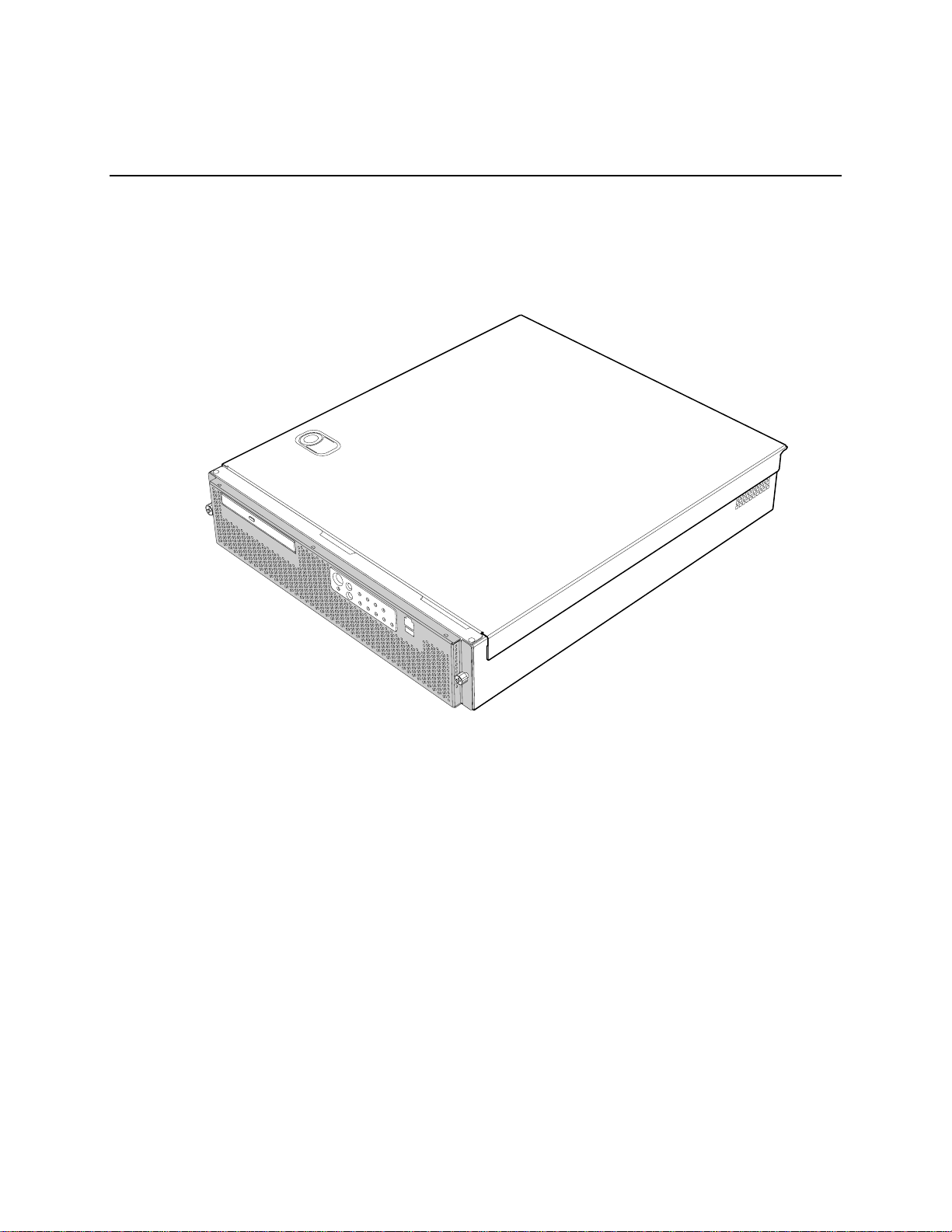
The Intel
®
Carrier Grade Server TIGI2U is shown in the following diagram.
16
Figure 1. Intel® Carrier Grade Server TIGI2U
®
Carrier Grade Server TIGI2U User Guide
Intel
TP01642
Page 17

Server Platform Features
Table 1 summarizes the major features of the server platform.
Table 1. Server Platform Features
Feature Description
Processors Support for up to two Intel® Xeon™ processors with an 800 MT/s MHz front side
bus at frequency 3.2 GHz with 2MB cache.
Memory
Chipset Intel® E7520 chipset, including:
Memory mirroring and memory sparing options
Six DIMM slots supporting DDR-2 400MHz memory
E7520 MCH
PXH
Intel® 82801ER I/O Controller Hub 5-R (ICH-5R)
I/O Control External connections:
Stacked PS/2 ports for keyboard and mouse
RJ45 Serial B port
Two RJ45 NIC connectors for 10/100/1000 Mb connections
Two rear USB 2.0 ports
One front USB port - USB 2.0 compliant with less than ten feet of
external cable
U320 high-density 80-pin SCSI connector (channel B)
Internal connections:
Two USB port headers, each of which supports two USB 2.0 ports
One DH10 Serial A header
One Ultra320 80-pin SCSI connector (Channel A)
One ATA-100 connector
SSI-compliant 34-pin, high-density 100-pin, and alternate 50-pin control
panel headers
Intel® Management Module 120-pin connector, supporting the
Professional and Advanced server management modules
Add-in Card
One low-profile riser slot that supports a riser card capable of supporting
upto three low-profile PCI-X 64/100MHz add-in cards.
One full-height riser slot, utilizing Intel® Adaptive Slot technology. Capable
of supporting riser cards that follows PCI-X specifications. The riser card
can support up to three full-height, full-length PCI-X 64/100 MHz add-in
cards.
Video On-board ATI* RAGE XL video controller with 8MB SDRAM
®
Carrier Grade Server TIGI2U User Guide
Intel
Continued
17
Page 18

Server Platform Features
Feature Description
Hard Drive SCSI support:
LAN Dual Intel® 82546GB 10/100/1000 NICs
Fans
Server Management /
Diagnostics
Server Management
Dual-channel LSI Logic* 53C1030 Ultra320 SCSI controller
⎯ Implements LSI Logic* Fusion-MPT architecture
⎯ Supports LSI Logic* Integrated Mirroring and Striping technology
Zero-channel RAID supporting the RUBI-2 specification
Two 80mm x 38mm fans
Two 40mm x 28mm fans
On-board Platform Instrumentation using the National Semiconductor*
PC87431M mini-Baseboard Management Controller (mBMC) (Default).
Support for optional Intel® Management Module - Advanced Edition or
Professional Edition
Support for Intel® Server Management 8.x
Intel® Light-Guided Diagnostics on all field replaceable units (F RUs)
®
Server Management 5.8 support
Intel
Telco Alarm Manager (TAM)
18
®
Carrier Grade Server TIGI2U User Guide
Intel
Page 19
Server Platform Features
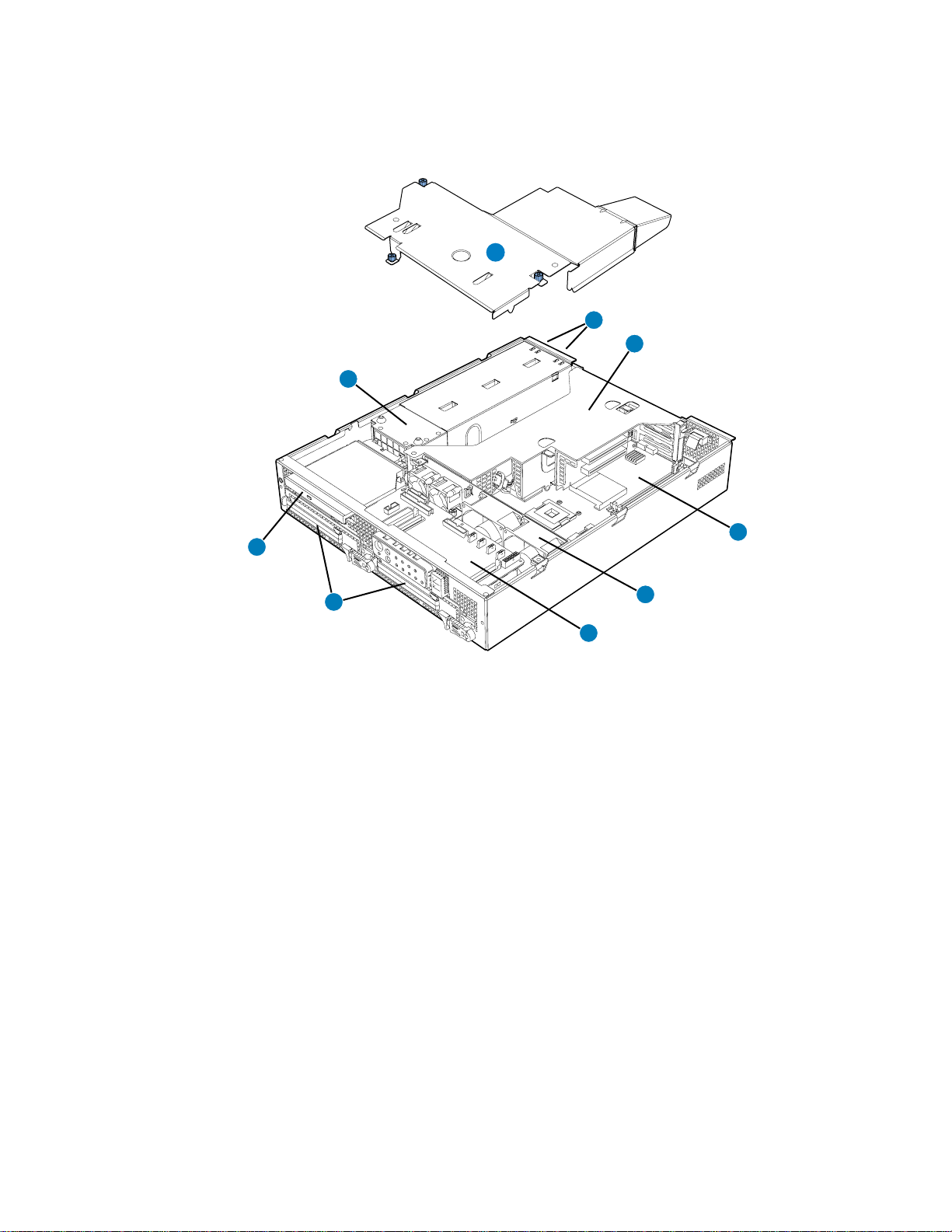
Server Platform Components
B
A
C
D
I
E
H
F
G
TP01643
A. Power Distribution Board F. System Fans
B. Processor Air Duct G. Front Panel I/O Board
C. Power Supplies H. SCSI Hard Disk Drive Carriers
D. PCI Riser Card Assembly I. Peripheral Bay (CD-ROM or DVD-ROM drive)
®
E. Intel
Server Board SE7520JR2
Figure 2. System Components
®
Carrier Grade Server TIGI2U User Guide
Intel
19
Page 20
Server Platform Features
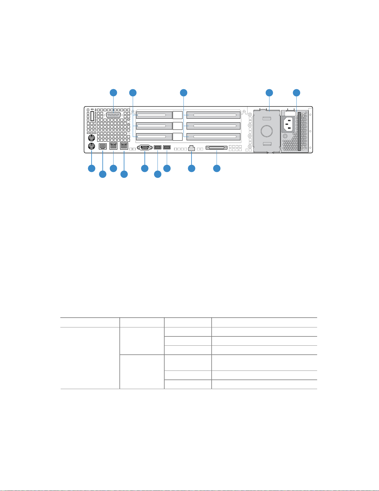
Server Platform Back Panel
A
F J
H
G
B C D
I
K
L
M N
A DB15 Alarms Connector H RJ45 NIC 1 Connector
B PCI Card Bracket (low-profile) I RJ45 NIC 2 Connector
C PCI Card Bracket (full-height) J Video Connector
D Optional second power supply or filler
panel (filler panel shown)
E Power Supply L USB 0
F PS/2 Mouse and Keyb oard Connectors M Server Management Port
G Rear Serial Port N SCSI Channel B
Figure 3. Platform Back
K USB 1
E
TP01644
The NIC LEDs at the right and left of each NIC provide the following information.
Table 2. NIC LEDs
NIC LED Color LED State Description
Off No network connection
Solid Amber Network connection in place
Blinking Amber Transmit/receive activity
Off 10 Mbps connection (if left LED is on or
blinking)
Solid Amber 100 Mbps connection
Solid Green 1000 Mbps connection
®
Carrier Grade Server TIGI2U User Guide
Intel
20
NIC1 / NIC2
(Gigabit)
Left LED
Right LED
Page 21
Server Platform Features
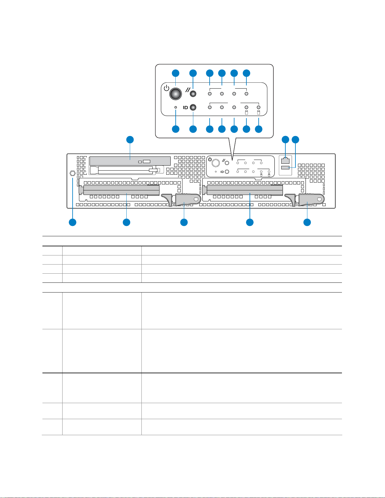
Server Platform Front Panel
A
G
N
Q
R
S
C ED F
B
CRT MNR PWRMJR
ID ONNIC
H
I
Alarms
Status
J
K M
1 0
L
Alarms
CRT MNR PWRMJR
Status
ID ONNIC
1 0
T U
O
P
TP01645
Front Panel Buttons
A Power button Toggles the system power
B Reset button Resets the system
G NMI button Assert NMI to baseboard
H ID button Toggles system ID LED
Front Panel LEDs
C Critical (amber ) When continuously lit, indicates the presence of a Critical System Fault. A
critical system fault is an error or event that is detected by the system with a
fatal impact to the system. In this case, the system cannot continue to
operate. An example is the loss of a large section of memory that renders the
system not operational. The front panel critical alarm relay will be engaged.
D Major (amber) When continuously lit, indicates the presence of a Major System Fault. A
major system fault is an error or event that is detected by the system that has
discernable impact to system operation. In this case, the system can continue
to operate but in a “degraded” fashion (reduced performance or loss of nonfatal feature reduction). An example is the loss of one of two mirrored disks.
The front panel major alarm relay will be engaged.
E Minor (amber) When continuously lit, indicates the presence of a Minor System Fault. A
minor system fault is an error or event that is detected by the system but has
little impact on actual system operation. An example is a correctable ECC
error. The front panel minor alarm relay will be engaged.
F Power (amber) When continuously lit, indicates the presence of a Power System Fault. The
front panel power alarm relay will be engaged.
I System ID LED (white) Continuously lit when activated either by a software command or by the front
panel ID button.
®
Carrier Grade Server TIGI2U User Guide
Intel
continued
21
Page 22
Server Platform Features
J NIC activity LED (green) Indicates activity on either NIC.
K Main power LED (green) When continuously lit, indicates the presence of DC power in the server. The
LED goes out when the power is turned off or if the power source is
disrupted.
L Disk 1 Activity/Fault LED
(green/amber)
M Disk 0 Activity/Fault LED
(green/amber)
Front of Server Platform
N Optional CD-ROM or DVD-ROM Drive
O Serial B via RJ45
P USB 2
Q Anti-static Connection
R Drive Carrier 0
S Drive Release Lever
T Drive Carrier 1
U Drive Release Lever
Indicates disk 1 SCSI hard drive activity when green, or a disk 1 SCSI hard
drive fault when amber.
Indicates disk 0 SCSI hard drive activity when green, or a disk 0 SCSI hard
drive fault when amber.
Figure 4. Front of Server Platform
Server Platform Peripherals
The platform provides for a peripheral location to install either a CD-ROM or a DVD-ROM
drive. The platform comes with a CD-ROM drive installed. For information on replacing the
CD-ROM drive, see “
Replacing the CD-ROM Drive”.
TP01647
Figure 5. Optional Peripheral CD-ROM or DVD-ROM Drive
22
®
Carrier Grade Server TIGI2U User Guide
Intel
Page 23
Server Platform Features
Server Board Connector and Component Locations
BA CD E
R
Q
P
O
F
N
M
L
K
J
A. SCSI Channel B J. Fan board connector
B. Battery K. Secondary IDE channel
C. Full-height riser slot
D. Low-profile riser slot
E. Back panel I/O ports
F. DIMM sockets
G. Processor socket 1
H. Processor socket 2
I. +12V processor power R. 120-pin connector for Intel® Management Module
L. 24-pin SSI power connector
M. 50-pin control panel connector
N. Power supply signal cable
O. USB header (1 x 10)
P. IDE power connector
Q. SCSI channel A
GHI
TP01646
Figure 6. Intel® Server Platform TIGI2U Board Diagram
®
Carrier Grade Server TIGI2U User Guide
Intel
23
Page 24

Server Platform Features
Configuration Jumpers
J1H2
C
B
A
1-2: Default
32
A1-A2: CMOS Clear by BMC
A2-A3: CMOS Clear Force Erase
B1-B2: Recovery Boot Disable (Normal Boot)
B2-B3: Recovery Boot Enable
C1-C2: Password Clear Protect
C2-C3: Password Clear Erase
Figure 7. Configuration Jumper Location
Table 3. Configuration Jumper [J1H2]
Jumper Name Pins What happens at system reset…
1-2 These pins should be jumpered for normal system operation. Password Clear
(line “A” in figure
above)
(line “B” in figure
above)
“C” in figure
above)
2-3 If these pins are jumpered, administrator and user passwords will be cleared on the
next reset. These pins should not be jumpered for normal operation.
1-2 These pins should be jumpered for normal system operation. Recovery Boot
2-3 If these pins are jumpered, the system will attempt to recover the BIOS by loading the
BIOS code into the flash device from a floppy disk. This jumper is typically used when
the BIOS has become corrupted. These pins should not be jumpered for normal
operation.
1-2 These pins should be jumpered for normal system operation. CMOS Clear (line
2-3 If these pins are jumpered, the CMOS settings will be cleared on the next reset.
These pins should not be jumpered for normal operation.
TP01652
24
®
Carrier Grade Server TIGI2U User Guide
Intel
Page 25
Server Platform Features
Front Panel IO (FPIO) System Board
Features
The TIGI2U server system has the following FPIO features:
• Four switches to control power-on, reset, NMI, and the system ID LED
• One system ID LED that can be controlled remotely or by the system ID switch
• Two system activity LEDs that indicate power-on and NIC activity
• Two hard drive activity/fault LEDS that indicate activity/fault status for drives 1 and 2
• Four system fault LEDs that indicate critical, major, minor, and power system fault
status
• Four system fault relays for external critical, major, minor, and power fault indicators
• One SCSI bus with hot-swap circuitry for controlling hot-swap SCSI disk drives 1 and 2
• IDE Bus from IDE Connector to blind mate connector
• One blind mate connector for interfacing to CDROM or floppy drive carrier assembly
• Connectors for interfacing to the power supply, server baseboard, drive carrier
assemblies, and hot plug disk drives 1 and 2
FPIO SCSI Subsystem Status LEDs
The status LEDs give the user a visual indication of the drives’ condition. There is a single
LED for each drive. The LEDs are bi-colored and use a combination of color and blinking
frequency to indicate multiple conditions. The LEDs are mounted on the FPIO board, and
the light is directed to the front panel through the use of a light pipe assembly. See
4
for LED activity definitions. See the Firmware EPS for definitions of the different blink
rates.
Table 4. LED Activity Definitions
LED State Drive Active Fault Condition
Solid Green
Blinking Green X
Blinking
Yellow/Green
Blinking
Yellow/Blank
Blank
X
X
Table
®
Carrier Grade Server TIGI2U User Guide
Intel
25
Page 26
Server Platform Features
Peripheral Bay
One peripheral drive (either a slim-line CD-ROM drive or a slim-line DVD-ROM drive) can
be mounted in the system using a blind-mate peripheral drive carrier inserted into the
peripheral drive bay. The peripheral drive bay is located above the hard drive tray and to
the left.
Hard Disk Drives
The platform ships with two drive carriers for mounting hot swap Ultra320 SCSI hard disk
drives in the chassis.
For information on how to install these drives, see “
Installing or Removing a Hard Drive”.
NOTE
The Intel® Carrier Grade Server TIGI2U does not support all SCSI
hard drives. For a list of validated hard drive manufacturers and hard
drive types, see
http://support.intel.com/support/motherboards/server/TIGI2U
Drives can consume up to 17 watts of power each. Drives must be
specified to run at a maximum ambient temperature of 45 °C.
Interconnect System (SysCon) Board
The interface board is used in the CD-ROM drive carrier assembly as the signal and
power interface between the CD-ROM drive and the FPIO system board. The interface
board has standard IDE and power connectors for interfacing to the CD-ROM drive, and
has a high-density blind-mate connector for interfacing to the FPIO system board.
26
TP01691
Figure 8. SysCon Board
®
Carrier Grade Server TIGI2U User Guide
Intel
Page 27
Server Platform Features
Power Supply
The power supply cage supports up to two hot-swap power supplies (either AC input or
DC input) in a (1+1) redundant configuration. A power supply filler module for the empty
power supply site is supplied for systems without redundancy. Only the DC input version
is NEBS certified.
The power subsystem supports the implementation of remote management features
including remote enable, which permits power to be activated from a variety of sources.
The power supply is rated for 600 watts of power at the following voltages.
AC Power Supply:
PARAMETER MIN RATED MAX Max Input Current
DC Voltage -38 VDC -48VDC/ -60VDC -75VDC 20.5ADC
DC Power Supply:
PARAMETER MIN RATED MAX
Start-up
Vac
Power
Off
Vac
Max Input
AC Current
Max Rated
Input AC
Current
Line Voltage
(110)
Line Voltage
(220)
Frequency 47 Hz 50/60Hz 63 Hz
90V
180V
rms
rms
100-127 V
200-240 V
rms
rms
140V
264V
85Vac
rms
±4Vac
- -
rms
75Vac
±5Vac
Notes:
1. Maximum input current at low input voltage range shall be measured at 90Vac,
at max load.
2. Maximum input current at high input voltage range shall be measured at
180VAC, at max load.
3. This is not to be used for determining agency input current markings.
4. Maximum rated input current is measured at 100VAC and 200VAC
10.0
A
rms
5.0 A
1,3
rms
2,3
8.9A
4.5A
rms
rms
4
4
®
Carrier Grade Server TIGI2U User Guide
Intel
27
Page 28

Server Platform Features
System Cooling
All system components except the power supply cage are cooled by a set of fans mounted
near the middle of the chassis and behind the hard drive bays. The TIGI2U system comes
in a non-redundant, four-fan configuration that consists of two 80mm x 38mm fans and two
40mm x 28mm fans.
Air flows in through the front bezel over the peripheral bay and the hard drive bays,
passes through the fans and over the baseboard, and exhausts through the rear of the
chassis. Each fan provides tachometer signal output to the server baseboard to indicate a
fan failure.
The cooling subsystem contains a fan array consisting of two 80 x 38 mm fans and two 40
x 28 mm fans to cool the server board and other components. A fan failure is indicated by
one of the fault LEDs located on the front panel.
Hardware Requirements
To avoid integration difficulties and possible board damage, your system must meet the
requirements outlined below. For a list of qualified components, see the links under
“
Additional Information and Software.”
Processor
The server board accommodates two Intel® Xeon™ 3.2 GHz processors operating at 800
MHz FSB with 2MB cache.
28
®
Carrier Grade Server TIGI2U User Guide
Intel
Page 29

Server Platform Features
Memory
The Server Board SE7520JR2 provides six DIMM sockets across two channels, Channel
A and Channel B. Channel A consists of DIMM sockets 1A, 2A, and 3A. Channel B
consists of DIMM sockets 1B, 2B, and 3B.
If six DIMMs are installed, the following maximum capacitites are possible:
For DDR-2 400: Maximum capacity of 16 GB
A minimum of one 256MB DIMM is required in DIMM socket 1A or 1B. This uses singlechannel interleave. However, for dual-channel interleave, providing optimum performance,
a minimum of two DIMMs should be installed in DIMM sockets 1A and 1B. Except for the
option of installing a single DIMM in socket 1A or 1B, DIMMs must be installed in pairs and
populated as follows:
DIMM1A and DIMM 1B: Populate these two sockets together first
DIMM 2A and DIMM 2B: Populate these sockets in addition to DIMM 1A and DIMM 2A
if four DIMMs are to be used.
DIMM 3A and DIMM3B: Populate these sockets after DIMM 1A, DIMM1B, DIMM2A,
and DIMM2B have been populated.
DIMMs must meet the following requirements:
Use only DDR2-400 ECC, registered DDR DIMM modules
Use only DIMMs that comply with the DDR specifications.
Use only DIMMs with DIMM organization of x72 ECC
Use only 240pin DIMMs
NOTE
When using DDR2-400 DIMM technologies, a maximum of four loads per memory channel
is supported. When all DIMMs used in the system match this technology, a maximum of
four DIMMs can be populated. Refer to the Intel
Product Specification for additional information regarding the memory sub-system.
In determining your memory requirements, the need for memory sparing or memory
mirroring must be considered.
Memory Sparing and Mirroring
The Intel® E7520 chipset includes hardware that supports memory mirroring and memory
on-line sparing. Both memory mirroring and memory on-line sparing provide a way to
prevent data loss in case a DIMM fails.
With memory mirroring the system maintains two copies of all data in the memory
subsystem. If a DIMM fails, the data is not lost because the second copy of the data is
available from the mirrored DIMM in the opposite channel. The system will not fail due to
memory error unless both the primary and the mirrored copy of the data become corrupt at
the same time.
®
Server Board SE7520JR2 Technical
®
Carrier Grade Server TIGI2U User Guide
Intel
29
Page 30

Server Platform Features
In a mirrored system, the maximum usable memory is one-half of the installed memory,
with a minimum of four DIMMs installed. Since the data is duplicated across DIMMs, it
means that up to one-half of the installed DIMMs are actively in use at any one time. The
remaining DIMMs are used for mirroring.
Two methods for memory mirroring are available:
Four identical DIMMs are used in DIMM sockets 1A, 1B, 2A, and 2B.
⎯ If the DIMM in socket 1A fails, the DIMM in socket 2B takes over.
⎯ If the DIMM in socket 1B fails, the DIMM in socket 2A takes over.
Four DIMMs are used with identical single-ranked DIMMs in Banks 2 and 3. DIMMs in
sockets 1A and 1B must be dual-ranked and identical.
⎯ If the DIMM in socket 1A fails, the DIMM in socket 1B takes over.
⎯ If the DIMM in socket 2A fails, the DIMM in socket 3B takes over.
⎯ If the DIMM in socket 2B fails the DIMM in socket 3A takes over.
For memory on-line sparing, one DIMM per channel is used as the memory spare. The spare
DIMM is not available for use, but is kept in reserve. If a DIMM begins to fail, the content of the
failing DIMM is copied to the spare DIMM in that channel. When all of the data is copied to the
spare DIMM, the primary DIMM is removed from service and the spare DIMM takes its place.
When memory on-line sparing is used, the spare DIMMs must be equal to or larger than the
largest in-service DIMM in that channel.
NOTE
Memory mirroring and memory sparing are mutually exclusive. Only
one can be active at a time. Refer to the Intel
SE7520JR2 Technical Product Specification for additional information
regarding the memory sub-system.
All memory components and DIMMs used with the Intel
must comply with the DDR specifications. For a complete list of supported memory
DIMMs, see the links under “
Additional Information and Software.”
®
Server Board
®
Carrier Grade Server TIGI2U
30
®
Carrier Grade Server TIGI2U User Guide
Intel
Page 31

Server Platform Features
NOTES
Although the server board architecture allows the user to mix various
sizes of DIMMs between channels, DIMMs must be identical within
each bank.
To be fully compliant with all applicable DDR SDRAM memory
specifications, the board should be populated with DIMMs that
support the Serial Presence Detect (SPD) data structure. This allows
the BIOS to read the SPD data and program the chipset to accurately
configure memory settings for optimum performance. If non-SPD
memory is installed, the BIOS will attempt to correctly configure the
memory settings, but performance and reliability may be impacted or
the DIMMs may not function under the determined frequency.
For ECC functionality, all installed DIMMs must be ECC.
®
Carrier Grade Server TIGI2U User Guide
Intel
31
Page 32

Page 33

Platform Installations and Upgrades
Platform Installations and Upgrades
Before You Begin
Before working with your server product, pay close attention to the safety instructions at
the beginning of this manual. See “
Tools and Supplies Needed
Phillips* (cross head) screwdriver (#1 bit and #2 bit)
Needle nosed pliers
Antistatic wrist strap and conductive foam pad (recommended). To mitigate damage
to equipment from static electricity discharge an antistatic wriststrap connected to
earth ground must be worn be service personnel.
Safety Information.”
System References
All references to left, right, front, top, and bottom are based on the reader facing the front
of the platform as it would be positioned for normal operation.
Cable Routing Reference
It is important for cables to be connected correctly. The diagram below provides
information about the location of the cable connections. Use this diagram as a reference
when following the installation steps in this chapter.
Intel® Carrier Grade Server TIGI2U User Guide 33
Page 34

Platform Installations and Upgrades
Connections
Front Panel I/O to CD-ROM
A
Front Panel I/O to HDD 2
B
Front Panel I/O to HDD 1
C
Power Supply to Front Panel I/O
D
Front Panel USB
E
IDE
F
Aux. Power
G
Front Panel
H
Main Power
I
Power to PCI Riser
J
CPU Power
K
Fan Module Monitor
L
Telco Alarms - back panel
M
SCSI
N
Individual Fan Power
O
Cable Legend
BLUE indicates Data Cable
RED indicates Power Cable
RED/BLUE indicates
Power and Data Cable
3
System Components
Power Supply
1
Power Distribution Module
2
CD-ROM Module
3
SCSI Hard Drive
4
Front Panel I/O Board
5
Fan Module
6
Server Board
7
1
G
2
H
I
A
D
F
E
J
7
K
L
M
6
34
4
B
N
O
5
4
C
TP01668
Figure 9. System Cable Routing
®
Carrier Grade Server TIGI2U User Guide
Intel
Page 35

Platform Installations and Upgrades
Removing and Installing the Chassis Cover
Removing the Chassis Cover
The Intel® Carrier Grade Server TIGI2U must be operated with the top cover in place to
ensure proper cooling. You will need to remove the top cover to add or replace
components inside of the platform. Before removing the top cover, power down the server
system and unplug all peripheral devices and the AC power cable or disconnect the DC
mains. None of the components inside the platform are hot-swappable.
To mitigate damage to equipment from static electricity discharge an antistatic wriststrap
connected to earth ground must be worn be service personnel.
NOTE
A nonskid surface or a stop behind the platform may be needed to
prevent the platform from sliding on your work surface.
1. Observe the safety and ESD precautions at the beginning of this section.
2. Turn off all peripheral devices connected to the server. Turn off the server.
3. Disconnect the AC power cord or disconnect the DC mains.
4. While holding the blue button at the top of the chassis in (see letter “A”), slide the top
cover back until it stops (see letter “B”).
5. Lift the cover straight up to remove it from the platform.
A
B
TP01648
Figure 10. Removing the Chassis Cover
®
Carrier Grade Server TIGI2U User Guide 35
Intel
Page 36

Platform Installations and Upgrades
Installing the Chassis Cover
1. Place the cover over the chassis so that the side edges of the cover sit just inside the
chassis sidewalls, with the front of the cover with about 1/8-inch gap showing between
the chassis cover and the sheet-metal at the front of the chassis.
2. Press down slightly on the chassis cover behind the CD-ROM / DVD-ROM drive area
and slide the cover forward until it clicks into place (see letter “A”).
3. Reconnect all peripheral devices and the AC power cord or the DC mains.
A
TP01649
Figure 11. Installing the Chassis Cover
36
®
Carrier Grade Server TIGI2U User Guide
Intel
Page 37

Platform Installations and Upgrades
Removing and Installing the Front Bezel
The front bezel needs to be removed only to install or remove hot-swap hard drives or the
CDROM drive.
Removing the Front Bezel
1. Loosen the captive screws at the left and right edges of the front bezel (one screw at
the right and one screw at the left; see letter “A”).
NOTE
Hold the bezel in place while you loosen the screws. After both
screws are loosened, the bezel will drop from the chassis.
2. Remove the front bezel from the chassis (see letter “B”).
A
B
A
TP01650
Figure 12. Removing the Front Bezel
®
Carrier Grade Server TIGI2U User Guide 37
Intel
Page 38

Platform Installations and Upgrades
Installing the Front Bezel
1. While holding the front bezel in place (see letter “A”), tighten the captive screws at the
left and right edges of the bezel (see letter “B”).
B
A
B
Figure 13. Installing the Front Bezel
TP01651
38
®
Carrier Grade Server TIGI2U User Guide
Intel
Page 39

Platform Installations and Upgrades
Removing and Installing the Processor Air Duct
The air duct must be removed to access the processor assembly and the four-fan
assembly. The processor air duct is required for proper airflow within the chassis. Be sure
the air duct is in place before installing the chassis cover.
Removing the Processor Air Duct
1. Power down the server system and unplug all peripheral devices and the AC power
cable or the DC mains.
2. Remove the chassis cover. For instructions, see “
3. Remove the screws at the top of the air duct (see letter “A”).
4. Lift the air duct from the server platform (see letter “B”).
Removing the Chassis Cover.”
A
B
Figure 14. Removing the Processor Air Duct
TP01670
®
Carrier Grade Server TIGI2U User Guide 39
Intel
Page 40

Platform Installations and Upgrades
Installing the Processor Air Duct
1. Place the processor air duct over the processor socket and four-fan assembly, using
caution to make sure you do not pinch any wires beneath the edges of the air duct
(see letter “A”).
2. Tighten the screws at the top of the air duct (see letter “B”). The top of the installed air
duct should be flush with the top surface of PCI adapter assembly.
3. Replace the chassis cover if you have completed all work inside of the chassis. For
instructions, see “
Installing the Chassis Cover.”
B
A
TP01671
Figure 15. Installing the Processor Air Duct
40
®
Carrier Grade Server TIGI2U User Guide
Intel
Page 41

Platform Installations and Upgrades
Installing and Removing Memory DIMMs
The silkscreen on the board for the DIMMs displays DIMM1B, DIMM1A, DIMM2B,
DIMM2A, DIMM3B and DIMM3A, starting from the outside of the board. DIMM1B is the
socket closest to the outside edge of the server board.
Installing DIMMs
To install DIMMs, follow these steps:
1. Power down the server system and unplug all peripheral devices and the AC power
cable or the DC mains.
2. Remove the chassis cover. For instructions, see “
3. Locate the DIMM sockets. See below.
Removing the Chassis Cover.”
DIMM 2A
DIMM 3B
DIMM 3A
DIMM 2B
DIMM 1A
DIMM 1B
TP01661
Figure 16. Installing Memory DIMMs
4. Push the clips at each end of the DIMM socket(s) outward to the open position. See
Figure 16.
5. Holding the DIMM by the edges, remove it from its anti-static package.
6. Position the DIMM above the socket. Align the small notch in the bottom edge of the
DIMM with the keys in the socket.
7. Insert the bottom edge of the DIMM into the socket.
8. Push down on the top edge of the DIMM until the retaining clips snap into place. Make
sure the clips are firmly in place.
®
Carrier Grade Server TIGI2U User Guide 41
Intel
Page 42

Platform Installations and Upgrades
9. Replace the chassis cover if you have completed all work inside of the platform. For
instructions, see “
Installing the Chassis Cover.”
Removing DIMMs
To remove a DIMM, follow these steps:
1. Power down the server system and unplug all peripheral devices and the AC power
cable or the DC mains.
2. Remove the chassis cover. For instructions, see “
3. Locate the DIMM(s). See
Figure 16.
4. Push the clips at each end of the DIMM socket(s) outward to the open position. The
DIMM lifts from the socket.
5. Holding the DIMM by the edges, lift it away from the socket, and store it in an antistatic package.
6. Replace the chassis cover if you have completed all work inside of the platform. For
instructions, see “
Installing the Chassis Cover.”
Removing the Chassis Cover.”
Replacing the Processor
NOTE
Use the instructions provided below to replace a processor instead of
using the instructions that came with the processor.
CAUTIONS
Processor must be appropriate: You may damage the server board
if you install a processor that is inappropriate for your server. See
“
Additional Information and Software” for a link to the list of compatible
processors.
ESD and handling processors: Reduce the risk of electrostatic
discharge (ESD) damage to the processor by doing the following:
(1) Touch the metal chassis before touching the processor or server
board. Keep part of your body in contact with the metal chassis to
dissipate the static charge while handling the processor. (2) Avoid
moving around unnecessarily.
Follow the instructions below to remove and then install a processor.
42
®
Carrier Grade Server TIGI2U User Guide
Intel
Page 43

Platform Installations and Upgrades
Removing the Processor
1. Power down the server system and unplug all peripheral devices and the AC power
cable or the DC mains.
2. Remove the chassis cover. For instructions, see “
3. Remove the processor air duct that covers the processor. For instructions, see
Removing the Processor Air Duct.”
“
4. Loosen the four captive screws on the corners of the heat sink.
Removing the Chassis Cover.”
TP01660
Figure 17. Removing Heat Sink
5. Twist the heat sink slightly to break the seal between the heat sink and the processor.
6. Lift the heat sink from the processor. If it does not pull up easily, twist the heat sink
again. Do not force the heat sink from the processor. Doing so could damage the
processor.
7. Lift the processor lever.
8. Remove the processor.
®
Carrier Grade Server TIGI2U User Guide 43
Intel
Page 44

Platform Installations and Upgrades
Installing the Processor
To install a processor, follow these instructions:
1. Power down the server system and unplug all peripheral devices and the AC power
cable or the DC mains.
2. Remove the chassis cover. For instructions, see “
3. Remove the processor air duct that covers the processor. For instructions, see
Removing the Processor Air Duct.”
“
4. Locate the processor socket and raise the socket handle completely. See
Figure 18. Open the Processor Socket Lever
Removing the Chassis Cover.”
TP01656
Figure 18.
5. Aligning the pins of the processor with the socket (see letter “A”), insert the processor
into the socket (see letter “B”). See
Figure 19.
A
B
A
44
TP01657
Figure 19. Installing the Processor in the Processor Socket
®
Carrier Grade Server TIGI2U User Guide
Intel
Page 45

Platform Installations and Upgrades
6. Close the handle completely. See Figure 20.
TP01658
Figure 20. Close Processor Socket Lever
6. The heat sink has Thermal Interface Material (TIM) located on the bottom of it. If the
TIM has a covering sheet on it, remove the covering sheet.
7. Set the heat sink over the processor, lining up the four captive screws with the four
posts surrounding the processor. Use caution and make sure that cables are not
pinched beneath the heat sink.
8. Loosely screw in the captive screws on the heat sink corners in a diagonal manner. Do
no fully tighten one screw before tightening another.
9. Gradually and equally tighten each captive screw until each is firmly tightened.
TP01659
Figure 21. Installing Heat Sink
10. Install the processor air duct. The air duct must be in place for proper system cooling.
For instructions, see “
®
Carrier Grade Server TIGI2U User Guide 45
Intel
Installing the Processor Air Duct.”
Page 46

Platform Installations and Upgrades
Installing or Removing a Hard Drive
Up to two hot-swappable SCSI drives can be installed in your chassis. It is not necessary
to remove the chassis cover to add or replace a hot-swap hard drive. It is necessary to
remove the front bezel from the chassis.
CAUTION
The Intel® Carrier Grade Server TIGI2U does not support all hard
drives. To see a list of validated manufacturers and hard drive
types, see:
http://support.intel.com/support/motherboards/server/TIGI2U
Installing a Hard Drive
1. Remove the front bezel. For instructions, see “Removing the Front Bezel.”
2. Press in on the green latch on the front of the hard drive carrier (see letter “A”).
3. Pull out on the black lever to slide the carrier from the chassis (see letter “B”).
A
B
TP01662
Figure 22. Removing Hard Drive Carrier from Chassis
4. Remove the hard drive from its wrapper and place it on an antistatic surface.
5. Set any jumpers and/or switches on the drive according to the drive manufacturer’s
instructions.
6. With the drive circuit-side down, position the connector end of the drive so that it is
facing the rear of the drive carrier (see letter “A”).
®
Carrier Grade Server TIGI2U User Guide
46
Intel
Page 47

Platform Installations and Upgrades
7. Align the holes in the drive to the holes in the drive carrier and attach it to the carrier
using four screws that meet the drive vendor’s recommendation (see letter “B”).
A
B
B
TP01663
Figure 23. Attaching a Hard Disk Drive to a Carrier
8. With the black lever in the fully open position, slide the drive assembly into the chassis.
Insert the primary drive in the right bay (see letter “A”). The green latch at the front of
the drive carrier must be to the right. Do not push on the black drive carrier lever until
the lever begins to close by itself.
9. When the black drive carrier lever begins to close by itself, push on it to lock the drive
assembly into place (see letter “B”).
B
A
TP01664
®
Carrier Grade Server TIGI2U User Guide 47
Intel
Page 48

Platform Installations and Upgrades
Figure 24. Inserting Hard Disk Drive Assembly into Chassis
10. Install the front bezel. Install the front bezel. For instructions, see “Installing the Front
Bezel
.”
Removing a Hard Drive
1. Remove the front bezel. For instructions, see “Removing the Front Bezel.”
2. Press in on the green latch at the front of the hard drive carrier.
3. Pull out on the black lever to slide the carrier from the chassis.
4. Remove the four screws that attach the hard drive to the drive carrier. Lift the drive
from the carrier. Store the drive in an anti-static bag.
5. (optional) Place the plastic retention device into the drive carrier, using the four screws
you removed from the hard drive.
6. Insert the screws that held the drive in the carrier into the screw locations on the
carrier.
7. With the black lever in the fully open position, slide the drive carrier into the chassis.
The green latch must be to the right. Do not push on the black lever until the lever
begins to close by itself.
8. When the black lever begins to close by itself, push on it to lock the drive carrier into
place.
9. Install the front bezel. For instructions, see “
Installing the Front Bezel.”
Replacing the CD-ROM Drive
Your Intel® Carrier Grade Server TIGI2U comes with a CD-ROM drive installed in it. As an
option, you can replace the CD-ROM drive with a DVD-ROM drive. It is necessary to
remove the chassis cover and the front bezel from the chassis to remove or replace the
drive.
The peripheral bay supports either a CD-ROM drive carrier assembly or a DVD-ROM drive
carrier assembly. Both the blind-mate CD-ROM drive carrier assembly and the blind-mate
DVD-ROM drive carrier assembly can be inserted or removed when the system power is
off. After the drive carrier assembly is installed into the system, a horizontal handle is
used to secure it to the chassis.
CAUTION
The CD-ROM / DVD-ROM drive is NOT hot-swappable. Before
removing or replacing the drive, you must first take the server out of
service, turn off all peripheral devices connected to the system, turn
off the system by pressing the power button, and unplug the AC
power cord from the system or wall outlet or disconnect the DC mains.
48
®
Carrier Grade Server TIGI2U User Guide
Intel
Page 49

Platform Installations and Upgrades
Removing the CD-ROM / DVD-ROM Drive
1. Power down the server system and unplug all peripheral devices and the AC power
cable or the DC mains.
2. Remove the chassis cover. For instructions, see “
3. Remove the front bezel. For instructions, see “
4. Pull out on the drive carrier handle (see letter “A”).
5. Slide the CD-ROM / DVD-ROM drive assembly from the chassis (see letter “B”).
6. Remove the srew at the left side of the drive assembly and save for future use.
B
Removing the Chassis Cover.”
Removing the Front Bezel.”
A
TP01665
Figure 25. Removing CD-ROM / DVD-ROM Drive Assembly from Chassis
®
Carrier Grade Server TIGI2U User Guide 49
Intel
Page 50

Platform Installations and Upgrades
Installing the CD-ROM / DVD-ROM Drive
1. Lining up the pins on each side of the bracket (two on each side) to the holes in the
drive, set the replacement CD-ROM or DVD-ROM drive into the drive bracket. You
may need to push gently on one side of the bracket to push the pins into place.
2. Install the screw at the left side of the drive assembly.
3. Slide the CD-ROM / DVD-ROM drive assembly into the chassis (see letter “A”).
4. With the black drive carrier handle in the fully open position, slide the drive assembly
into the chassis (see letter “B”).
5. Attach the drive power and data cables at the rear of the drive. When the cables are
firmly installed, the cable retention clips will lock into place.
A
B
Figure 26. Install CD-ROM Drive or DVD-ROM Drive Assembly into Chassis
6. Install the chassis cover. For instructions, see “
7. Install the front bezel. For instructions, see “
Removing the Chassis Cover.”
Installing the Front Bezel.”
TP01666
50
®
Carrier Grade Server TIGI2U User Guide
Intel
Page 51

Platform Installations and Upgrades
Installing or Removing a PCI Add-in Card
CAUTION
PCI cards in this system are NOT hot swappable. Before removing or
replacing the PCI card, you must first take the server out of service,
turn off all peripheral devices connected to the system, turn off the
system by pressing the power button, and unplug the AC power cord
from the system or wall outlet or disconnect the DC mains.
Installing a PCI Add-in Card
1. Power down the server system and unplug all peripheral devices and the AC power
cable or the DC mains.
2. Remove the chassis cover. For instructions, see “
3. Disconnect the power cable to the riser card assembly.
4. Lift blue tabs and pull up on the riser to remove the riser card assembly from the
chassis.
Removing the Chassis Cover.”
TP01683
Figure 27. Removing Riser Assembly from Chassis
®
Carrier Grade Server TIGI2U User Guide 51
Intel
Page 52

Platform Installations and Upgrades
5. Place riser assembly as shown.
• To install a low-profile PCI card (see
bar as shown (see letter “A”) and insert the card into one of the slots on the riser
connector (see letter “B”). Lock the tool-less retention bar into place.
• To install a full-height PCI card (see Figure 29): Insert the card into one of the
slots on the riser connector (see letter “A”) and screw the PCI card bracket into
place as shown (see letter “B”). Close the retention bar and lock it in place (see
letter “C”).
Figure 28): Unlock the tool-less retention
NOTE
When populating add-in cards, the add-in cards must be installed starting with the slot
furthest from the server board. For example, when using a three slot riser, a single add-in
card must be installed in the top PCI slot. A second add-in card must be installed in the
middle slot, and so on.
CAUTION
Press the riser card straight into the slot. Tipping it in the slot while
installing it may damage the riser card, board slot, or the PCI card.
A
B
Figure 28. Installing Low-Profile PCI Card into Riser
TP01685
52
®
Carrier Grade Server TIGI2U User Guide
Intel
Page 53

Platform Installations and Upgrades
C
Figure 29. Installing Full Length PCI Card into Riser
B
A
TP01695
6. Insert the PCI riser assembly into the chassis.
7. Install the chassis cover. For instructions, see “
Installing the Chassis Cover.”
Removing a PCI Add-in Card
1. Power down the server system and unplug all peripheral devices and the AC power
cable or the DC mains.
2. Remove the chassis cover. For instructions, see “
3. Disengage the power connector from the PCI riser card assembly.
4. Lift blue tabs and pull up on the riser to remove the PCI riser card assembly from the
chassis (see
Figure 27).
5. Place riser assembly as shown.
• To remove a low-profile PCI card (see Figure 30): Unlock the tool-less retention
bar as shown (see letter “A”) and pull the PCI card from the riser card slot (see
letter “B”).
• To remove a full-height PCI card (see
shown (see letter “A”). Unscrew the PCI card bracket (see letter “B”) and pull
the PCI card from the riser card slot (see letter “C”).
Removing the Chassis Cover.”
Figure 31): Unlock the retention bar as
®
Carrier Grade Server TIGI2U User Guide 53
Intel
Page 54

Platform Installations and Upgrades
A
B
Figure 30. Removing a Low-Profile PCI Card
A
TP01684
C
Figure 31. Removing a Full Height PCI Card
6. Insert the empty PCI riser assembly into the chassis.
7. Install the chassis cover. For instructions, see “Installing the Chassis Cover.”
B
TP01696
54
®
Carrier Grade Server TIGI2U User Guide
Intel
Page 55

Platform Installations and Upgrades
Replacing the Power Supply
CAUTION
Your server does not have a redundant power supply unless you have
purchased the optional second power supply. Before replacing the
power supply, you must first take the server out of service, turn off all
peripheral devices connected to the system, turn off the system by
pressing the power button, and unplug the AC power cord from the
system or wall outlet or disconnect the DC mains.
If you have a second power supply in your server, you can skip step
one in the instructions below.
Removing the Power Supply
1. Power down the server system and unplug all peripheral devices and the AC power
cable or the DC mains.
2. Depress and hold the green lever to disengage the power supply (see letter “A”).
3. Grasp the black handle and pull the power supply from the chassis (see letter “B”).
Figure 32. Removing the Power Supply
A
B
TP01653
®
Carrier Grade Server TIGI2U User Guide 55
Intel
Page 56

Platform Installations and Upgrades
Installing the Power Supply
1. When inserting the new power supply, make sure the green handle is depressed
downward while sliding the module into the power supply cage.
TP01654
Figure 33. Installing the Power Supply
2. Install the chassis cover. For instructions, see “Installing the Chassis Cover.”
DC Power In Male Connector Configuration
Please use the following instructions when installing or replacing a DC power supply.
1. Slide open top of male connector to reveal screw holes (see letter “A” in
2. Strip wire insulation as shown. Note minimum wire gauge (see letter “B” in
3. Insert each wire all the way and tighten to 24 in-lb (2.7 N-m) torque (see letter “C” in
Figure 34).
#2 Phillips*
Screwdriver
A
B
Min. Wire
14 AWG
Figure 34. DC Power In Male Connector Configuration
Strip Wire 0.625"
(16mm)
C
Figure 34).
Figure 34).
56
®
Carrier Grade Server TIGI2U User Guide
Intel
Page 57

Platform Installations and Upgrades
Grounding a DC Powered System
The DC chassis provides two #10-32 threaded studs for chassis enclosure grounding. A
single 90º standard barrel two-hole compression terminal lug with 5/8-inch pitch suitable
for #14-10 AWG conductor (such as the Thomas & Betts terminal lug p/n 256-31426-141)
must be used for proper safety grounding.
NOTE
A crimping tool may be needed to secure the terminal lug to the
grounding cable.
Figure 35 shows how the four #10-32 nuts connect to the 90º two-hole terminal lug.
Tighten each to 10 in-lb torque.
Figure 35. Connecting the Terminal Lug
Replacing the Four-Fan Assembly
CAUTION
Your server does not have hot-swappable fans. Before replacing any
of the fans, you must first take the server out of service, turn off all
peripheral devices connected to the system, turn off the system by
pressing the power button, and unplug the AC power cord from the
system or wall outlet or disconnect the DC mains.
®
Carrier Grade Server TIGI2U User Guide 57
Intel
Page 58

Platform Installations and Upgrades
Removing the Four-Fan Assembly
1. Power down the server system and unplug all peripheral devices and the AC power
cable or the DC mains.
2. Remove the chassis cover. For instructions, see “
3. Remove the processor air duct. For instructions, see “
Duct
.”
4. Disconnect the fan connectors from the front panel I/O board (see letter “A” in
36
).
5. Remove the captive screw that attaches the four-fan assembly to the chassis (see
letter “B” in
Figure 36).
6. Lift the fan module and remove it from the chassis (see letter “C” in
B
Removing the Chassis Cover.”
Removing the Processor Air
Figure 36).
Figure
C
Figure 36. Removing the Four-Fan Assembly
A
TP01672
58
®
Carrier Grade Server TIGI2U User Guide
Intel
Page 59

Platform Installations and Upgrades
Installing the Four-Fan Assembly
1. Lower the fan module into place (see letter “A”).
2. Tighten the captive screw (see letter “B”).
3. Connect the fan cables to the correct fan connectors on the front panel I/O board (see
letter “C”). The fan connectors are labeled on the front panel I/O board.
B
A
C
Figure 37. Installing the Four-Fan Assembly
®
Carrier Grade Server TIGI2U User Guide 59
Intel
TP01673
Page 60

Platform Installations and Upgrades
Replacing the Mini-Bezel
The mini bezel is installed over the front panel controls and LEDs. To replace the mini
bezel, use the following instructions. It is not necessary to power down the server to
replace the mini-bezel.
1. Remove the front bezel. For instructions, see “
2. Insert your thumb or a finger between the power button and the NIC / USB connectors
(see letter “A”). Do not press the power button.
3. Squeeze gently to the right while pulling out on the mini bezel (see letter “B”). The left
side of the bezel will disengage from the chassis.
4. Unhook the clip at the right of the mini-bezel.
5. Press the replacement bezel firmly into place, one side at a time.
6. While pressing in, move the mini bezel from left to right to make sure it is firmly seated.
7. Install the front bezel. For instructions, see “
Removing the Front Bezel.”
Installing the Front Bezel.”
A
B
TP01676
Figure 38. Removing the Mini Bezel
60
®
Carrier Grade Server TIGI2U User Guide
Intel
Page 61

Platform Installations and Upgrades
Replacing the Front Panel I/O Board
The Front Panel I/O Board provides an interface to the controls at the front of the server
system, the power interconnect for the server board, the USB2 and Serial B interface, and
the front panel LED interface connect. To replace the Front Panel I/O Board, the following
components must be removed:
All cable connections on the Front Panel I/O Board and selected connections from
other board / components
Processor Air Duct
Power supply
Power distribution board
Light pipe
Use the instructions below to remove the Front Panel I/O Board, remove and replace the
light pipe, and install a replacement front panel board.
CAUTION
Before replacing any of the server boards, you must first take the
server out of service, turn off all peripheral devices connected to the
system, turn off the system by pressing the power button, and unplug
the AC power cord from the system or wall outlet or disconnect the
DC mains.
Removing the Front Panel I/O Board
1. Power down the server system and unplug all peripheral devices and the AC power
cable or the DC mains.
2. Remove the chassis cover. For instructions, see “
3. Remove the power supply. For instructions, see “
4. Remove the processor air duct. For instructions, see “
”.
Duct
5. Remove the power interface board. For instructions, see “
Interface Board
6. Remove the four-fan assembly. For instructions, see “
Assembly
.”
.”
Removing the Chassis Cover.”
Removing the Power Supply.”
Removing the Processor Air
Removing the Power
Removing the Four-Fan
®
Carrier Grade Server TIGI2U User Guide 61
Intel
Page 62

Platform Installations and Upgrades
7. Disconnect the following cables on the Front Panel I/O Board:
Power interface board power from J1A1
CD-ROM / DVD-ROM data and power cables from the rear of the CD-ROM or
DVD-ROM drive
Front panel data from J5A1
HDD connector from J5A2
Front panel USB from J4B1
System fan control connector from J7A1
Fan connectors from J7A2, J8A1, J8A2 and J9A1
Telco Alarms cable from J9A2
SCSI channel from J5B1
SCSI flex 1 from J9D1
SCSI flex 2 from J5C1
8. Remove the screws near the blind-mate connector (J2A1) and the fan assembly
connector (J7A1).
9. Gently work the front panel I/O board backward (see letter “A” in
Figure 39), toward the
rear of the chassis to disengage the light pipe from behind the front mini-bezel.
10. Pull the front panel I/O board up over the placement pegs (see letter “B” in
and lift it from the chassis (see letter “C” in
Figure 39).
Figure 39)
B
A
Figure 39. Removing the Front Panel Board
C
TP01655
62
®
Carrier Grade Server TIGI2U User Guide
Intel
Page 63

Platform Installations and Upgrades
Replacing the Light Pipe
Light pipe replacement instructions are included as part of the instructions to replace the
front panel I/O board. To replace the light pipe using an existing front panel I/O board, use
the instructions under the following headings, replacing the existing front panel I/O board
instead of installing a replacement board:
“
Removing the Front Panel I/O Board”
“
Replacing the Light Pipe” (the steps below)
Installing the Front Panel I/O Board”
“
1. Note the position of the light pipes so that you will be able to correctly position it on the
Front Panel I/O Board during the re-installation process. The pipes extend outward
from the Front Panel I/O Board.
2. Remove the light pipe by gently pressing the four plastic clips from the underside of
the Front Panel I/O Board until the bottom of the clips are flush with the bottom of the
Front Panel I/O Board.
3. Gently ease the light pipe from the Front Panel I/O Board.
4. Insert the four plastic clips on the light pipe or the replacement light pipe into the
matching holes in the new Front Panel I/O Board. Insert the clips gently and evenly –
do not insert one clip fully without first partially pressing the others into place.
TP01667
Figure 40. Replacing the Light Pipe
®
Carrier Grade Server TIGI2U User Guide 63
Intel
Page 64

Platform Installations and Upgrades
Installing the Front Panel I/O Board
1. Lower the replacement Front Panel I/O Board into the chassis (see letter “A”).
2. While holding the rear edge of the board, ease the board forward, sliding the NIC
connector and USB port through the matching cutout at the front of the chassis.
3. Lower the rear of the board into position fitting the board over the placement pegs (see
letter “B”).
4. Push the board forward, locking the board onto the placement pegs (see letter “C”).
5. Replace the screws you removed previously, near the blind-mate connector (J2A1)
and the fan assembly connector (J7A1).
B
C
Figure 41. Inserting the Front Panel Board
A
TP01700
6. Install the power interface board. For instructions, see “Installing the Power Interface
.”
Board
7. Install the power supply. For instructions, see “
Installing the Power Supply.”
8. Reconnect all cables to the Front Panel I/O Board. Note that most connectors are
labeled to match the connection point on the boards.
64
®
Carrier Grade Server TIGI2U User Guide
Intel
Page 65

Platform Installations and Upgrades
B
A
C
D
G
E
F
TP01675
Figure 42. Cabling to Front Panel Board
A. Power
B. SCSI Channel B Cable
C. USB
D. Front Panel Connector
E. IDE Cable
F. Fan Connector Cable
G. Telco Alarms Cable
9. Install the chassis cover. For instructions, see “Installing the Chassis Cover.”
®
Carrier Grade Server TIGI2U User Guide 65
Intel
Page 66

Platform Installations and Upgrades
Replacing the PCI Riser Board
CAUTION
Before replacing any of the server boards, you must first take the
server out of service, turn off all peripheral devices connected to the
system, turn off the system by pressing the power button, and unplug
the AC power cord from the system or wall outlet or disconnect the
DC mains.
Use the following instructions to replace the PCI riser board.
1. Power down the server system and unplug all peripheral devices and the AC power
cable or the DC mains.
2. Remove the chassis cover. For instructions, see “
3. Disengage the power from the PCI riser assembly.
4. Remove the PCI card(s). For instructions, see “
5. Depress and hold the blue retention mechanism (see letter “A” in the figures below).
6. Slide the riser board over the placement peg(s) (see letter “B” the figures below) and
remove the riser board (see letter “C” in the figures below).
7. If replacing the full-height riser board, unplug the 5V power cable from the riser board
(see letter “D” in
Figure 44).
Removing the Chassis Cover.”
Removing a PCI Add-in Card.”
A
C
Figure 43. Removing the Low-Profile PCI Riser Board
B
TP01692
66
®
Carrier Grade Server TIGI2U User Guide
Intel
Page 67

Platform Installations and Upgrades
B
Figure 44. Removing the Full Height PCI Riser Board
A
D
C
TP01698
8. If replacing the full-height riser board, first plug the 5V power cable into the riser board
(see letter “A” in
Figure 46).
9. Depress and hold the blue retention mechanism (for low-profile riser board see letter
“A” in
Figure 45; for full-height riser board see letter “B” in Figure 46).
10. Put the replacement riser board over the placement peg(s) as shown (for low-profile
riser board see letter “B” in
) and slide gently to lock in place (for low-profile riser board see letter “C” in Figure
46
; for full-height riser board see letter “D” in Figure 46).
45
Figure 45; for full-height riser board see letter “C” in Figure
A
B
C
Figure 45. Installing the Low-Profile PCI Riser Board
®
Carrier Grade Server TIGI2U User Guide 67
Intel
TP01694
Page 68

Platform Installations and Upgrades
D
B
A
C
TP01697
Figure 46. Installing the Full Height PCI Riser Board
11. Install the PCI card(s). For instructions, see “
12. Install the chassis cover. For instructions, see “
Installing a PCI Add-in Card.”
Installing the Chassis Cover.”
Replacing the Power Interface Board
The power interface board routes power from the power supply to the rest of the server
system. To replace the power interface board, the PCI riser assembly and the power
supply must be removed. Use the following instructions to replace the power interface
board.
CAUTION
Before replacing any of the server boards, you must first take the
server out of service, turn off all peripheral devices connected to the
system, turn off the system by pressing the power button, and unplug
the AC power cord from the system or wall outlet or disconnect the
DC mains.
68
®
Carrier Grade Server TIGI2U User Guide
Intel
Page 69

Platform Installations and Upgrades
Removing the Power Interface Board
1. Power down the server system and unplug all peripheral devices and the AC power
cable or the DC mains.
2. Remove the chassis cover. For instructions, see “
3. Remove the PCI riser assembly. For instructions, see “
steps 3 – 4.
4. Remove the processor air duct. For instructions, see “
Duct
.”
5. Remove the peripheral bay drive. For instructions, see “
DVD-ROM Drive
.”
6. Remove the power supply. For instructions, see “
7. Disconnect all power cables from the power interface board.
8. Press down on the power interface retention lever (see letter “A”) and pull up to
release the power interface board from the placement pegs (see letter “B”).
9. Lift the power interface board from the chassis (see letter “C”).
Removing the Chassis Cover.”
Removing a PCI Add-in Card.”
Removing the Processor Air
Removing the CD-ROM /
Removing the Power Supply.”
C
A
B
TP01701
Figure 47. Removing the Power Interface Board
®
Carrier Grade Server TIGI2U User Guide 69
Intel
Page 70

Platform Installations and Upgrades
Installing the Power Interface Board
1. Press down on the power interface retention lever (see letter “A”) and lower the
replacement power interface board into place (see letter “B”).
2. Make sure that the power interface board is placed over the placement pegs and
gently push down (see letter “C”).
B
A
C
Figure 48. Installing the Power Interface Board
3. Connect all power cables.
4. Install the power supply. For instructions, see “
5. Install the peripheral bay drive. For instructions, see “
ROM Drive
.”
6. Install the processor air duct. For instructions, see “
7. Install the PCI riser assembly. For instructions, see “
8. Install the chassis cover. For instructions, see “
Installing the Power Supply.”
Installing the CD-ROM / DVD-
Installing the Processor Air Duct.”
Installing a PCI Add-in Card.”
Installing the Chassis Cover.”
Replacing the Serial/Alarms Cable
The Intel® Carrier Grade Server TIGI2U includes a serial/alarms cable. To replace the
serial/alarms cable, use the following instructions.
TP01702
70
®
Carrier Grade Server TIGI2U User Guide
Intel
Page 71

Platform Installations and Upgrades
Removing the Serial/Alarms Cable
1. Power down the server system and unplug all peripheral devices and the AC power
cable or the DC mains.
2. Remove the chassis cover. For instructions, see “
3. Remove the threaded standoffs as shown in
Removing the Chassis Cover.”
Figure 49.
Figure 49. Removing the Serial/Alarms Cable Threaded Standoffs
4. Remove the serial/alarms connector from the chassis.
Figure 50. Removing the Serial/Alarms Connector from the Chassis
TP01680
TP01679
®
Carrier Grade Server TIGI2U User Guide 71
Intel
Page 72

Platform Installations and Upgrades
Installing the Serial/Alarms Cable
1. Install the serial/alarms connector into the chassis. See
Figure 51.
Figure 51. Installing the Serial/Alarms Connector into Chassis
2. Install the threaded standoffs as shown in Figure 52.
Figure 52. Installing the Serial/Alarms Cable Threaded Standoffs
TP01681
TP01682
72
®
Carrier Grade Server TIGI2U User Guide
Intel
Page 73

Platform Installations and Upgrades
Replacing the Server Board
The Intel® Carrier Grade Server TIGI2U uses the Intel® Server Board SE7520JR2. To
replace the server board, the following components must be removed:
All cable connections on the server board
Heat sink(s)
Processor(s)
All DIMMs
PCI riser assembly
Four-fan assembly
To replace the server board, use the following instructions.
CAUTION
Before replacing any of the server boards, you must first take the
server out of service, turn off all peripheral devices connected to the
system, turn off the system by pressing the power button, and unplug
the AC power cord from the system or wall outlet or disconnect the
DC mains.
Removing the Server Board
1. Power down the server system and unplug all peripheral devices and the AC power
cable or the DC mains.
2. Remove the chassis cover. For instructions, see “
3. Remove the PCI riser assembly. For instructions, see “
steps 3 – 4.
4. Remove the processor air duct. For instructions, see “
.”
Duct
5. Remove all DIMMs. For instructions, see “
6. Remove the heat sink and processor. For instructions, see “
7. Remove the four-fan assembly. For instructions, see “
Assembly
8. Disconnect all cables from the server board.
9. Remove the eight screws that attach the server board to the chassis.
10. Lift the server board from the chassis. Use caution in pulling it out from beneath the
Serial B connector at the rear of the chassis.
.”
Removing DIMMs.”
Removing the Chassis Cover.”
Removing a PCI Add-in Card,”
Removing the Processor Air
Removing the Processor.”
Removing the Four-Fan
®
Carrier Grade Server TIGI2U User Guide 73
Intel
Page 74

Platform Installations and Upgrades
A
C
B
Figure 53. Removing the Server Board
TP01674
74
®
Carrier Grade Server TIGI2U User Guide
Intel
Page 75

Platform Installations and Upgrades
Installing the Server Board
1. If you have a SCSI cable to connect, do this first before installing the server board (see
letter “A” in the figure below).
2. Set the replacement board into place (see letter “B” in the figure below), using caution
to make sure no cables are pinched under the board. Insert the rear edge of the board
first, and line up the I/O ports at the rear of the system.
3. Make sure the standoff locations line up correctly and reinsert the eight screws
removed in step 9, under “
below.
A
Removing the Server Board.” See letter “D” in the figure
B
D
C
TP01689
Figure 54. Installing the Server Board
®
Carrier Grade Server TIGI2U User Guide 75
Intel
Page 76

Platform Installations and Upgrades
4. Connect all cables to the server board.
Note:
If you forgot to install your SCSI cable prior to installing the server board, or
you need to replace the SCSI cable without replacing the server board, secure
the SCSI cable to the board connector and make sure it is fully seated with a
#2 flat-blade screwdriver, as shown in the figure below.
TP01690
Figure 55. Securing SCSI Cable to Server Board Connector
5. Install the four-fan assembly. For instructions, see “
6. Install the processor and heat sink. For instructions, see “
7. Install all DIMMs. For instructions, see “
Installing DIMMs.”
Installing the Four-Fan Assembly.”
Installing the Processor.”
8. Push the handle on the front panel to baseboard connector towards the rear of the
chassis.
9. Install the processor air duct. For instructions, see “
10. Install the PCI riser assembly. For instructions, see “
11. Install the chassis cover. For instructions, see “
Installing the Processor Air Duct.”
Installing a PCI Add-in Card.”
Installing the Chassis Cover.”
76
®
Carrier Grade Server TIGI2U User Guide
Intel
Page 77

Platform Installations and Upgrades
Replacing the Backup Battery
The lithium battery on the server board powers the RTC for up to 10 years in the absence
of power. When the battery starts to weaken, it loses voltage, and the server settings (for
example, the date and time) stored in CMOS RAM (Random Access Memory) in the RTC
(Real Time Clock) may be wrong. Contact your customer service representative or dealer
for a list of approved devices.
CAUTION
Before replacing the battery, you must first take the server out of
service, turn off all peripheral devices connected to the system, turn
off the system by pressing the power button, and unplug the AC
power cord from the system or wall outlet or disconnect the DC mains.
WARNING
Danger of explosion if battery is incorrectly replaced. Replace
only with the same or equivalent type recommended by the
equipment manufacturer. Discard used batteries according to
manufacturer’s instructions.
WARNING
Lithiumbatteri - Eksplosionsfare ved fejlagtig håndtering.
Udskiftning må kun ske med batteri af samme fabrikat og type.
Levér det brugte batteri tilbage til leverandøren.
ADVARSEL
Lithiumbatteri - Eksplosjonsfare. Ved utskifting benyttes kun
batteri som anbefalt av apparatfabrikanten. Brukt batteri
returneres apparatleverandøren.
VARNING
Explosionsfara vid felaktigt batteribyte. Använd samma
batterityp eller en ekvivalent typ som rekommenderas av
apparattillverkaren. Kassera använt batteri enligt fabrikantens
instruktion.
VAROITUS
Paristo voi räjähtää, jos se on virheellisesti asennettu. Vaihda
paristo ainoastaan laitevalmistajan suosittelemaan tyyppiin.
Hävitä käytetty paristo valmistajan ohjeiden mukaisesti.
®
Carrier Grade Server TIGI2U User Guide 77
Intel
Page 78

Platform Installations and Upgrades
1. Power down the server system and unplug all peripheral devices and the AC power
cable or the DC mains.
2. Remove the chassis cover. For instructions, see “
Removing the Chassis Cover.”
3. Locate the battery.
4. Insert the tip of a small flat bladed screwdriver, or an equivalent, under the tab in the
plastic retainer. Gently push down on the screwdriver to lift the battery.
5. Remove the battery from its socket.
TP01669
Figure 56. Replacing the Battery
6. Dispose of the battery according to local ordinance.
7. Remove the new lithium battery from its package, and, being careful to observe the
correct polarity, insert it in the battery socket.
8. Close the chassis.
9. Run Setup to restore the configuration settings to the RTC.
78
®
Carrier Grade Server TIGI2U User Guide
Intel
Page 79

Platform Installations and Upgrades
Installing or Replacing the Power Cord
NOTE
If you will be placing your server in a rack, wait to install the power
cord until after the server is in the rack.
Plug the power cord into the power supply.
Installing the Platform into a Rack
Installation instructions for the standard bracket kit and the optional rail kit are included
with each kit. These instructions can also be found on the TIGI2U Resource CD and at
http://support.intel.com/support/motherboards/server/chassis/TIGI2U/
Equipment Rack Precautions
CAUTION
ANCHOR THE EQUIPMENT RACK: The equipment rack must be anchored
to an unmovable support to prevent it from falling over when one or more
servers are extended in front of it on slide assemblies. The equipment rack
must be installed according to the manufacturer’s instructions. You must also
consider the weight of any other device installed in the rack.
If AC power supplies are installed:
Mains AC power disconnect: The AC power cord(s) is considered
the mains disconnect for the server and must be readily accessible
when installed. If the individual server power cord(s) will not be
readily accessible for disconnection then you are responsible for
installing an AC power disconnect for the entire rack unit. This main
disconnect must be readily accessible, and it must be labeled as
controlling power to the entire rack, not just to the server(s). To
remove all power, two AC cords must be removed.
®
Carrier Grade Server TIGI2U User Guide 79
Intel
Page 80

Platform Installations and Upgrades
Grounding the rack installation: To avoid the potential for an
electrical shock hazard, you must include a third wire safety ground
conductor with the rack installation. If the server power cord is
plugged into an AC outlet that is part of the rack, then you must
provide proper grounding for the rack itself. If the server power cord
is plugged into a wall AC outlet, the safety ground conductor in the
power cord provides proper grounding only for the server. You must
provide additional, proper grounding for the rack and other devices
installed in it.
Overcurrent protection: The server is designed for an AC line
voltage source with up to 20 amperes of overcurrent protection per
cord feed. If the power system for the equipment rack is installed on a
branch circuit with more than 20 amperes of protection, you must
provide supplemental protection for the server. The overall current
rating of a server configured with two power supplies is less than 4
amperes.
If DC power supplies are installed:
The DC source must be electrically isolated by double or reinforced
insulation from any hazardous AC or DC source. The DC source
must be capable of providing up to TBD Watts of continuous power
per feed pair. Connection with a DC source should only be performed
by trained service personnel. If the DC power supply is installed in the
unit and the unit is not located in a Restricted Access Location, then
the DC source must be supplied from the secondary of a Listed
regulated power supply located within the same rack as the
equipment.
Main DC power disconnect: You are responsible for installing a
DC power disconnect for the entire rack unit. This mains disconnect
must be readily accessible, and it must be labeled as controlling
power to the entire unit, not just to the servers(s). The circuit breaker
of a centralized DC power system may be used as a disconnect
device when easily accessible.
Grounding the rack installation: To avoid the potential for an
electrical shock hazard, you must include a third wire safety ground
conductor with the rack installation. The safety grounding conductor
must be a minimum 14AWG connected to the earth ground stud on
the rear of the server. The safety ground conductor should be
connected to the chassis stud with a two-hole crimp terminal with a
maximum width of 0.25 inch. The nuts on the chassis studs should be
installed with a 10 in/lbs torque. The safety ground conductor
provides proper grounding only for the server. You must provide
additional, proper grounding for the rack and other devices installed in
it.
80
®
Carrier Grade Server TIGI2U User Guide
Intel
Page 81

Platform Installations and Upgrades
Overcurrent protection: Overcurrent protection circuit breakers
must be provided as part of each host equipment rack and must be
installed between the DC source and the server. The server is
designed for a DC line voltage power source with up to 10 amperes of
overcurrent protection per feed pair. If the DC power system for the
equipment rack is installed with more than 10 amperes of protection,
you must provide supplemental protection for the server. The overall
current rating of a server configured with two power supplies is less
than 8 amperes.
CAUTION
Temperature: The operating temperature of the server, when
installed in an equipment rack, must not go below 5 °C (41 °F) or rise
above 35 °C (95 °F). Extreme fluctuations in temperature can cause
a variety of problems in your server.
Ventilation: The equipment rack must provide sufficient airflow to the
front of the server to maintain proper cooling. It must also include
ventilation sufficient to exhaust a maximum of 1200 BTU per hour for
a fully loaded server system using the Intel
TIGI2U.
®
Carrier Grade Server
It is important to note that this measurement is the maximum, and a
minimum or typical system could be much less. You may want to
calculate the BTU/hr measurement more accurately for your
configuration. An extra 500 BTU/hr over many systems would
translate into a large error calculating air conditioning capacity.
®
Carrier Grade Server TIGI2U User Guide 81
Intel
Page 82

Server Utilities
Server Utilities
Using the BIOS Setup Utility
This section describes the BIOS Setup Utility options, which is used to change server
configuration defaults. You can run BIOS Setup with or without an operating system being
present. See “
Specification where you will find details about specific BIOS setup screens.
Starting Setup
You can enter and start BIOS Setup under several conditions:
When you turn on the server, after POST completes the memory test
When you have moved the CMOS jumper on the server board to the “Clear CMOS”
position (enabled)
Additional Information and Software” for a link to the Technical Product
In the two conditions listed above, during the Power On Self Test (POST), you will see this
prompt:
Press <F2> to enter SETUP
In a third condition, when CMOS/NVRAM has been corrupted, you will see other prompts
but not the <F2> prompt:
Warning: CMOS checksum invalid
Warning: CMOS time and date not set
In this condition, the BIOS will load default values for CMOS and attempt to boot.
If You Cannot Access Setup
If you are not able to access BIOS Setup, you might need to clear the CMOS memory. For
instructions on clearing the CMOS, see “
Clearing the CMOS”.
Setup Menus
Each BIOS Setup menu page contains a number of features. Except for those features
that are provided only to display automatically configured information, each feature is
associated with a value field that contains user-selectable parameters. These parameters
can be changed if the user has adequate security rights. If a value cannot be changed for
any reason, the feature’s value field is inaccessible.
Table 5 describes the keyboard commands you can use in the BIOS Setup menus.
Intel® Carrier Grade Server TIGI2U User Guide 82
Page 83

Server Utilities
Table 5. Keyboard Commands
Press Description
<F1> Help - Pressing F1 on any menu invokes the general Help window.
← →
↑
↓
F5/- Change Value - The minus key or the F5 function key is used to change the value of the current
F6/+ Change Value - The plus key or the F6 function key is used to change the value of the current
<Enter> Execute Command - The Enter key is used to activate submenus when the selected feature is a
<Esc> Exit - The ESC key provides a mechanism for backing out of any field. This key will undo the
<F9> Setup Defaults - Pressing F9 causes the following to appear:
<F10> Save and Exit - Pressing F10 causes the following message to appear:
The left and right arrow keys are used to move between the major menu pages. The keys have
no affect if a submenu or pick list is displayed.
Select Item up - The up arrow is used to select the previous value in a menu item’s option list, or
a value field pick list. Pressing the Enter key activates the selected item.
Select Item down - The down arrow is used to select the next value in a menu item’s option list,
or a value field pick list. Pressing the Enter key activates the selected item.
item to the previous value. This key scrolls through the values in the associated pick list without
displaying the full list.
menu item to the next value. This key scrolls through the values in the associated pick list
without displaying the full list. On 106-key Japanese keyboards, the plus key h as a different scan
code than the plus key on the other keyboard, but it has the same effect.
submenu, or to display a pick list if a selected feature has a value field, or to select a sub-field for
multi-valued features like time and date. If a pick list is displayed, the Enter key will undo the pick
list, and allow another selection in the parent menu.
pressing of the Enter key. When the ESC key is pressed while editing any field or selecting
features of a menu, the parent menu is re-entered. When the ESC key is pressed in any
submenu, the parent menu is re-entered. When the ESC key is pressed in any major menu, the
exit confirmation window is displayed and the user is asked whether changes can be discarded.
If “Yes” is selected and the Enter key is pressed, all Setup fields are set to their default values. If
“No” is selected and the Enter key is pressed, or if the ESC key is pressed, the user is returned
to where they were before F9 was pressed without affecting any existing field values.
If “Yes” is selected and the Enter key is pressed, all changes are saved and Setup is exited. If
“No” is selected and the Enter key is pressed, or the ESC key is pressed, the user is returned to
where they were before F10 was pressed without affecting any existing values.
Setup Confirmation
Load default configuration now?
[Yes] [No]
Setup Confirmation
Save Configuration changes and exit now?
[Yes] [NO]
®
Carrier Grade Server TIGI2U User Guide 83
Intel
Page 84

Server Utilities
Upgrading the BIOS
The upgrade utility allows you to upgrade the BIOS in flash memory. The code and data in
the upgrade file include the following:
On-board system BIOS, including the recovery code, BIOS Setup Utility, and strings.
On-board video BIOS, SCSI BIOS, and other option ROMs for devices embedded on
the server board.
OEM binary area
Microcode
A means to change the BIOS Language
Preparing for the Upgrade
The steps below explain how to prepare to upgrade the BIOS, including how to record the
current BIOS settings and how to obtain the upgrade utility.
NOTE
In the unlikely event that a BIOS error occurs during the BIOS update process, a recovery
process may need to be followed to return the system to service. See “
Information and Software
” for a link to necessary software and instructions.
Additional
Recording the Current BIOS Settings
1. Boot the computer and press <F2> when you see the message:
Press <F2> Key if you want to run SETUP
2. Write down the current settings in the BIOS Setup program.
NOTE
Do not skip step 2. You will need these settings to configure your
computer at the end of the procedure.
Obtaining the Upgrade
Download the BIOS image file to a temporary folder on your hard drive. See “Additional
Information and Software
NOTE
Review the instructions and release notes that are provided in the
readme file distributed with the BIOS image file before attempting a
BIOS upgrade. The release notes contain critical information
regarding jumper settings, specific fixes, or other information to
complete the upgrade.
” for a link to the update software.
84
®
Carrier Grade Server TIGI2U User Guide
Intel
Page 85

Server Utilities
Upgrading the BIOS
Follow the instructions in the readme file that came with the BIOS upgrade. When the
update completes, remove the bootable media from which you performed the upgrade.
NOTES
Do not power down the system during the BIOS update process! The
system will reset automatically when the BIOS update process is
completed.
You may encounter a CMOS Checksum error or other problem after
reboot. If this happens, shut down the system and boot it again. CMOS
checksum errors require that you enter Setup, check your settings, save
your settings, and exit Setup.
Clearing the Password
If the user or administrator password(s) is lost or forgotten, moving the password clear
jumper into the “clear” position clears both passwords. The password clear jumper must
be restored to its original position before a new password(s) can be set. The password
clear jumper is shown on the line labeled “A” in the figure below.
1. Power down the system and disconnect the AC power or DC mains.
2. Open the server chassis.
3. Move the jumper from the normal operation position, Password Clear Protect, at pins 1
and 2 to the Password Clear Erase position, covering pins 2 and 3 as indicated in the
following diagram.
J1H2
C
B
A
Figure 57. Password Recovery Jumper
®
Carrier Grade Server TIGI2U User Guide 85
Intel
1-2: Default
32
A1-A2: CMOS Clear by BMC
A2-A3: CMOS Clear Force Erase
B1-B2: Recovery Boot Disable (Normal Boot)
B2-B3: Recovery Boot Enable
C1-C2: Password Clear Protect
C2-C3: Password Clear Erase
TP01652
Page 86

Server Utilities
4. Reconnect the AC power or DC mains, power up the system.
5. Power down the system and disconnect the AC power or DC mains.
6. Return the Password Clear jumper to the Password Clear Protect position, covering
pins 1 and 2.
7. Close the server chassis.
8. Reconnect the AC power or DC mains, and power up the server.
Clearing the CMOS
If you are not able to access the BIOS setup screens, the CMOS Clear jumper will need to
be used to reset the configuration RAM. The CMOS Clear jumper is shown below.
1. Power down the system and disconnect the AC power or DC mains.
2. Open the server.
3. Move the jumper from the normal operation position, CMOS Clear by BMC, at pins 1
and 2 to the CMOS Clear Force Erase position, covering pins 2 and 3 as indicated in
the following diagram.
J1H2
C
B
A
1-2: Default
32
A1-A2: CMOS Clear by BMC
A2-A3: CMOS Clear Force Erase
B1-B2: Recovery Boot Disable (Normal Boot)
B2-B3: Recovery Boot Enable
C1-C2: Password Clear Protect
C2-C3: Password Clear Erase
TP01652
Figure 58. CMOS Recovery Jumper
4. Reconnect the AC power or DC mains, and power up the system.
5. When the system begins beeping, power it down and disconnect the AC power or DC
mains.
6. Return the CMOS Clear jumper to the CMOS Clear by BMC location, covering pins 1
and 2.
7. Close the server chassis.
8. Reconnect the AC power or DC mains, and power up the system.
®
Carrier Grade Server TIGI2U User Guide
86
Intel
Page 87

Troubleshooting
Troubleshooting
This chapter helps you identify and solve problems that might occur while you are using
the system.
For any issue, first ensure you are using the latest firmware and files. Firmware upgrades
include updates for BIOS and the baseboard management controller (BMC). See
“
Additional Information and Software” for a link to the software updates. In addition to the
server firmware and files, also update any drivers used for components you have installed
in your system, such as video drivers, network drivers, and SCSI drivers.
Intel provides a package called the “Platform Confidence Test” that may help with your
diagnostics. See “
Additional Information and Software” for a link to this software.
If you are unable to resolve your server problems on your own, see “
Getting Help” for
assistance.
Resetting the System
Before going through in-depth troubleshooting, attempt first to perform reset your system
using one of the methods below.
To do this: Press:
Soft boot reset to clear the system memory and reload the operating system. <Ctrl+Alt+Del>
Clear system memory, restart POST, and reload the operating system. Reset button
Cold boot reset. Turn the system power off and then on. This clears system memory,
restarts POST, reloads the operating system, and halts power to all peripherals.
Power off/on
Intel® Carrier Grade Server TIGI2U User Guide 87
Page 88

Troubleshooting
Problems following Initial System Installation
Problems that occur at initial system startup are usually caused by an incorrect installation
or configuration. Hardware failure is a less frequent cause. If the problem you are
experiencing is with a specific software application, see “
Application Software
.”
First Steps Checklist
AC system only: Is AC power available at the wall outlet?
DC system only: Is the DC mains connected?
Are the power supplies plugged in? Check the power cable on the back of the platform
and at the power source.
Are all cables correctly connected and secured?
Are the processors fully seated in their sockets on the server board?
Are all standoffs in the proper location and not touching any components, causing a
potential short?
Are all add-in PCI boards fully seated in their slots on the server board?
Are all jumper settings on the server board correct?
Are all jumper and switch settings on add-in boards and peripheral devices correct? To
check these settings, refer to the manufacturer’s documentation that comes with them.
If applicable, ensure that there are no conflicts—for example, two add-in boards
sharing the same interrupt.
Are all peripheral devices installed correctly?
If the system has a hard disk drive, is it properly formatted or configured?
Are all device drivers properly installed?
Are the configuration settings made in Setup correct?
Is the operating system properly loaded? Refer to the operating system
documentation.
Did you press the system power on/off switch on the front panel to turn the server on
(power on light should be lit)?
AC system only: Is the system power cord properly connected to the system and
plugged into a NEMA (National Electrical Manufacturing Association) 5-15R outlet for
100-120 V∼ or a NEMA 6-15R outlet for 200-240 V∼?
DC system only: Is the 48Vdc power properly grounded?
Are all integrated components from the tested components lists? Check the tested
memory list and the supported hardware and operating system list. See “
Information and Software
” for links to the tested component lists.
Problems with Newly Installed
Additional
88
®
Carrier Grade Server TIGI2U User Guide
Intel
Page 89

Troubleshooting
Hardware Diagnostic Testing
This section provides a more detailed approach to identifying a hardware problem and
locating its source.
CAUTION
Turn off devices before disconnecting cables: Before
disconnecting any peripheral cables from the system, turn off the
system and any external peripheral devices. Failure to do so can
cause permanent damage to the system and/or the peripheral
devices.
1. Turn off the system and all external peripheral devices. Disconnect each of devices
from the system, except for the keyboard and the video monitor.
2. AC system only: Make sure the system power cord is plugged into a properly
grounded AC outlet.
3. DC system only: Make sure the system is correctly plugged into the DC mains and is
properly grounded.
4. Make sure your video display monitor and keyboard are correctly connected to the
system. Turn on the video monitor. Set its brightness and contrast controls to at least
two thirds of their maximum ranges (see the documentation supplied with your video
display monitor).
5. If the operating system normally loads from the hard disk drive, make sure there is disk
in the CD-ROM or DVD-ROM drive.
6. If the power LED does light, attempt to boot from a CD-ROM / DVD-ROM disk.
7. Turn on the system. If the power LED does not light, see “
Power Light Does Not Light.”
Verifying Proper Operation of Key System Lights
As POST determines the system configuration, it tests for the presence of each mass
storage device installed in the system. As each device is checked, its activity light should
turn on briefly. Check for the following:
If system LEDs are illuminated, see “
lights and steps that need to be taken to correct the problem.
LED Information” for a description of the LED
Intel® Carrier Grade Server TIGI2U User Guide 89
Page 90

Troubleshooting
Confirming Loading of the Operating System
Once the system boots up, the operating system prompt appears on the screen. The
prompt varies according to the operating system. If the operating system prompt does not
appear, see “
No Characters Appear on Screen.”
Specific Problems and Corrective Actions
This section provides possible solutions for these specific problems:
Power light does not light.
No characters appear on screen.
Characters on the screen appear distorted or incorrect.
System cooling fans do not rotate.
Diskette drive activity light does not light.
Hard disk drive activity light does not light.
CD-ROM drive activity light does not light.
There are problems with application software.
The bootable CD-ROM is not detected.
Try the solutions below in the order given. If you cannot correct the problem, contact your
service representative or authorized dealer for help.
Power Light Does Not Light
Check the following:
Did you press the power-on button?
Is the system operating normally? If so, the power LED might be defective or the cable
from the front panel to the server board might be loose.
AC system only: Have you securely plugged the server AC power cord into the power
supply?
DC system only: Have you securely plugged the server into the DC mains?
Is the power supply correctly set to 110 V or 235 V, depending on your power output?
Will other items plugged into the same power outlet function correctly?
Remove all add-in cards and see if the system boots. If successful, re-insert the cards
one at a time with a reboot between each addition.
Make sure the memory DIMMs comply with the system requirements.
Make sure the memory DIMMs have been populated according to the system
requirements.
Remove the memory DIMMs and re-seat them.
Make sure the processor complies with the system requirements.
Remove the processor and re-seat it.
®
Carrier Grade Server TIGI2U User Guide
90
Intel
Page 91

Troubleshooting
No Characters Appear on Screen
Check the following:
Is the keyboard functioning? Test it by turning the “Num Lock” function on and off to
make sure the Num Lock light is functioning.
Is the video monitor plugged in and turned on? If you are using a switch box, is it
switched to the correct system?
Are the brightness and contrast controls on the video monitor properly adjusted?
Is the video monitor signal cable properly installed?
Does this video monitor work correctly if plugged into a different system?
Is the onboard video controller enabled in the BIOS?
Remove all add-in cards and see if the video returns. If successful, re-insert the cards
one at a time with a reboot between each addition.
Make sure the memory DIMMs comply with the system requirements.
Make sure the memory DIMMs have been populated according to the system
requirements.
Remove the memory DIMMs and re-seat them.
Make sure the processor complies with the system requirements.
Remove the processor and re-seat it.
If you are using an add-in video controller board, do the following:
1. Verify that the video works using the onboard video controller.
2. Verify that the video controller board is fully seated in the server board connector.
3. Reboot the system for changes to take effect.
4. If there are still no characters on the screen after you reboot the system and POST
emits a beep code, write down the beep code you hear. This information is useful for
your service representative.
5. If you do not receive a beep code and characters do not appear, the video display
monitor or video controller may have failed. Contact your service representative or
authorized dealer for help.
Characters Are Distorted or Incorrect
Check the following:
Are the brightness and contrast controls properly adjusted on the video monitor? See
the manufacturer’s documentation.
Are the video monitor’s signal and power cables properly installed?
Does this video monitor work correctly if plugged into a different system?
Intel® Carrier Grade Server TIGI2U User Guide 91
Page 92

Troubleshooting
System Cooling Fans Do Not Rotate Properly
If the system cooling fans are not operating properly, it is an indication of possible system
component failure.
Check the following:
Is the power-on light lit? If not, see “
Power Light Does Not Light”
Are any other front panel LEDs lit?
Have any of the fan motors stopped? Use the server management subsystem to check
the fan status.
Have your fans speeded up in response to an overheating situation?
Have your fans speeded up in response to a fan that has failed?
Are the fan power connectors properly connected to the server board?
Is the cable from the front panel board connected to the both the front panel board and
to the server board?
Are the power supply cables properly connected to the server board?
Are there any shorted wires caused by pinched-cables or have power connector plugs
been forced into power connector sockets the wrong way?
CD-ROM Drive or DVD-ROM Drive Activity Light Does Not Light
Check the following:
Are the CD-ROM/DVD-ROM drive’s power and signal cables properly installed?
Are all relevant switches and jumpers on the drive set correctly?
Is the drive properly configured?
Cannot Connect to a Server
Make sure the network cable is securely attached to the correct connector at the
system back panel.
Try a different network cable.
Make sure you are using the correct and the current drivers. See “
Information and Software
” for a link to the current drivers.
Make sure the driver is loaded and the protocols are bound.
Make sure the hub port is configured for the same duplex mode as the network
controller.
Make sure the correct networking software is installed.
If you are directly connecting two servers (without a hub), you will need a crossover
cable.
Check the network controller LEDs next to the NIC connectors.
Additional
92
®
Carrier Grade Server TIGI2U User Guide
Intel
Page 93

Troubleshooting
Problems with Network
The server hangs when the drivers are loaded.
Certain drivers may require interrupts that are not shared with other PCI drivers. For
these drivers, it may be necessary to alter settings so that interrupts are not shared.
See the documentation that came with your PCI card(s) for information on changing
interrupts.
Diagnostics pass but the connection fails.
Make sure the network cable is securely attached.
Make sure you specify the correct frame type in your NET.CFG file.
The controller stopped working when an add-in adapter was installed.
Make sure the cable is connected to the port from the onboard network controller.
Make sure your BIOS is current. See “
the current version.
Make sure the other adapter supports shared interrupts. Make sure your operating
system supports shared interrupts.
Try reseating the add-in adapter.
The add-in adapter stopped working without apparent cause.
Try reseating the adapter first; then try a different slot if necessary.
The network driver files may be corrupt or deleted. Delete and then reinstall the
drivers.
Run the diagnostics.
Additional Information and Software” for a link to
System Boots when Installing PCI Card
System Server Management features require full-time “standby” power. This means some
parts of the system have power going to them whenever the power cord is plugged in,
even if you have turned the system power off with the power button on the front panel. If
you install a PCI card with the AC power cord plugged in or the DC mains attached, a
signal may be sent to command the system to boot. Before installing a PCI card, you
should always:
Turn off the server power by using the power button on the front of the system.
Unplug the AC power cord or DC mains from the server.
Intel® Carrier Grade Server TIGI2U User Guide 93
Page 94

Troubleshooting
Problems with Newly Installed Application Software
Problems that occur when you run new application software are usually related to the
software, not the server hardware. Faulty equipment is unlikely, especially if other
software runs correctly.
Check the following:
Make sure the system meets the minimum hardware requirements for the software.
See the software documentation.
Make sure the software is properly installed and configured for the system. See the
software documentation.
Use only an authorized copy. Unauthorized copies often do not work.
If you are running the software from a diskette, CD-ROM or DVD-ROM, try a different
diskette.
Make sure the correct device drivers installed.
If the problems persist, contact the software vendor’s customer service representative.
Problems with Application Software that Ran Correctly Earlier
Problems that occur after the system hardware and software have been running correctly
sometimes indicate equipment failure. However, they can also be caused by file corruption
or changes to the software configuration.
Check the following:
If you are running the software from a diskette, CD-ROM or DVD-ROM, try a different
diskette.
Uninstall and reinstall the software. Make sure all necessary files are installed.
If the problems are intermittent, there may be a loose cable, dirt in the keyboard (if
keyboard input is incorrect), a marginal power supply, or other random component
failures.
If you suspect that a transient voltage spike, power outage, or brownout might have
occurred, reload the software and try running it again. Symptoms of voltage spikes
include a flickering video display, unexpected system reboots, and the system not
responding to user commands.
NOTE
Random errors in data files: If you are getting random errors in
your data files, they may be getting corrupted by voltage spikes on
your power line. If you are experiencing any of the above symptoms
that might indicate voltage spikes on the power line, you may want to
install a surge suppressor between the power outlet and the system
power cord.
94
®
Carrier Grade Server TIGI2U User Guide
Intel
Page 95

Troubleshooting
Devices are not Recognized under Device Manager (Windows* Operating System)
The Windows* operating systems do not include all of the drivers for the Intel® chipsets,
onboard NICs, and other components. See “
to the current drivers and chipset files.
Additional Information and Software” for a link
Hard Drive(s) are not Recognized
Check the following:
Make sure the drive is not disabled in BIOS Setup.
Make sure the drive is connected correctly and that it is plugged into the power supply.
Make sure the drive is compatible. See “
to the tested drives.
Make sure you have not exceeded the power budget for the server. See “
Information and Software
If using SCSI drives, verify that each SCSI ID number is unique on the SCSI bus. See
your drive documentation for details on setting the SCSI ID for your drives.
” for a link to software to check your power budget.
Additional Information and Software” for a link
Additional
Bootable CD-ROM Is Not Detected
Check the following:
Make sure the BIOS is configured to allow the CD-ROM to be the first bootable device.
Intel® Carrier Grade Server TIGI2U User Guide 95
Page 96

Troubleshooting
LED Information
The Intel® Server Board TIGI2U includes LEDs that can aid in troubleshooting your
system. A table of these LEDs with a description of their use is listed below.
LED Name Function Location Color Notes
ID Aid in server
identification from the
back panel
System fault Visible fault warning Control panel and
ATA drive
activity
Memory fault
1–6
Diagnostic
LEDs. 1–4
(LSB, bit1, bit2,
MSB)
CPU 1 & 2 Fan
Fault
CPU 1 & 2
Fault
5v Standby Identify 5v standby
Power LED Identify the power state
Control panel Control panel Green Blinking = Activity. No action
Identify failing memory
module
Displays port 80 POST
codes
Identify fan failure Front center board Amber On = Fault
Identify processor failure 1” behind processor
power on state
of the system
Control panel and
board rear left
corner
board rear left
corner
DIMM end rear of
board
Center back edge of
board
socket
Front left board Amber On = 5v standby power on
Control Panel Green
Blue Press ID LED button or user
Server Management
software to turn on the LED.
Green or Amber
Amber On = Fault
Each LED can be
Off, Green,
Amber, Red
Amber On = Fault
Green = No Fault
Green Blink = degraded
Amber = critical error or non-
recoverable
Amber blink = non-critical
required.
See the POST code table
Off = Power is off (off or S5)
On = Power on or S0)
Slow Blink = Low power
state (S1 – S3)
96
®
Carrier Grade Server TIGI2U User Guide
Intel
Page 97

Troubleshooting
BIOS Error Messages
When a recoverable error occurs during the POST, the BIOS displays an error message
describing the problem.
Table 6. BIOS Error Messages
Error Message Explanation
GA20 Error An error occurred with Gate A20 when switching to protected mode
during the memory test.
Pri Master HDD Error
Pri Slave HDD Error
Sec Master HDD Error
Sec Slave HDD Error
Pri Master Drive - ATAPI Incompatible
Pri Slave Drive - ATAPI Incompatible
Sec Master Drive - ATAPI Incompatible
Sec Slave Drive - ATAPI Incompatible
A: Drive Error No response from diskette drive.
CMOS Battery Low The battery may be losing power. Replace the battery soon.
CMOS Display Type Wrong The display type is different from what has been stored in CMOS.
CMOS Checksum Bad The CMOS checksum is incorrect. CMOS memory may have been
CMOS Settings Wrong CMOS values are not the same as the last boot. Either these
CMOS Date/Time Not Set The time and/or date values stored in CMOS are invalid. Run
DMA Error Error during read/write test of DMA (Direct Memory Access)
FDC Failure Error occurred trying to access diskette drive controller.
HDC Failure Error occurred trying to access hard disk controller.
Checking NVRAM..... NVRAM (Non-Volatile Random Access Memory) is being checked
Update OK! NVRAM was invalid and has been updated.
Updated Failed NVRAM was invalid but was unable to be updated.
Keyboard Error Error in the keyboard connection. Make sure keyboard is
KB/Interface Error Keyboard interface test failed.
Could not read sector from corresponding drive.
Corresponding drive is not an ATAPI (Advanced Technology
Attachment Packet Interface) device. Run Setup to make sure
device is selected correctly.
Check Setup to make sure type is correct.
corrupted. Run Setup to reset values.
values have been corrupted or the battery has failed.
Setup to set correct values.
controller.
to see if it is valid.
connected properly.
continued
Intel® Carrier Grade Server TIGI2U User Guide 97
Page 98

Troubleshooting
BIOS Error Messages (continued)
Error Message Explanation
Memory Size Decreased Memory size has decreased since the last boot. If no memory was
Memory Size Increased Memory size has increased since the last boot. If no memory was
Memory Size Changed Memory size has changed since the last boot. If no memory was
No Boot Device Available System did not find a device to boot.
Off Board Parity Error A parity error occurred on an off-board card. This error is followed
On Board Parity Error A parity error occurred in onboard memory. This error is followed
Parity Error A parity error occurred in onboard memory at an unknown
NVRAM / CMOS / PASSWORD
cleared by Jumper
<CTRL_N> Pressed CMOS is ignored and NVRAM is cleared. User must enter Setup.
removed, then memory may be bad.
added, there may be a problem with the system.
added or removed, then memory may be bad.
by an address.
by an address.
address.
NVRAM, CMOS, and passwords have been cleared. The system
should be powered down and the jumper removed.
BIOS POST Beep Codes
The table below lists the POST error beep codes. Prior to system video initialization, the BIOS
uses these beep codes to inform users of error conditions. Please note that not all error
conditions are supported by BIOS beep codes.
Table 7. POST Error Beep Codes
Number of
Beeps
1, 2, or 3 Memory error. Reseat the memory or replace the DIMMs with known good
4 – 7 or 9 – 11 Fatal error indicating a possible serious system problem. Remove all add-in
8 Replace or reseat the system video add-in card. If on-board video is bing used,
In addition to the beep codes above, additional beep codes are provided if an Intel®
Management Module is installed. The Intel Management Modules provide the following
additional beep codes.
Reason for the beeps and action to take
modules.
cards and re-start the system. If the error still occurs, contact your system
manufacturer. If the beep codes are not generated after the add-in cards are
removed, insert the cards one at a time, booting the system between each card
addition, until the beeps again occur to reveal the malfunctioning card.
the server board may be faulty.
Table 8. Error Beep Codes Provided by Intel® Management Modules
Beep Code Reason for the beeps and actio n to take
1 Control panel CMOS clear has been initiated.
1-5-1-1 Processor failure. Reseat or replace the failed processor.
®
Carrier Grade Server TIGI2U User Guide
98
Intel
Page 99

Troubleshooting
1-5-2-1 No processor is installed or the CPU 1 socket is empty. Reseat or replace the
1-5-2-3 Processor configuration error or CPU 1 socket is empty. Reseat or replace the
1-5-2-4 Front-side bus select configuration error.
1-5-4-2 DC power unexpectedly lost.
1-5-4-3 Chipset control failure.
1-5-4-4 Power control failure.
failed processor.
failed processor. In a two-processor system, make sure the processors are
identical.
Intel® Carrier Grade Server TIGI2U User Guide 99
Page 100

Regulatory and Compliance Information
Regulatory and Certification Information
Product Regulatory Compliance
Product Safety Compliance
The Server Board TIGI2U complies with the following safety requirements:
UL60950 – CSA 60950(USA / Canada)
EN60950 (Europe)
IEC60950 (International)
CB Certificate & Report, IEC60950 (report to include all country national
deviations)
GS License (Germany)
GOST R 50377-92 - License (Russia)
CE - Low Voltage Directive 73/23/EEE (Europe)
GB4943- CNCA Certification (China)
Product EMC Compliance – Class A Compliance
The Server Board TIGI2U has been has been tested and verified to comply with the
following electromagnetic compatibility (EMC) regulations.
FCC /ICES-003 - Emissions (USA/Canada) Verification
CISPR (International Special Committee on Radio Interference) 22 – Emissions
EN55022 - Emissions (Europe)
EN55024 - Immunity (Europe)
EN61000-3-2 - Harmonics (Europe)
EN61000-3-3 - Voltage Flicker (Europe)
CE (Community European) – EMC Directive 89/336/EEC (Europe)
VCCI (Voluntary Control Council for Interference) Emissions (Japan)
AS/NZS 3548 Emissions (Australia / New Zealand)
BSMI (Bureau of Standards, Metrology and Inspection) CNS13438 Emissions
(Taiwan)
GOST R 29216-91 Emissions (Russia)
GOST R 50628-95 Immunity (Russia)
RRL MIC Notice No. 1997-41 (EMC) & 1997-42 (EMI) (Korea)
GB 9254 - CNCA Certification (China)
GB 17625 - (Harmonics) CNCA Certification (China)
Intel® Carrier Grade Server TIGI2U User Guide 100
 Loading...