

Page 1

WARNING
READ MANUAL BEFORE USE!
COULD SUBJECT THE OPERATOR TO SERIOUS LEGAL PENALTIES.
Intel® Shooting Star Mini™
Quick Start Guide
October 23, 2018
Intel Confidential
THIS EQUIPMENT MAY ONLY BE OPERATED INDOORS.
OPERATION OUTDOORS IS IN VIOLATION OF 47 U.S.C. 301 AND
© Intel
1
Page 2

Revision
Number
Description
Revision Date
0.0
• First draft.
March 28 2018
1.0
• Incorporated changes to ILT sections based on feedback from engineering
May 2 2018
1.1
• Updated cover sheet with revision dates
May 3 2018
1.2
• Updated ILT hardware schematic, added “NM” to terminology, updated IT requirements
May 17 2018
1.3
• Incorporated Safety information
July 22 2018
1.4
• Warnings and Regulatory Statements added
• Handling and Storage Instructions added
• Appendix removed
Aug 17 2018
1.5A
• Added ‘Information to the user statements’ of FCC Part §15.21 and §15.105 to section 4
Sept 21 2018
1.5B
• Added Anchor power supply statement to section 4
Sept 24 2018
1.5C
• Removed Confidential in footer
Sept 25 2018
1.6
• Unclear reference to Geofence levels removed in section 4
Sept 27 2018
1.6A
• Added indoor use only statement on cover page
Oct 23 2018
Revision History
© Intel
2
Page 3

WARNING
READ SAFETY INFORMATION
IN SECTION 4!
Contents
1 Infrastructure ............................................................................................................ 5
1.1 Requirements ...................................................................................................... 5
1.2 Launchpad Overview ............................................................................................ 5
1.3 Spatial Setup ....................................................................................................... 5
1.4 Electrical Wiring ................................................................................................... 5
1.5 ILT setup ............................................................................................................ 5
2 Software ..................................................................................................................... 8
2.1 IT Requirements .................................................................................................. 8
2.2 ILT Configuration ................................................................................................. 9
2.3 Control Center ................................................................................................... 10
3 Basic Operations ...................................................................................................... 12
3.1 Simple Test Flight .............................................................................................. 12
3.2 Basic Animation Flight ........................................................................................ 12
4 Regulatory and Safety Information .......................................................................... 14
5 Drone Battery Handling – Precautions and Guidelines ............................................. 17
Figures
1-1 ILT Hardware Schematic ....................................................................................... 6
1-2 Anchor Orientation ............................................................................................... 7
1-3 Optimal Placement of Anchors ............................................................................... 7
2-1 Control Center UI Layout .................................................................................... 10
Tables
2-1 Hardware Requirements ........................................................................................ 8
2-2 Software Requirements ......................................................................................... 8
3
© Intel
Page 4

Introduction
This document will help the operator understand the technical requirements and operational
procedures essential to performing a basic flight with the Intel® Shooting Star Mini™ system. It will
describe the hardware and software interfaces of the system and assist in getting the system
operational.
Goals
After reading this quick start guide and getting familiarized with the system, the operator will be able
to power on the system, have access to the Intel® Shooting Star Mini™ Drones and perform a simple
test flight.
This document:
1. Describes the setup of the Intel® Shooting Star Mini™ Launchpads.
2. Provides guidance on how to set up and use the Indoor Location Technology system.
3. Demonstrates the basic features of the Intel® Shooting Star Mini™ Control Center software.
4. Walks through a test flight of the Intel® Shooting Star Mini™ Drone.
This document does not:
1. Cover each feature in detail.
2. Provide in-depth training.
Terminology
CC: The Intel® Shooting Star Mini™ Control Center is the software required to operate the system.
Drone: The Intel® Shooting Star Mini™ Drone is the aerial unit of the system.
Launchpad: Intel® Shooting Star Mini™ Launchpad is the ground unit of the system, used to charge
the Drones.
ILT: The Indoor Location Technology system defines the 3-D coordinates of each drone, enabling
indoor and outdoor navigation as well as wireless data transfer.
NM: Intel® ILT Network Manager
© Intel
4
Page 5

1 Infrastructure
Note: This chapter describes the requirements and the setup of the Intel® Shooting Star
Mini™ infrastructure, including spatial, electrical and network requirements.
1.1 Requirements
Electrical: 100-240VAC with 50-60Hz and GFCI protection
Hardware: 5V Rechargeable batteries (for anchors)
USB to Micro USB cables (for anchors)
USB cable (for sniffer)
Ethernet cable (for NUC)
1.2 Launchpad Overview
The Intel® Shooting Star Mini™ Launchpad represents the ground station of the system. It is used to
transport and charge the Drones, in addition to serving as a take-off platform for them. There are two
powerCON connectors on the Launchpad, one to supply power to the Launchpad and another to daisychain power to additional Launchpads.
1.3 Spatial Setup
The Intel® Shooting Star Mini™ system is very dynamic and can be setup in any desired shape with
the desired number of Drones and Launchpads. Each Launchpad carries 15 Drones and measures
114cm x 64cm (38cm tall).
1.4 Electrical Wiring
The Intel® Shooting Star Mini™ Launchpads are powered by alternating current (AC) and are able to
run on 100-240V with 50-60Hz. A three-wire connection with a ground fault circuit interrupter (GFCI)
is required. Each Launchpad features 2 powerCON True1 connectors and can be individually connected
to a power outlet or grouped together. The number of hubs connected to a power outlet is determined
by the maximum rating of the circuit breaker and cables.
Power Draw: up to 100W per Launchpad, i.e. 0.8A @ 120V or 0.4A @ 230V
1.5 ILT setup
In addition to determining the 3-D location of each drone, the ILT system is also used to transmit new
animation files and firmware updates to the Intel® Shooting Star Mini™ Drones.
The ILT system includes: a laptop, a network server, a sniffer device, and several anchors. There are
4 preset roles for the devices in the network: anchor, tag, sniffer, and coordinator. Anchors are
deployed within the space to provide a coordinate frame for tags that move within the network. The
sniffer device receives and monitors all network events and feeds this data to the network server, it
also publishes the location of each anchor and supports two-way communication between the ILT
network clients. The first anchor to join the network is designated as a coordinator, which manages
the network context, global timing across the network, all requests to join or disconnect from the
network, and other network options. Both the sniffer and anchor must be in the direct line of site of all
other devices in the network for the system to work properly.
© Intel
5
Page 6
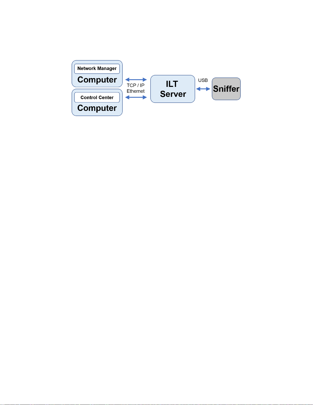
Figure 1- 1. ILT hardware schematic
The following items are recommended for a temporary installation or system testing:
Tripods (useful for positioning anchors in a temporary space)
Gaffer Tape – 1” width (useful for securing anchors and batteries in a temporary place,
without leaving behind an adhesive residue)
Batteries with USB Type B to Micro USB cables (for powering anchors) – Output Voltage
must be 5V, capable of outputting current of at least 1 Amp. We recommend a capacity of
at least 5000 mA-Hours.
USB cable Type A to type B (for connection between the sniffer and the Intel NUC)
Ethernet cable (for connection between computer and Intel NUC)
For a long-term installation, you may require additional materials which should be determined on a
case-by-case basis.
To place the ILT anchors, use the following guidelines:
The minimum space that the ILT system can operate in with stable performance is 5
meters along each dimension (X, Y, Z).
Anchors should be positioned every 30 – 35 meters. The current build will support
anchors placed with a maximum distance between all anchors of 100 meters.
Anchors should bound the perimeter of the 3-D space where the drones will travel.
Anchors should be placed on the highest plane closest to the ceiling and on the floor
(ground plane). Anchors placed in between the ceiling and floor are optional.
Avoid placement of anchors near metallic objects and if possible, leave a clearance of
15cm between the anchor and the wall or ceiling.
The coordinator (first anchor to join the network) and sniffer must be in the direct line of
sight of all anchors.
The coordinate frame follows the right-hand rule. Anchor 1 defines the origin of the ILT
spatial coordinates. The line between Anchor 1 and Anchor 2 defines the X-axis, and the
plane that runs through Anchors 1, 2 and 3 defines the X-Y plane (where Z = 0).
6
© Intel
Page 7

Figure 1- 2. Anchor orientation
The placement of a particular anchor should be chosen to maximize the line of sight
between this anchor and as many other anchors as possible. All anchors must also
maintain line of sight with coordinator and sniffer.
In general, a minimum of 6 anchors is needed to enable the 3-D localization of a drone
within your space, but you may need to install more anchors to improve the accuracy and
redundancy of your network.
When placing anchors on the ceiling and floor planes, we recommend choosing the
placement so as to diversify the X and Y coordinates of anchors in the network. (See the
below figure for an anchor placement example).
Figure 1- 3. Optimal placement of anchors
We recommend that the anchors be installed vertically, with the anchors on the ground
antennas pointing up and anchors on the ceiling antennas pointing down.
© Intel
7
Page 8

Table 2-1. Hardware Requirements
Component
Minimum
Recommended
Processor
64-bit Dual-Core
64-bit Quad-Core
Memory
8GB
16GB
Hard Drive
200GB
500GB
Screen
1920x1080
1920x1080 (touch sensitive)
Table 2-2. Software Requirements
Component
Minimum
Recommended
OS
Windows 10 64-bit
Windows 10 64-bit
Framework
Microsoft Visual C++ 2017 Redistributable
2 Software
Note: This chapter describes the IT requirements for the Intel® Shooting Star Mini™ system.
2.1 IT Requirements
In order to use the Intel® Shooting Star Mini™ system, the operator must provide basic IT
equipment, such as a PC with the Windows 10 operating system. An uninterrupted power supply,
which protects the PC from a power surges and outages, is also recommended.
2.2 ILT Configuration
The ILT network is needed in order for Control Center to communicate to the Drones. This
communication link can be established via Ethernet once the ILT network has been configured.
1. Plug in and turn on the Network Server and then attach the sniffer device using a USB cable
that is no more than 5 meters long.
2. Plug in and turn on the Computer and connect it to the Intel NUC using an Ethernet cable that
is no more than 100 meters long.
3. Open the ILT Network Manager. The first time you open this application, it will prompt you to
add the IP address and serial port for the network. After that, the application will default to
the saved network settings and automatically detect and map the anchors that are powered
on in the room. This configuration can be changed by clicking on “System Config” in the Menu.
After a few minutes, the network will automatically detect and display the location of all
anchors in the GUI tab.
4. You will need to examine the monitoring page and click on the red anchor and link cards, to
view recommendations for optimizing the network set-up.
8
© Intel
Page 9

5. In order to ensure that the network is calibrated properly, we suggest that you perform a
static and a dynamic test using the anchor and tag tracking tool in the GUI. A static test can
be used to check the network quality over time. You will turn on the tracking tool and allow
the system to track the anchor locations for at least 15 minutes.
6. After the network has converged to produce a stable static test, you may proceed to the
dynamic test. The tracking tool allows the user to highlight a particular anchor or tag in a
different color; you can use this feature to perform a dynamic test of the network. Power on a
tag. The system will automatically detect the tag and show it in the GUI. Next, turn on the
tracking feature and select the tag that is powered on. The GUI will automatically highlight this
tag in a different color. Now carry the tag around the room. You should see a highlighted path
on the screen that corresponds with your trajectory.
7. After your system has successfully passed the static and dynamic tests, you are ready to
begin using your network.
8. Set IP address of wired Ethernet connection via Control Panel/Network and
Internet/Network Connections and disable Firewalls.
© Intel
9
Page 10

Main View
Top Bar
Bottom Bar
Side View
Settings file
2.3 Control Center
After installing the Intel® Shooting Star Mini™ Control Center software, the operator will be able to
access and control the Drones. The following content will provide information on a few key features
and commands, but does not cover all features of the Control Center.
2.3.1 User Interface
The following picture shows the user interface (UI) of the Control Center. There are four main groups.
Figure 2-1. Control Center UI Layout
2.3.1.1 Top Bar
The Top Bar provides access to key commands, such as Land, Emergency Land and Power Off. It also
displays the total number of Drones available, and provides a button on the right-hand side to upload
.JSON settings files which can pre-load settings into the Show tab found in the Side View.
2.3.1.2 Bottom Bar
The Bottom Bar tabs can be used to switch between different Main View modes.
2.3.1.3 Main View
The Main View will show data regarding the fleet as specified by the Bottom Bar, such as the status of
each Drone in Detail mode and a general overview of the Drones in Overview mode.
2.3.1.3.1 Detail
In this mode of the Main View, all Drones will be shown in a list. Each Drone is represented by a box,
which expands if it is selected. It will collapse again if it is unselected.
Last Update: The time passed since an update was received from the Drone.
Voltage: The voltage is the battery voltage at the time the last update was received.
10
© Intel
Page 11

Temperature: The current temperature of the Drone at the time the last update was received.
Version Patch: The current firmware version of the Drone.
2.3.1.4 Side View
Within the Side View, the operator will be able to access key commands for the Intel® Shooting Star
Mini™ system.
2.3.1.4.1 Periphery
Currently, the functions featured on this tab are only used for outdoor drone light shows.
2.3.1.4.2 Show
Audio / Load: This will load an audio file to be used during the animation.
Audio / Start: This function allows for manual start of audio playback.
Animation / Load: This will load an animation file to be used for a flight.
Animation / Upload: This will upload the animation file to be used for a flight via network to the
Drones.
Parameters / Transmit Parameters: This will transmit the previously loaded parameters to the
Drones via ILT.
Start and Landing / Compute: This will initiate the optimisation algorithm and allocate the specific
Drones to be used for the flight.
Start and Landing / Transmit Optimisation: This will transmit the optimisation data to the Drones
via ILT.
Timecode / Start: Starts timecode
Show Controls / Transmit Times: This transmits timecode synchronization data to Drones via ILT.
Show Controls / Arm Timed Show: Arms the Drones for launch.
2.3.1.4.3 Manual
Flight Commands / Launch and Hover Selected: This command will power on the Drone‘s motors
and cause it to take-off vertically to 2m height above ground. The Drone will remain in this position
until a landing command has been sent.
2.3.1.4.4 Settings
Indoor Positioning / Try Reconnect: This command will connect the Drones to the ILT network.
Indoor Positioning / Reset Localization Time: This command will synchronize timing of drones
with Control Center.
Firmware / Load: This will load a firmware to upload to Drones.
Firmware / Upload / Stars: This will upload firmware to Drones.
© Intel
11
Page 12

3 Basic Operations
Note: This chapter provides a basic understanding of the operations of the Intel® Shooting
Star Mini™ system.
3.1 Simple Test Flight
The simplest way to have an Intel® Shooting Star Mini™ Drone flying is to perform a test flight. A test
flight is a flight to a fixed height, straight above its take-off point. All commands are initiated manually
within the Control Center.
1. Under Settings / Indoor Positioning select Try Reconnect to connect to the ILT network.
2. Power on the Drone to be flown using the on-board switch.
3. Verify that the Drone appears in the Control Center Main View (Detail).
4. Select the Drone.
5. In the Side View under Manual / Maintenance / Calibration select the Launch and Hover
Selected command with a sustained click/press.
6. In the Side View under Manual / Maintenance / Calibration select the Launch and Hover
Selected command with a sustained click/press.
7. The Drone‘s motors should turn on and it should take off vertically to a height of 2m above
ground. The Drone will hold its position until a landing command has been sent.
8. In the Top Bar, perform the Land All command. The Drone will now land.
3.2 Basic Animation Flight
In order to perform an automated animation flight, the operator is required to have a complete setup
of the Intel® Shooting Star Mini™ system. This section will not describe in detail how to perform a
light show, but it will describe the basic steps to perform a flight, if the animation file and the
parameters file for the specific location have been provided.
1. Under Settings / Indoor Positioning select Try Reconnect to connect to the ILT network.
2. Power on the fleet of Drones to be flown.
3. Load the provided settings file (.JSON format) located under
C:/ShootingStar/Parameters/.
4. Verify that all Drones have appeared in the Control Center Main View (Detail or Overview).
5. Verify that correct animation and audio files were loaded as specified by settings file.
6. Set start frame of audio playback as needed for animation sync.
7. Upload the animation file to the Drones with the Show / Animation / Upload command.
8. Verify that all Drones have received the animation file and have successfully rebooted after
the upload has completed.
9. Transmit the parameters with the Show / Parameters / Transmit Parameters command.
10. Verify that all Drones have received the parameters.
11. Set Optimisation priority and compute optimization with the Show / Start and Landing /
Optimisation / Compute command.
12. Transmit optimization with the Show / Start and Landing / Live / Transmit Optimisation
command
13. Verify that the required number of Drones have received the optimization (i.e. as many
Drones as are needed for animation).
14. Set start frame of animation under Show / Timecode / Start Time / Frame.
15. Expand Timecode start button by clicking “>” symbol next to Show / Timecode / Local.
© Intel
12
Page 13

16. Start Timecode by clicking Show / Timecode / Local / Start.
17. Sync Drones with CC with the Settings / Indoor Positioning / Server / Reset
Localization Time command.
18. Transmit times to Drones with the Show / Show Controls / Synchronisation / Transmit
Times command.
19. Verify that necessary number of Drones have received times.
20. Arm Drones for flight with the Show / Show Controls / Safety Controls / Arm Timed
Show command.
21. Verify that necessary number of Drones have been armed.
22. Supervise the launch and verify that all Drones have launched successfully.
23. Supervise the animation flight and watch for any Warning/Error flags during show.
24. After the Drones have returned to the Launchpad area, use the Highlight All command to
confirm that all Drones have now landed.
25. Disarm the Drones using the Show / Show Controls / Safety Controls / Disarm Timed
Show command.
26. Stop timecode using the Show / Timecode / Local / Stop command.
27. Return Drones to Launchpads.
28. Disconnect power to Launchpads.
29. Power off Drones using the Power Off All command.
© Intel
13
Page 14

4 Regulatory and Safety Information
This device complies with part 15 of the FCC rules. Operation is subject to the following two
conditions:
(1) This device may not cause harmful interference, and
(2) this device must accept any interference received, including interference that may cause
undesired operation.
This equipment may only be operated indoors. Operation outdoors is in violation of 47 U.S.C.
301 and could subject the operator to serious legal penalties.
Warnings
Read manual before use!
Do not disassemble drone, anchor or launch pad.
The anchors must be powered by battery pack for safety reasons (power outages)!
Avoid to handle drones when powered:
o When illuminated the drone is active and should not be handled manually without
wearing safety gloves (PSE)!
Li-Ion Battery – risk of fire! Do not open, crush or heat!
o The battery may explode or cause burns, if disassembled, crushed or exposed to fire or
high temperatures. Do not short or install with incorrect polarity!
o The battery should not be opened, destroyed or incinerate, since they may leak or
rupture and release to the environment the ingredients that they contain in the
hermetically sealed container!
o Do not short circuit battery terminals, or over charge the battery, forced over-discharge,
throw to fire!
o Do not crush or puncture the battery, or immerse in liquids!
o Precautions to be taken in handling and storing the battery: Avoid mechanical or
electrical abuse. Storage preferably in cool, dry and ventilated area, which is subject to
little temperature change. Storage at high temperatures should be avoided. Do not
place the battery near heating equipment, nor expose to direct sunlight for long
periods!
© Intel
14
Page 15

FCC Part 15.21 Warning:
"CAUTION: Changes or modifications not expressly approved by Intel could void the user's
authority to operate the equipment."
FCC Part 15.105(b) Warning & Interference Statement:
This equipment has been tested and found to comply with the limits for a Class B digital device,
pursuant to part 15 of the FCC Rules. These limits are designed to provide reasonable
protection against harmful interference in a residential installation. This equipment generates,
uses and can radiate radio frequency energy and, if not installed and used in accordance with
the instructions, may cause harmful interference to radio communications. However, there is
no guarantee that interference will not occur in a particular installation. If this equipment does
cause harmful interference to radio or television reception, which can be determined by
turning the equipment off and on, the user is encouraged to try to correct the interference by
one or more of the following measures:
Reorient or relocate the receiving antenna.
Increase the separation between the equipment and receiver.
Connect the equipment into an outlet on a circuit different from that to which the
receiver is connected.
Consult the dealer or an experienced radio/TV technician for help.
Instructions
Unpacking, Packing, Transport, Storage
Safety of work training and safety briefing is mandatory
Personnel is required to wear safety gloves (PSE) when handling items
Continuous monitoring and event reporting is to be implemented and conducted
Safety Audits shall be conducted
Preparation, Post-Operation
Crew Training is required
Safety of work training is mandatory
First aid kit (automobile grade) and trained first aid personnel to be at site
Enforcement of safety area with restricted access (crew only; no exposure to third
party)
Drones shall be handled by trained and qualified personnel only
o Drones are not operated on ground when out off launch pad, nor launched or
captured by hand
Ensured carefree passing through adjacent items by established minimum distance
© Intel
15
Page 16

o Cable routes shall be guarded by use of railings, industrial safety gates, floor hole
covers or toe-boards
o Minimal passing between items shall take place once initial setup is complete.
Launch pads can be directly next to each other.
Continuous monitoring and event reporting shall be implemented and conducted
A Battery Maintenance Plan shall be implemented and adhered to
Replace all mechanical parts that have been damaged or have been subject to known
over load
Safety Audits shall be conducted
Operation
Operational safety and safety of work training is mandatory
o Crew shall be trained to perform typical tasks and to operate safely
o Safety Briefing and safety training is mandatory
o If interacting with performers a choreography shall be developed and trained,
and rehearsals shall be conducted
Regular inspection before commission according to checklist shall be conducted and
documented
Geo fence to terminate flight within pre-defined safety area must be defined and
implemented.
Limit operational altitude to 50m AGL; implement 1:1 rule to audience when flying more
than 50m AGL
Operations shall be suspended when adequate level of safety cannot be maintained
If required due to an inability to control environmental conditions, enforcement of
safety area with restricted access (here: crew only; no exposure to third party) shall be
conducted
Avoid passing between items on the ground
© Intel
16
Page 17

5 Drone Battery Handling –
Precautions and Guidelines
Charging temperature
The drone battery shall be charged within 10℃~45℃ range in the Product Specification.
Discharging temperature
Drone battery discharge temperature is -20℃~60℃.
5℃~45℃ environment is suggested when discharging with high current, small current discharge is
suggested under 5℃ and above 45℃.
Discharge under too low or too high temperatures could lead to drone battery failure or other
conditions.
Storage
When voltage is 3.7V~3.9V, the drone battery could be stored for long term in the environment
humidity ≤75%RH temperature -20~35℃. Activate the drone battery once every three months, so as to
keep voltage within 3.7V~3.9V.
When voltage is over 3.9V, the drone battery should be stored in the environment humidity ≤75%RH,
temperature -20~35℃. Storage time should be less than 7 days.
© Intel
17
 Loading...